SENDOT FluoMini Pro User manual

User manual
System information
FluoMini Pro type: 400
Firmware: version 191010
Software: version 2.17
Baudrate: 19200
www.sendot.nl
FluoMini Pro Optical pH Sensor

2
Contents
1. General.......................................................................................................................... 4
1.1. Product....................................................................................................................... 4
1.1.1. Scope of delivery .................................................................................................... 4
1.1.2. Technical specifications .......................................................................................... 4
1.2. Important user instructions ......................................................................................... 5
1.3. Warranty..................................................................................................................... 6
1.4. Transport, storage and disposal ................................................................................. 6
2. Installation...................................................................................................................... 7
2.1. Unpacking and setup.................................................................................................. 7
2.2. Type probe ................................................................................................................. 7
2.3. Connections ............................................................................................................... 7
2.3.1. Handheld sensor..................................................................................................... 7
2.3.2. Digital sensor .......................................................................................................... 7
2.3.3. Analog sensor......................................................................................................... 8
2.4. Display and buttons.................................................................................................... 9
3. Measuring with the FluoMini Pro Optical pH Sensor .................................................... 10
3.1. Measurement principle ............................................................................................. 10
3.2. Ending the standby mode......................................................................................... 10
3.2.1. Handheld sensor................................................................................................... 10
3.2.2. Digital sensor ........................................................................................................ 10
3.2.3. Analog sensor....................................................................................................... 10
3.3. Measurements.......................................................................................................... 11
3.3.1. Single measurement ............................................................................................. 11
3.3.2. Continuous measurements ................................................................................... 11
3.4. Logger and transmitter function ................................................................................ 11
4. Settings........................................................................................................................ 12
4.1. Main menu ............................................................................................................... 12
4.2. General settings ....................................................................................................... 12
4.2.1. Date/Time ............................................................................................................. 12
4.2.2. Power management.............................................................................................. 13
4.2.3. Save data ............................................................................................................. 13
4.2.4. Decimal separator................................................................................................. 13
4.3. Logger settings (handheld/digital)............................................................................. 13
4.3.1. Logger On/Off ....................................................................................................... 14
4.3.2. Interval time .......................................................................................................... 14
4.3.3. Memory................................................................................................................. 15

3
4.4. Transmitter settings (analog) .................................................................................... 15
4.4.1. Transmitter On/Off ................................................................................................ 16
4.4.2. Interval time .......................................................................................................... 16
4.4.3. A-out Test ............................................................................................................. 16
4.4.4. Memory................................................................................................................. 17
4.5. Sensor settings......................................................................................................... 17
4.5.1. Calibrate ............................................................................................................... 17
4.5.2. Enter Cal. data...................................................................................................... 18
4.5.3. Measurement setting ............................................................................................ 19
4.6. System info .............................................................................................................. 19
5. Troubleshooting ........................................................................................................... 20

4
1. General
1.1. Product
Product FluoMini Pro Optical pH Sensor
Version 1
Software 2.17
Firmware 191010
1.1.1. Scope of delivery
•FluoMini Pro Optical pH Sensor (handheld, analog or digital)
•Fiber with probe equipped with sensitive coating
•USB cable
•Analog cable (for analog sensor only)
•Digital cable (for digital sensor only)
•Pre-drill
•Probe support
•USB stick with user manual and FluoMini Software Suite
•Quick Guide
•Installation sheet (for digital and analog sensors only)
1.1.2. Technical specifications
Specifications Values
pH range 3.0 – 8.5
Temperature range + 5 to + 45 °C
Accuracy pH 3.5 – 4.0 ± 0.2 pH
Accuracy pH 4.0 – 7.0 ± 0.1 pH
Accuracy pH 7.0 – 8.5 ± 0.2 pH
Resolution pH 0.01 pH

5
Response Time pH (T90) ≤30 sec (depending on flow rate)
Drift / Stability pH 3.5 – 4.0 / 7.5 – 8.5 ≤0.2 pH per month (measurement frequency 1/min)
(depends on measurement frequency)
Drift / Stability pH 4.0 – 7.0 ≤0.1 pH per month (measurement frequency 1/min)
(depends on measurement frequency)
Sample time ≤2 sec (freq. > 1.25 Hz)
Calibration 2 point (pH 4.00 and 7.00)
Coating lifetime 400.000 measurements
Connectivity Handheld: USB serial interface
Digital: USB serial interface
digital output / TTL serial port
Analog: USB serial interface
4 – 20 mA output (4 wires)
12 – 24 V AC/DC
Output signal USB serial interface port
Dimensions (l x w x h in mm) 169 x 62 x 25
Weight (g) 235
Housing material Aluminium, with ABS covers
Electrical connections Handheld: 1 x M5 4 pole male
Digital: 2 x M5 4 pole male
Analog: 1 x M5 4 pole male
1 x M5 4 pole female
Probe material Stainless steel (6mm OD, l = 100) with optical fiber
Protection level IP53
Power supply Handheld/digital: USB port (5V, < 200 mA)
Analog:12-24 V
Battery lifetime (handheld/digital) 48 h at 5 sec interval
2 weeks at 60 sec interval
1.2. Important user instructions
This sensor is suitable to measure in aqueous solutions. The sensor is not suitable to measure
in strongly oxidizing media, so as strong acidic (pH < 2) and strong basic (pH > 10) solutions.
The pH coating should be treated with care, because it can be damaged mechanically with
CAUTION! Direct contact between the pH sensitive coating and the medium to be measured is
important for an adequate measurement. Please, use the included pre-drill & probe support for
measurements in substrates and other solids to protect the coating from any damage.

6
sharp, edged objects. Damaged coatings can lead to erroneous measurement results. If the
sensor is used in solid substrates, use the probe support and pre-drill to make a hole after
which the sensor can be pushed in the substrate cautiously. Some strong (fluorescing) dyes
might disturb the measurement; we are constantly improving our sensors. Please keep
following our website (www.sendot.nl) to check for any new developments.
1.3. Warranty
This product has a warranty of two years on the mechanics and electronics (excl. battery).
The sensitive coating can be used for a period depending on the measurement frequency and
environment where the sensor has to operate in, like temperature, pressure and average
oxygen partial pressure.
1.4. Transport, storage and disposal
This product is subject to the “GENERAL RESEARCH, ADVICE, SALES, DELIVERY AND
PAYMENT CONDITIONS OF SENDOT RESEARCH BV (deposited with no. 62488295 bij KvK
Haaglanden)”. It can be downloaded from www.sendot.nl.
7
2. Installation
2.1. Unpacking and setup
The sensor will be delivered with the probe attached. It has been calibrated, ready to be used.
Before first use, the sensor might need to be charged using the included USB cable. The
display is protected with a plastic film that can be removed.
For the installation of a digital or analog sensor, please read the included installation sheet.
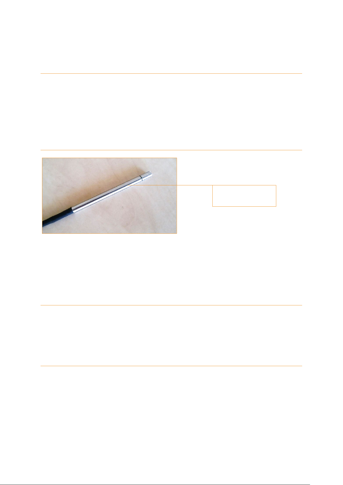
2.2. Type probe
The FluoMini Pro Optical pH Sensor is provided with a stainless steel probe with an outer
diameter of 6 mm.
2.3. Connections
2.3.1. Handheld sensor
The sensor can be connected to a Windows or Android system by means of a USB cable.
Charging is possible via the USB port. A battery is included, so the sensor does not necessarily
need to be attached to a power source for use.
2.3.2. Digital sensor
The sensor can be connected to a Windows or Android system by means of a USB cable.
Charging is possible via the USB port. A battery is included, so the sensor does not necessarily
need to be attached to a power source for use. Additionally, a digital input/output can be used
to attach the sensor to an external control device, e.g. a wireless transmitter.
Stainless steel probe

8
2.3.3. Analog sensor
The sensor can be connected to a Windows or Android system by means of a USB cable. A
battery is not included, so the sensor has to be attached to a power source via the USB port
for use. Additionally, an analog output can be used to attach the sensor to an external control
device (e.g. a climate computer). The sensor will also be powered through this port.

9
2.4. Display and buttons
In the picture below the basic sensor screen is shown, as well as the buttons with their names
as being used in this manual.
1 Battery
2 Measurement indicator
3 Measured pH
4 Measurement unit
5
Menu/Exit button
With this button the main menu can be entered and every menu can be quit.
The feature of this button is always visible on the display (bottom left).
6
Measure/Enter button
This button is used to end the standby mode.
This and additional features of this button are always visible on the display (bottom right).
This button has a number of features, but for simplicity, it is named Measure/Enter button
throughout this manual.
7 Down button
8 Up button
2
6
8
5
7
4
1
3

10
3. Measuring with the FluoMini Pro Optical pH Sensor
3.1. Measurement principle
The measurement with the FluoMini Pro Optical pH Sensor is based on a pH sensitive active
component integrated in a hydrophilic polymer coating. The integrated pH sensitive
component contains an indicator molecule having different optical behaviour in protonated and
deprotonated state. The ratio between these states is pH dependent. The sensor does not
use a reference electrode, why it does not suffer from the inherent problems connected to
reference electrodes.
3.2. Ending the standby mode
3.2.1. Handheld sensor
To save energy the sensor display automatically turns off after 30 seconds. During battery
operation, the sensor will automatically go into standby mode after 1 min. The sensor will wake
up again when the Measure/Enter button is pressed. When the sensor is attached to a
computer or external power source, it will not turn into standby mode, only the display will turn
off.
3.2.2. Digital sensor
When the sensor is connected to an external control device (e.g. a computer) through the USB
port, it will wake up when the Measure/Enter button is pressed. From that moment on, it will
respond like a regular handheld sensor. When the sensor is connected through the serial
digital port it will operate in a special mode. For more information about running the sensor
through the digital port please contact Sendot Research via phone (+31 (0)30-636-8477) or
e-mail ([email protected]).
3.2.3. Analog sensor
This sensor has no battery, why it always has to be attached to a power source to operate.
The sensor display automatically turns off after 30 seconds. When the sensor is connected to
an external control device (e.g. a computer) through the USB port, it will operate as a regular
handheld sensor. When it is connected via the analog port it will also never turn into standby
mode. As soon as the sensor is coupled to an external control device it will start measuring
with the interval specified in the sensor and output the analog value through the port.

11
3.3. Measurements
Apply the probe to the medium to be measured. For measurements in substrates, always use
the probe support and pre-drill to avoid damages on the coating. Therefore, first apply the
probe support at the desired position, make a hole using the pre-drill and carefully stick in the
probe until the bottom of the hole. In liquid media, air bubbles caught up on the coating can
result in false measurements, why they have to be avoided.
3.3.1. Single measurement
1. Press the Measure/Enter button to activate the sensor.
2. Press the Measure/Enter button again to start a single measurement.
3.3.2. Continuous measurements
In continuous measurement mode the sensor will perform a measurement every 2 seconds.
To activate this mode:
1. Press the Measure/Enter button to activate the sensor.
2. Press the Measure/Enter button for 2 seconds to start continuous measurements.
3. Press the Measure/Enter button for 2 seconds to stop continuous measurements.
3.4. Logger and transmitter function
With this sensor it is possible to measure continuously. In case of a handheld and digital
sensor, the data is stored on the internal memory (for further information on this function see
chapter 4.3). In case of an analog sensor, the data is send to an external device, e.g. a
computer (for further information on this function see chapter 4.4).
Tip: The sensor will store single measurements not automatically. This can be changed. For further
information see chapter 4.2.3.
Tip: The sensor will store measurements not automatically. This can be changed. For further
information see chapter 4.2.3 and 4.3.
12
4. Settings
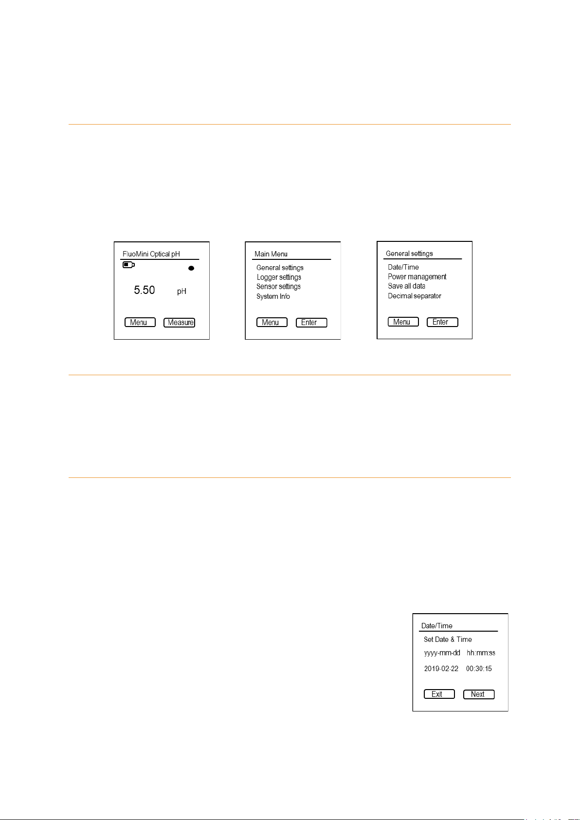
4.1. Main menu
The main menu can be entered by pressing the Menu/Exit button. The screen with the different
setting options will be opened.
The main menu consist of four submenus: <General settings>, <Logger settings>, <Sensor
settings>, and <System info>. To navigate towards any menu use the Up and Down buttons
and enter a submenu with the Measure/Enter button.
4.2. General settings
The menu <General settings> contains submenus to set date and time, control power
management, save data and change the decimal separator. Use the Up and Down buttons to
navigate to the desired submenu. To enter a submenu press the Measure/Enter button.
4.2.1. Date/Time
In this menu, date and time can be set manually. Alternatively, date and time can be
synchronized with the current date and time on the computer using the FluoMini Sensor
Software Suite (for further information see manual for FluoMini Sensor Software Suite).
Default, date and time are set to 0:00:00, 01/01/1999 and have to be set after a restart due to
an empty battery or a hard reset (pressing Menu/Exit button and Measure/Enter button parallel
for 30 sec).
1. Open the menu <General settings>.
2. Open the menu <Date/Time>.
3. Use the Up and Down buttons to set date and time.
4. Use the Measure/Enter button (Next) to navigate to the next
position in date and time.
5. Confirm settings and close menu with the Measure/Enter button.
13
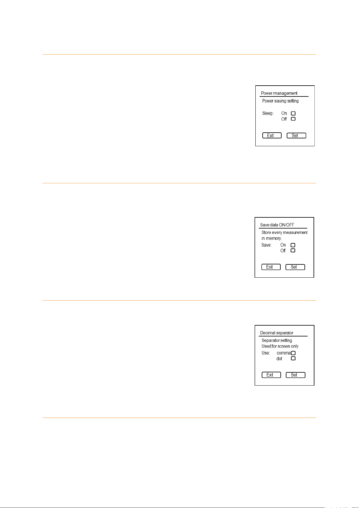
4.2.2. Power management
In this menu, the standby mode can be turned on and off. Default, this function is turned on,
so the sensor will turn into standby mode after 30 sec.
1. Open the menu <General settings>.
2. Open the menu <Power management>.
3. Use the Up and Down buttons to choose the desired setting.
4. Confirm setting and close menu with the Measure/Enter button
(Set).
4.2.3. Save data
In this menu, automatic storage of every measurement can be turned on and off. Default, this
function is turned off.
1. Open the menu <General settings>.
2. Open the menu <Save all data>.
3. Use the Up and Down buttons to choose the desired setting.
4. Close menu with the Measure/Enter button (Set).
4.2.4. Decimal separator
In this menu, the decimal separator for values shown on the screen can be changed.
1. Open the menu <General settings>.
2. Open the menu <Decimal separator>.
3. Use the Up and Down buttons to choose the desired setting.
4. Confirm setting and close menu with the Measure/Enter button
(Set).
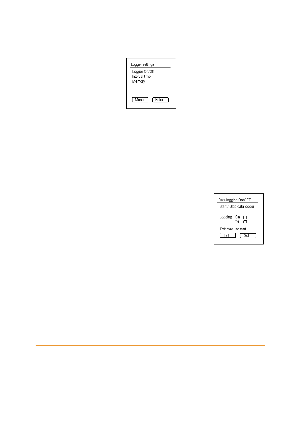
4.3. Logger settings (handheld/digital)
With the logger function continuous measurements are performed and stored internally. Within
the menu <Logger settings> the logger function can be turned on and off, the interval time of
14
the measurements can be set or the stored data erased. Use the Up and Down buttons to
navigate to the desired submenu. To enter a submenu press the Measure/Enter button.
Remark: If the sensor is in logging mode, it is not possible to communicate with the sensor
through an external device, e.g. a computer. Logging has to be stopped first to communicate
with the sensor. Nevertheless, by pressing the Measure/Enter button the last measured value
will be visible on the display.
4.3.1. Logger On/Off
In this menu, the logger function can be turn on and off.
1. Open the menu <Logger settings>.
2. Open the menu <Logger On/Off>.
3. Use the Up and Down buttons to choose the desired setting.
4. Confirm the setting with the Measure/Enter button
(Set).
5. Exit menu with the Menu/Exit button. Logging will start automatically.
If date and time have not been set in advance, the sensor will show an error (Date & Time not
set.). In this case, the logger function can still be started, if wanted. To start the logger function
press the Measure/Enter button (Ignore) or wait for 5 sec. The start date and time will be set
to 00:00, 01/01/1999. Another option is to cancel the logger function by pressing the Menu/Exit
button (Cancel). Now, date and time can be set before the logging function is started again
(see chapter 4.2.1).
4.3.2. Interval time
In this menu, the time interval between the measurements during logging can be changed.
For the most applications, an interval time of 5 min or higher is sufficient. The interval time
should be set before the first use of the sensor.

15
1. Open the menu <Logger settings>.
2. Open the menu <Interval time>.
3. Use the Up and Down buttons to change the value.
4. Use the Measure/Enter button (Next) to navigate to the next
position in time (hh:mm:ss).
5. Confirm the setting and close menu with the Measure/Enter button.
4.3.3. Memory
In this menu, the storage volume in total as well as used by stored data can be read. The
stored data can be deleted.
1. Open the menu <Logger settings>.
2. Open the menu <Memory>.
3. Use the Up and Down buttons to choose the desired setting.
4. Confirm the setting and close menu with the Measure/Enter
button (Set).
It is advisable to use the FluoMini Sensor Software Suite to store the data on a computer
before the data is deleted from the sensors memory.
4.4. Transmitter settings (analog)
With the transmitter function continuous measurements are performed and send to an external
device, e.g. computer. Within the menu <Transmitter settings> the transmitter function can be
turned on and off, the interval time of the measurements can be set, stored data erased and
the analog output being tested. Use the Up and Down buttons to navigate to the desired
submenu. To enter a submenu press the Measure/Enter button.
16
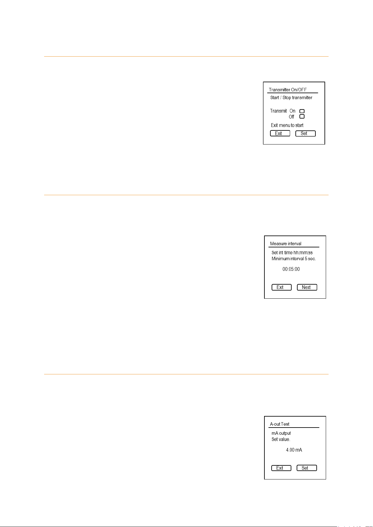
4.4.1. Transmitter On/Off
In this menu, the transmitter function can be turn on and off.
1. Open the menu <Transmitter settings>.
2. Open the menu <Transmitter On/Off>.
3. Use the Up and Down buttons to choose the desired setting.
4. Confirm the setting with the Measure/Enter button
(Set).
5. Exit menu with the Menu/Exit button. Transmitting will start automatically.
4.4.2. Interval time
In this menu, the time interval between the measurements transmitted can be changed. For
the most applications, an interval time of 5 min or higher is sufficient. The interval time should
be set before the first use of the sensor.
1. Open the menu <Transmitter settings>.
2. Open the menu <Interval settings>.
3. Open the menu <Interval time>.
4. Use the Up and Down buttons to change value.
5. Use the Measure/Enter button (Next) to navigate to the next position in time
(hh:mm:ss).
6. Confirm the setting and close menu with the Measure/Enter button.
4.4.3. A-out Test
This function only applicable for analog sensors and is to test the analog output signal send
to an external device, e.g. computer.
1. Open the menu <Transmitter settings>.
2. Open the menu <A-out Test>.
3. Use the Up and Down buttons to set a value.

17
4. Confirm the value with the Measure/Enter button (Set). A signal will be send to the
external device, which is translating it into pH.
5. Compare this value with the pH on the external device. Here, 4 – 20 mA are translated
to pH 2 – 12. Therefore, a change of 1 mA relates to a change of 0.6 pH units.
4.4.4. Memory
In this menu, the storage volume in total as well as used by stored data can be read. The
stored data can be deleted as followed:
1. Open the menu <Transmitter settings>.
2. Open the menu <Memory>.
3. Use the Up and Down buttons to choose the desired setting.
4. Confirm setting and close menu with the Measure/Enter button
(Set).
Remark: It is advisable to use the FluoMini Sensor Software Suite to store the data on a
computer before the data is deleted from the sensors memory.
4.5. Sensor settings
Within this menu, the sensor can be calibrated as well as an offset and slope added to the
measured pH value.
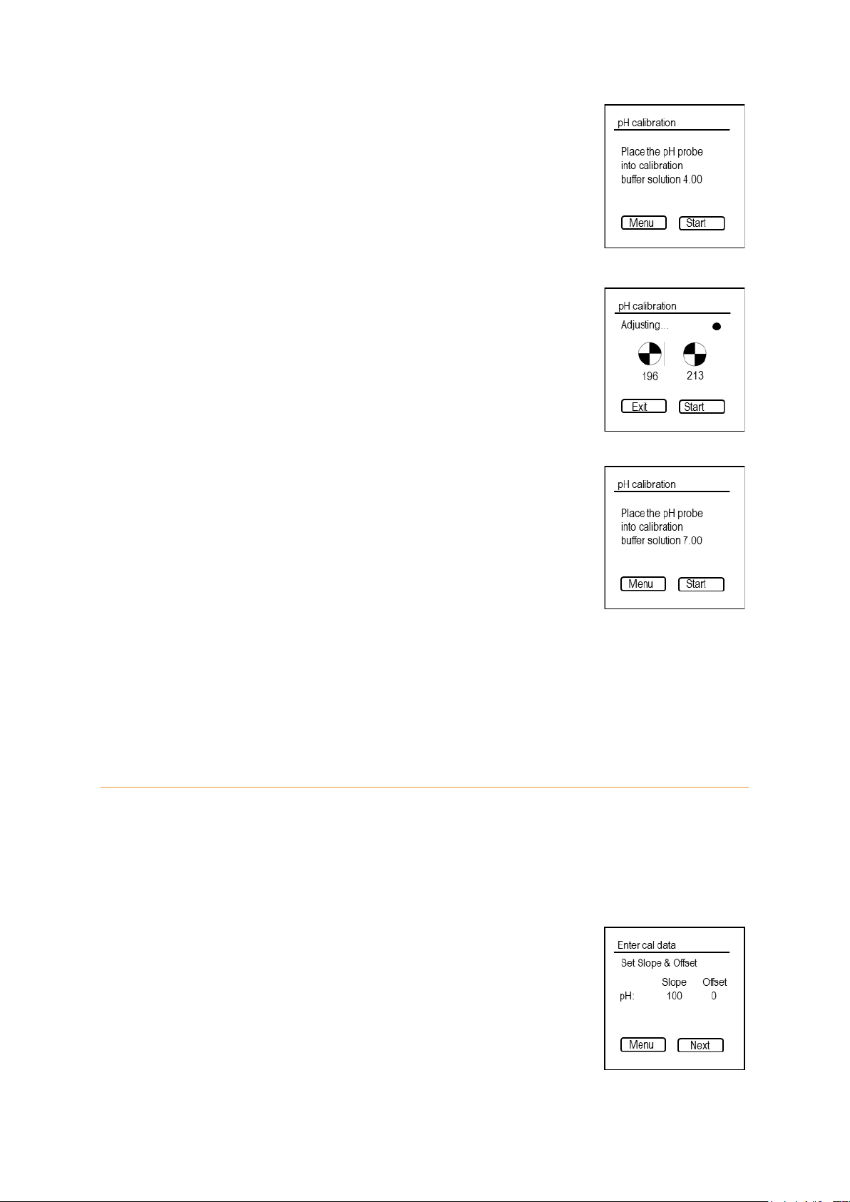
4.5.1. Calibrate
Whenever the fiber with the probe is exchanged or reattached the sensor has to be
recalibrated. In this menu, the sensor can be calibrated automatically. Therefore, a pH 4 and
pH 7 buffer solution are necessary.
18
1. Open the menu <Sensor settings>.
2. Open the menu <Calibrate>
3. Place probe into pH 4 buffer and wait for 1 min to stabilize.
Stirring is advisable for fast stabilisation.
4. Press the Measure/Enter button (Start) and follow the
instructions on the display. The sensor will adjust itself to its
optimal settings. It uses a maximum of three attempts to adjust
itself. If this fails, the probe should be checked for damages
and/or the fiber reattached. Subsequently, the calibration can
be restarted.
5. Keep the probe in pH 4 buffer until you are instructed to place it
into pH 7 buffer.
6. Rinse the probe carefully with demineralized water and place it
into pH 7 buffer. Wait for 1 min to stabilize. Stirring is advisable
for fast stabilisation.
7. Press the Measure/Enter button (Start) and wait until the sensor
finishes the calibration.
8. The display will show the calculated calibration values and finalize the calibration with
the comment “Finished successfully”.
9. Press the Menu/Exit button to close the menu.
4.5.2. Enter Cal. data
In this menu, you can add an offset and slope to the measured pH value.
Remark: This function can be used to have a fast correction without the use of buffer solution.
Nevertheless, it is advisable to recalibrate the sensor (see chapter 4.5.1) or replace the fiber
with the probe, when an inacceptable deviation is observed.
1. Open the menu <Sensor settings>.
2. Open the menu <Enter Cal. data>.
3. Use the Up and Down buttons to adjust slope and offset.
4. Use the Measure/Enter button (Next) to navigate to the next
position.

19
5. Confirm settings and close the menu with the Measure/Enter button.
4.5.3. Measurement setting
For the FluoMini Pro Optical pH Sensor this function is not applicable.
4.6. System info
The menu System info contains information about the FluoMini type,
the installed firmware, the battery voltage and the baud rate necessary
to communicate with the sensor. Additionally, the sensor can be named
using the FluoMini Software Suite (for further info see manual for
FluoMini Software Suite). In this menu, the given name is visible.

20
5. Troubleshooting
The display stays black and the sensor is not reacting anymore.
1. Recharge the sensor using the included USB cable. The battery might be empty.
2. If the sensor is still not responding, reset the sensor by pressing the Up and Down
button at the same time for 2 sec.
3. If the sensor still not reacts, the sensor can be reset to factory settings by pressing the
Up and Down button at the same time for 30 sec.
4. If there is still no response, please contact Sendot Research via phone (+31 (0)30-
The following errors can be visible on the display:
Low signal
1. Check if the fiber is properly attached to the sensor and the coating is still intact.
2. If this message is still shown, the lifetime of the coating might have been reached. In
this case the probe needs to be exchanged. Therefore, please contact Sendot
Error opening logfile
1. Check if the sensor is properly attached to the computer. Reattach the sensor and
press refresh in the menu Sensors in the FluoMini Software Suite.
2. If date & time of the logging strongly changes, reading the logfile might not be possible.
This can happen, if the time has been changed between two log sessions or if the
sensor logged once without a set time & date, followed by logging with set time & date.
It is advisable to set time & date before the first log. If the time changes (e.g. different
time zone), the memory should be emptied in between.
No SD card
1. The communication between the sensor and the internal memory is interrupted. Please
Red battery icon
This icon is showing that the battery is empty. In this case the sensor needs to be
recharged with the included USB cable.
Other manuals for FluoMini Pro
2
Table of contents
Popular Accessories manuals by other brands

Furzone
Furzone 40800 manual

TQ Environmental
TQ Environmental GD133 operating manual

Fire-Lite Alarms
Fire-Lite Alarms CP350 Installation and maintenance instructions

Bodensteckdosen Systemtechnik
Bodensteckdosen Systemtechnik 76 A-Series instruction manual

Vmarker
Vmarker IR-pen Touch manual

Minoston
Minoston Z-Wave Plus MSE30Z manual


LEGRAND
LEGRAND Wattstopper FSP-301 installation instructions

Vaughan
Vaughan 050013 instruction manual

Wavetronix
Wavetronix Click 510 quick start guide

Balluff
Balluff BVS ID-M1280-F1 Series user guide

TP active fun
TP active fun TP208 Instructions for assembly, maintenance and safe use

Lightolier
Lightolier Lytecaster 1095 specification