Seneca K-SUPPLY User manual

ENGLISH - 1/8MI000951-E
K-SUPPLY
K-BUS power supply for K-Series modules
General Description
The K-SUPPLY module permits the delivery of power supply to numerous K-Series
modules through K-BUS connection by creating interface between an external power
supply system and the user module distribution bus. The impossibility of tapping
current from the bus to the input terminals permits the connection of numerous K-
SUPPLY modules in parallel on the same bus together with the protection provided
against polarity inversion permits the module to offer valid protection against
erroneous connections.
Main features:
two independent inputs that permit the use of one power supply system; redundant
power supply that guarantees the presence of power supply even whenever the
source of either input undergoes power failure;
indication of the presence of each channel: the LED switches on only when there is
sufficient voltage for the operation of the K-Series modules connected;
a LED that signals input inverted polarity or alternating current;
built-in over-voltage (surge) protection;
differential mode filter.
Technical features
Number:
Type:
Voltage:
Current carrying capacity:
Protection:
2, with shared negative terminal.
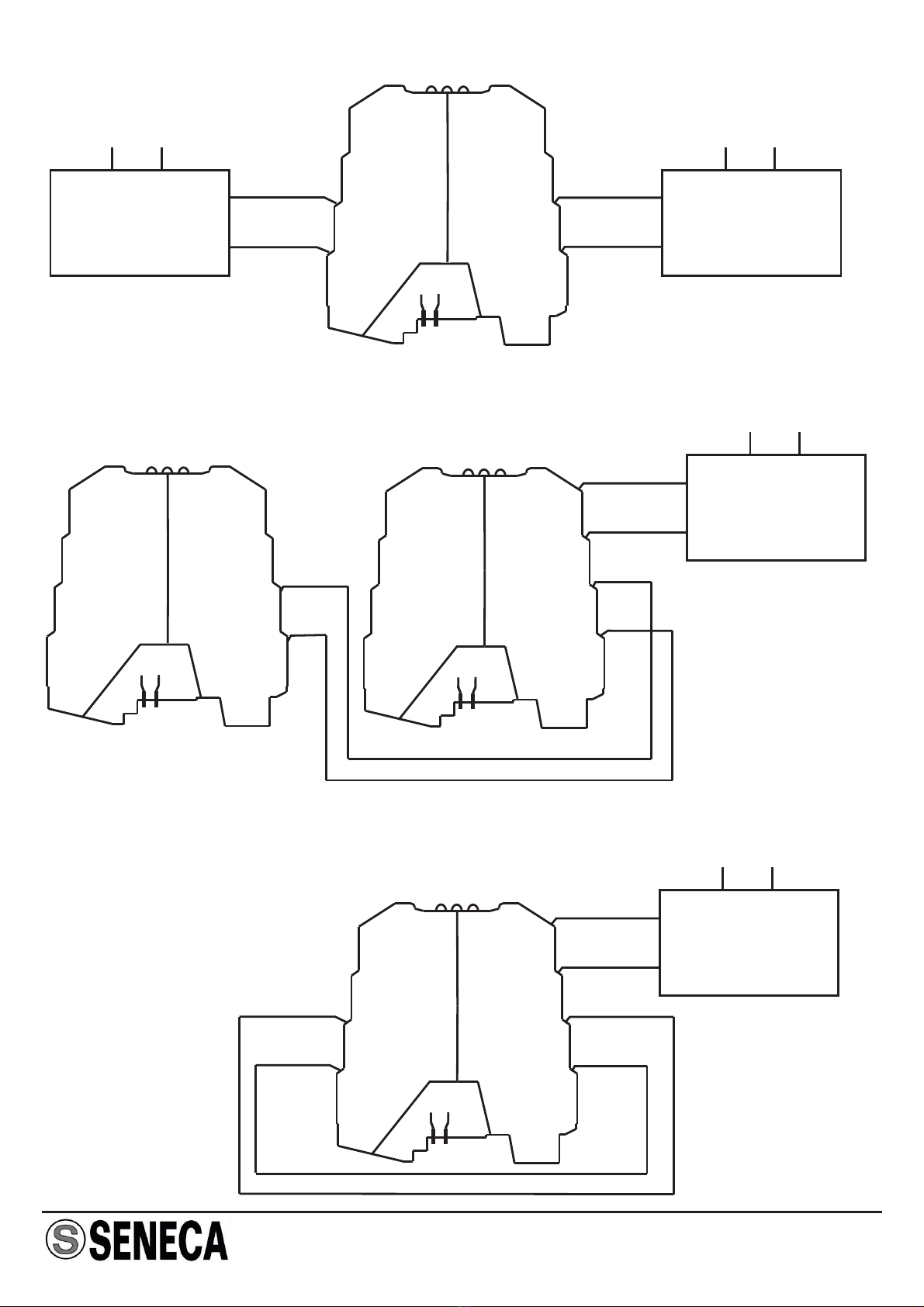
Pass-through: each input can be accessed by two
pairs of terminals, in this way permitting the same
power supply source to be used for more than one
K-Supply module (see the section entitled Example
of Connection to more than one bus).
19,2..30 Vdc
Maximum current per terminal: 4 A
Each positive input must be provided with protection
by an external fuse (see the section entitled Fuse
Sizing Selection).
The device has no limit on maximum current.
Input characteristics
EN

MI000951-E ENGLISH - 2/8
300 mV
Input voltage minus internal voltage drooping value.
One single input: maximum 1.6 A
Inputs 1 and 2 connected in parallel: maximum 2A.
Maximum voltage drop:
Voltage :
Current carrying capacity:
General technical characteristics
Output characteristics
Protection:
Environmental conditions:
Storage temperature:
Connections:
Wire section:
Wire stripping:
Box :
Dimensions and weight :
Reference standards :
IP20
Temperature: -20 … +65°C
Humidity: 10 … 90% non-condensing
Altitude: up to 2000 m. a. s. l.
-40..+85°C
Cable clamp terminals
0,2..2,5 mm2
8 mm
PBT, black
6,2 x 93,1 x 102,5 mm, 46 g.
EN61000-6-4/2002
(electromagnetic emission, industrial environment)
EN61000-6-2/2002
(electromagnetic immunity, industrial environment)
EN61010 (electrical safety)
Other electrical characteristics
Filter:
Power Consumption:
Dissipation:
Differential mode, equal to 4.7 mH & 2 x 470 nF per
input.
Maximum 5 mA per input.
Maximum 600 mW at peak load.

MI000951-E ENGLISH - 3/8
Installation rules
This module has been designed for assembly on a DIN 46277 rail. Assembly in vertical
position is recommended in order to increase the module's ventilation, and no raceways or
other objects that compromise aeration must be positioned in the vicinity.
Do not position the module above equipment that generates heat; we recommend
positioning the module in the lower part of the control panel or container compartment.
K-SUPPLY
K-SUPPLY
1 -Attach the module in the upper part of
the rail.
2 - Press the module downwards.
1 -Apply leverage using a screwdriver (as
shown in the figure).
2 - Rotate the module upwards.
Inserting the module in the rail Removing the module from the rail
Using the K-BUS connector
1 - Compose the K-BUS connectors as required in order to obtain the number of positions
necessary (each K-BUS permits the insertion of no. 2 modules).
2 - Insert the K-BUS connectors in the rail by positioning them on the upper side of the rail
and then rotating them downwards.
sIMPORTANT: Pay particular attention to the po ition of the protrudent terminals of the
K-BUS. The K-bus must be inserted in the guide with the protrudent terminals on the left
(as shown in the figure) otherwise the modules are turned upside downs.
-Never connect the power supply directly to the bus connector on the DIN
rail.
-Never tap power supply from the bus connector either directly or by using
the module's terminals.
!

MI000951-E ENGLISH - 4/8
Numbers of modules Rapid type
_
_
_
100 mA
200 mA
400 mA
1250 mA
1600 mA
2500 mA
Average type Delayed type
2
5
10
20
35
50
70
This section provides indications on the sizing of the fuse to be used for the protection
of the inputs as required by the number of boards that the K-SUPPLY module must
power.
Fuse sizing selection
630 mA
1250 mA
750 mA
1600 mA
_
100 mA
200 mA
400 mA
630 mA
_
_
_
Numbers of modules Rapid type
_
_
_
1250 mA
1500 mA
2 A
Average type Delayed type
2
5
10
20
35
50
70
100
600 mA
1 A
_
300 mA
300 mA
300 mA
500 mA
_
_
_
_
_
2500 mA
_
_
_
1250 mA
1600 mA
The table below provides the sizing recommended per type of fuse for battery-powered
systems (21…30 V) in which surge is not foreseen.
The table below provides the sizing recommended for systems in which surge is
foreseen with 23 to 30V voltage.

MI000951-E ENGLISH - 5/8
8 mm
0,2..2,5 mm2
Electrical connections
Inputs
The module has two inputs (19.2…30V DC) with shared negative terminal.
Input 1
Terminal 1 & Terminal 3: +
Terminal 2 & Terminal 4: -
Input 2
Terminal 5 & Terminal 7: +
Terminal 6 & Terminal 8: -
Terminals 2, 4, 6, and 8 are connected together.
Output
The module provides a K-BUS output equal to the input voltage minus the internal
drooping value. The negative terminal is shared by input terminals 2, 4, 6 and 8. The
module does not permit the tapping of current from the bus to the input terminals.
15
6
7
8
2
3
4
IN2 + IN1 +
+
+
IN2 - IN1 -
IN2 - IN1 -
-
-
+-
+
+
-
-
+
-
-
+
IN2 + I 1N +
OUT
Internal wiring diagram

MI000951-E ENGLISH - 6/8
Example of connection with REDUNDANT POWER SUPPLY
Example of connection to more than one bus
1
1
1
5
5
5
6
6
6
7
7
7
8
88
2
2
2
3
3
3
4
4
4
INPUT 2
INPUT 2
INPUT 2
INPUT 1
INPUT 1
INPUT 1
+
+ +
+
+
+
++
-
- -
-
-
-
--
+
+
+
-
-
-
OUT
OUT
OUT
Power-supply 2 Power-supply 1
Power-supply
Main Main
Main
Bus for supplying K serie devices
Bus 1
Bus 2
15
6
7
8
2
3
4
INPUT 2 INPUT 1
+
+
+
+
-
-
-
-
+-
OUT
Power-supply
Main
Example of connection with inputs connected in parallel: 2 A output

MI000951-E ENGLISH - 7/8
Signalling by LED on the front panel
LED Meaning
Green Led 1 When illuminated, this LED signals the presence of sufficient
voltage for the first input.
The illumination threshold is 19.2 V ± 0.3 V
Green Led 2 When illuminated, this LED signals the presence of sufficient
voltage for a second input.
The illumination threshold is 19.2 V ± 0.3 V.
Red Led When illuminated, this LED signals erroneous input polarity or
alternating current.
The illumination threshold is 2V.

MI000951-E ENGLISH - 8/8
Disposal of Electrical & Electronic Equipment (Applicable throughout the European Union and other
European countries with separate collection programs)
This symbol, found on your product or on its packaging, indicates that this product should not be treated as
household waste when you wish to dispose of it. Instead, it should be handed over to an applicable
collection point for the recycling of electrical and electronic equipment. By ensuring this product is
disposed of correctly, you will help prevent potential negative consequences to the environment and
human health, which could otherwise be caused by inappropriate disposal of this product. The recycling of
materials will help to conserve natural resources. For more detailed information about the recycling of this
product, please contact your local city office, waste disposal service or thè retail store where you
purchased this product.
SENECA s.r.l.
Via Austria, 26 - 35127 - PADOVA - ITALY
Tel. +39.049.8705355 - 8705359 - Fax +39.049.8706287
This document is property of SENECA srl. Duplication and reprodution are forbidden, if not authorized. Contents of the
present documentation refers to products and technologies described in it. All technical data contained in the document
may be modified without prior notice Content of this documentation is subject to periodical revision.
Table of contents
Other Seneca Power Supply manuals