MI00146 -E2 ENGLISH - 4/8
Before usingthe instrument, verify inthe rear label if the indicator has already been set by
thefactory,foraparticularinputsignalandaspecificdisplayview.
Inthiscasea labelispresent onthecalibrationpanelwherethefollowinginformationsare
listed:
-the scale of display view.
If no label is present, the instrument has the following factory settings:
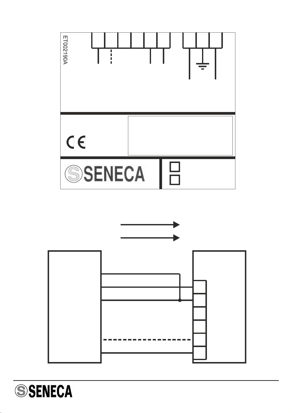
- Output: 0..20 mA
- View scale: 0..19,99
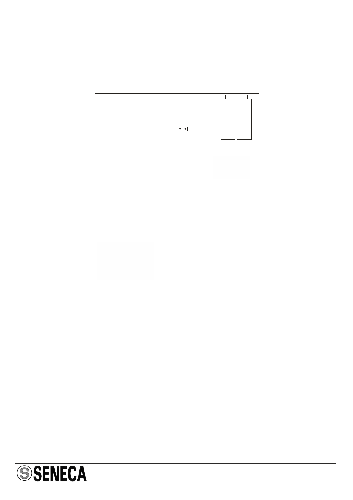
Decimal Point Selection :
P1: one decimal, P2: two decimals
P3: three decimals
SETTING OF THE DECIMAL POINT
Three jumpers, placed in the rare of the frontal panel, define the position of the decimal
point:
FA TORY SETTINGSC
SENECA s.r.l.
Via Austria, 26 - 35127 - PADOVA - ITALY
Tel. +39.049.8705355 - 8705359 - Fax +39.049.8706287
e-mail: info@seneca.it - www.seneca.it
THE INTERNATIONAL CERTIFICATION NETWORK
R
ISO9001-2000
Thisdocumentisproperty ofSENECAsrl.Duplicationandreprodutionareforbidden,ifnotauthorized.Contents
ofthepresentdocumentationreferstoproductsandtechnologiesdescribedinit.Alltechnicaldatacontainedinthe
documentmaybemodifiedwithoutpriornoticeContentofthisdocumentationissubjecttoperiodicalrevision.
DisposalofElectrical&ElectronicEquipment(ApplicablethroughouttheEuropeanUnionand
otherEuropeancountrieswithseparatecollectionprograms)
This symbol, found on your product or on its packaging, indicates that this product should not be
treated as household waste when you wish to dispose of it. Instead, it should be handed over to an
applicable collection point for the recycling of electrical and electronic equipment. By ensuring this
product is disposed of correctly, you will help prevent potential negative consequences to the
environment and human health, which could otherwise be caused by inappropriatedisposal of this
product. The recycling of materials will help to conserve natural resources. For more detailed
information about the recycling of this product, please contact your local city office, waste disposal
serviceorthèretailstorewhereyoupurchasedthisproduct.
P3 P2 P1