MI002273-E ENGLISH 7/8
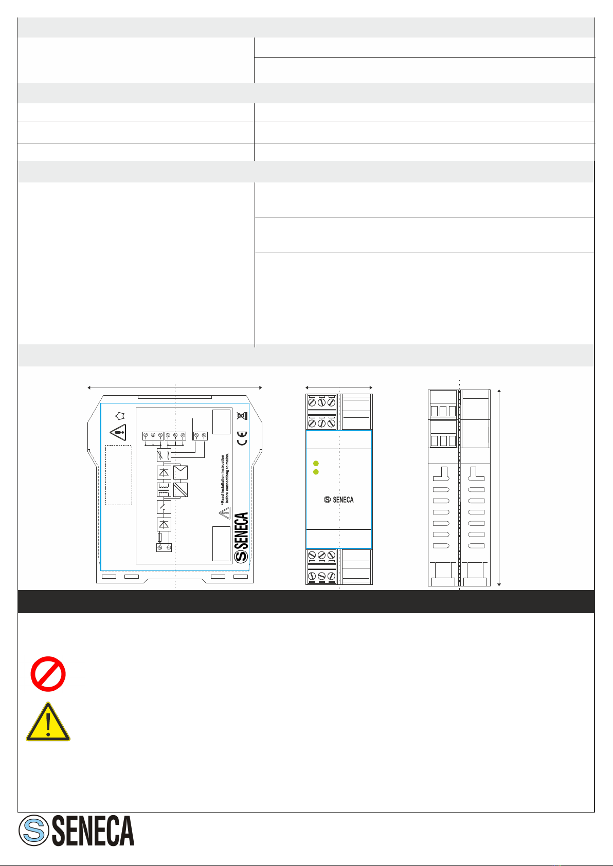
24 Vdc output is ON and regulated
24 Vdc output is disabled
GOOD
PWR
7 8 9
Z-SUPPLY
1 2 3
4 5 6
Input M1,M3:
100.. 240 Vac
50.. 60 Hz
Output M7,M10:
24 Vdc
1,5 A
10 11 12
7 8 9
1 2 3
4 5 6
10 11 12
S
Z-3AO
Pwr
Err
7 8 9
1 2 3
4 5 6
10 11 12
S
Z-TWS3
Run
Act Lnk
Rx
Tx
UP TO 15
MODULES
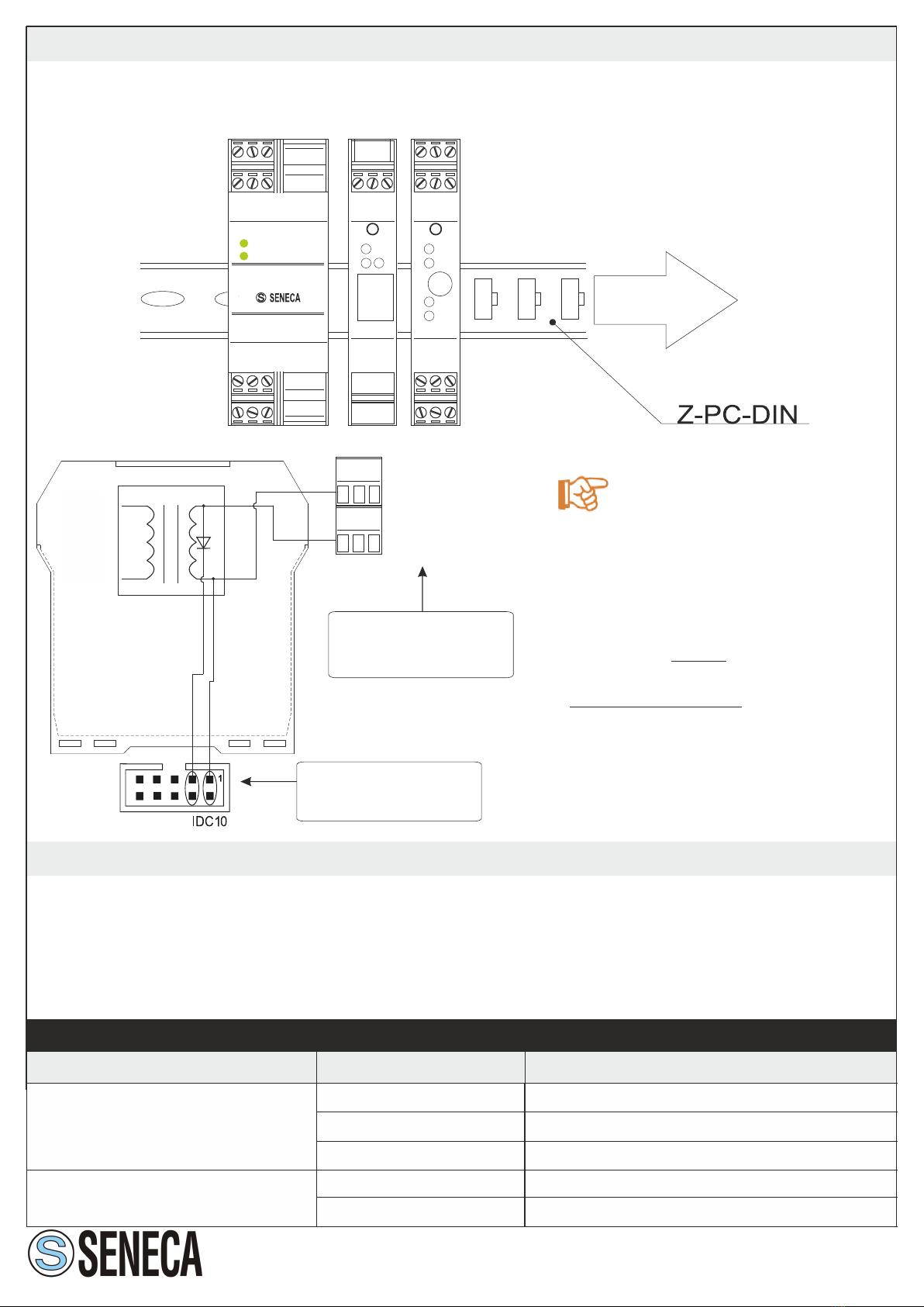
Fig. 5
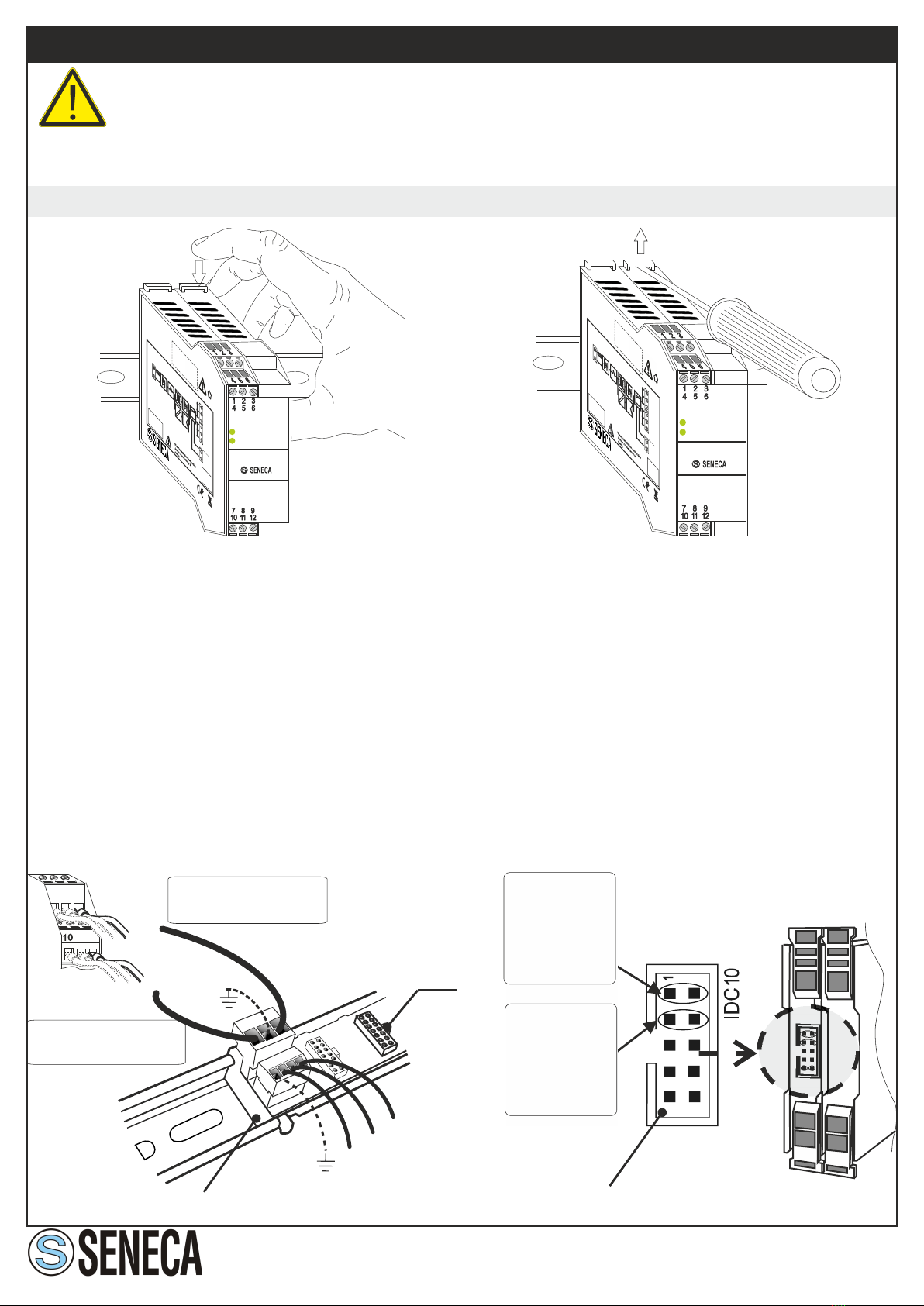
Before using 24 Vdc output through IDC10 connector, see Fig.1d and in Fig.1c. Through
IDC10 connector, Z-SUPPLY can power up to 15 modules.
6.3 24 Vdc-output by IDC10 for Seneca modules
As you can see in the fig.6, there is a
diode internally connected at the end
of the IDC10 output: so, it is possible
to connect more Z-SUPPLY modules
in parallel ONLY if the redundant
outputs are connected by IDC10.
IT IS FORBIDDEN to connect more
Z-SUPPLY modules in parallel using
the redundant outputs by screw
terminals (in alternative, connect a
diode at the end of the output, for
each Z-SUPPLY, externally).
All the connection shown in
fig.6 are internal, into the Z-
SUPPLY.
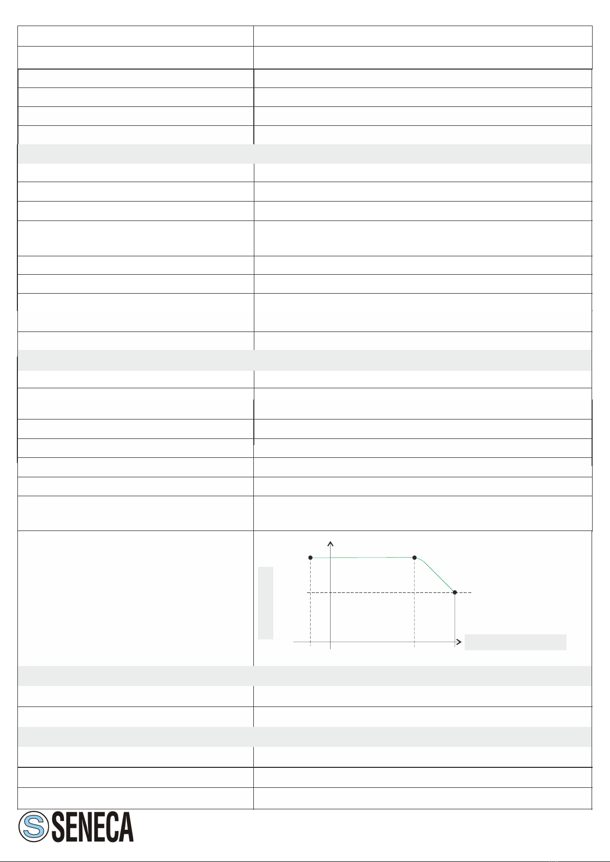
6.4 Output relay and «power good»
The output voltage equal to 24 Vdc is guaranteed by an internal relay, which enables the
output voltage only if the voltage between its terminals is greater than 23.5 V. If the output
voltage is supplied correctly, the LED «good» will be on; otherwise, if a over-loading occurs,
the LED «good» will be blinking. The relay contacts are available on the screw terminals M4
(normally open) and M6 (common).
0 V
Fig. 6
-
++24 V
1112
10
89
7
OK
REDUNDANCY
NO
REDUNDANCY