Senect PS User manual

1
Manual
Sensors
PS
EPS
O2S
pH XR1
ORP XT1
CON
TMP
Version 1.00
From FW Version 1.90 - 27.04.2022

2
Manufacturer:
SENECT GmbH & Co. KG
An 44 –Nr. 11
76829 Landau / Deutschland
Important note:
Please read this manual carefully and store it so that you can use it later. Read the
warning and safety notes attentive.
Further information and latest software releases or documents can be
downloaded from:
www.senect.de
www.produkte.senect.de
© SENECT GmbH & Co. KG

3

4
Index
Index .......................................................................................................................4
Type description ..................................................................................................... 5
General safety instructions.....................................................................................6
Intended use........................................................................................................... 8
Scope of delivery..................................................................................................... 9
Installation ............................................................................................................10
Getting started......................................................................................................12
Sensor –Water level PS & EPS..........................................................................13
Sensor –Pressure EDS ......................................................................................17
Sensor –Oxygen O2S........................................................................................19
Sensor pH XR1 & Redox XT1 .............................................................................23
Sensor - Conductivity CON................................................................................27
Sensor –Temperature TMP & DUO.................................................................. 29
Calibration of sensors ...........................................................................................30
Menu –Sensors in SENECT® OS............................................................................ 37
Technical data....................................................................................................... 42
Information about the correct disposal................................................................53
Guarantee.............................................................................................................53
Notes..................................................................................................................... 54

5
Type description
Art.-No.:
Name:
Type:
2000
Sensor - Water level sensor EPS
EPS-250-MA
2001
Sensor - Water level probe PS
PS-300-MA
2002
Pressure sensor EDS 6 bar
EDS-6000-MA
2003
Pressure sensor EDS 2.5 bar
EDS-2500-MA
2004
Pressure sensor EDS 250 bar
EDS-250B-MA
2100
Sensor - Oxygen O2S
O2S-20-SC
2100-PP
Sensor - Oxygen O2S PP housing
O2S-20-SC-PP
2200
Sensor - pH XR1
PH-410-XR1-SC
2300
Sensor - ORP XT1
ORP-1-XT1-SC
2400
Sensor - Conductivity CON 50 mS/cm
CON-50-SC
2410
Sensor - Conductivity CON 2 mS/cm
CON-2-SC
2420
Sensor - Conductivity CON 10 mS/cm
CON-10-SC
2450
Sensor - Conductivity CON 500 mS/cm
CON-500-SC
2500
Sensor - Temperature TMP PT1000
TMP-50-SC
2501
Sensor - Temperature TMP-DUO
DUO-50-SC
2502
Sensor - Temperature TMP int. transducer
TMP-50-SC-IT

6
General safety instructions
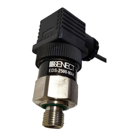
The SENECT pressure sensor EDS is an electronic sensor unit for measuring the pressure in
pipelines, hoses or vessels.
As this is an electronic product, the usual requirements, as with all electrical
appliances, must be met. The device may only be operated with compatible
control units or control units approved by SENECT. The device and all
connected lines must be installed and operated protected from moisture
and wetness. When laying all cables, care must be taken that no safety-
relevant impairments such as tripping hazards occur. For many applications,
fuse protection by a residual current circuit breaker with a tripping current
< 30 mA is mandatory. Find out more about this.
The device must be installed protected from overheating by direct sunlight and must only
be operated at an ambient temperature between 0°C and +40°C. The device must not be
modified, except for extensions or software updates of SENECT®. It is forbidden to open
the device or to penetrate the inside of the housing in any way.
The pressure sensor EDS is not intended to be used by persons (including children) with
limited physical, sensory or mental abilities or for lack of experience and/or knowledge,
unless they are supervised or instructed by a person responsible for their safety on how
to operate the device. Please keep these instructions for use as a reference. Technical and
optical changes as well as printing errors reserved.

7
Symbols and signal words
DANGER!
Warning of life-threatening dangers.
WARNING!
Warning of possible life threatening and / or severe irreversible
injuries.
ATTENTION!
Warning of possible medium or slight injury.
ATTENTION!
Follow the notes to avoid damage of equipment
NOTE!
Further information for the use of the device!
ATTENTION!
Warning of electrical shock.

8
Intended use
The SENECT® sensor is designed to measure the respective parameter in water. The
measuring range, resolution and accuracy can be found in the following table.
All SENECT® sensors are designed for the use in industrial aquaculture applications.
Type:
Measured value / Remark
Measuring range
Resolution
EPS-250-MA
Water level in tanks, sensor screwed in
0 –250 mbar /
0 –250 cm
0,1 mbar
0,1 cm
PS-300-MA
Water level, sensor submerged
0 –300 mbar /
0 –300 cm
0,1 mbar /
0,1 cm
EDS-6000-MA
Pressure of gaseous media (air,
oxygen) or liquid media (water) in
pipelines or containers
0 –6000 mbar
1 mbar
EDS-2500-MA
0 –2500 mbar
1 mbar
EDS-250B-MA
0 –250 bar
1 bar
O2S-20-SC
O2S-20-SS
Concentration of dissolved oxygen,
Water temperature
0 –400 % a.s.
0 –40°C
0,1 % a.s.
0,1 °C
PH-410-XR1-SC
pH-value in water
pH 4 –pH 10
0,01 pH
ORP-1-XT1-SC
Oxidation-reduction potential (ORP or
redox potential)
-2000 –
+2000 mV
1 mV
CON-50-SC
Electrical conductivity in water,
temperature.
An integrated temperature sensor
provides temperature compensation
so that the displayed values refer to
the temperature-corrected
conductivity at 25°C.
0 –50 mS/cm
0 –40 °C
0,01 mS/cm
0,1°C
CON-2-SC
0 –2 mS/cm
0 –40 °C
1 µS/cm
0,1°C
CON-10-SC
0 –10 mS/cm
0 –40 °C
0,01 mS/cm
0,1°C
CON-500-SC
0 –500 mS/cm
0 –40 °C
0,1 mS/cm
0,1°C
TMP-50-SC
TMP-50-SC-IT
Temperature in water
0 –50 °C
0,1 °C
DUO-50-SC
Temperature in water
Temperature in air
0 –50 °C
-10°C –50 °C
0,1 °C
0,1 °C

9
Scope of delivery
Sensor type
Delivered Items
Conductivity Sensor CON
1 x Conductivity Sensor CON
1 x Manual
Pressure Sensor EDS
1 x Pressure Sensor EDS incl. connection cable
1 x Manual
Water level Sensor EPS
1 x Water level Sensor EPS
1 x Manual
Oxygen Sensor O2S
1 x Oxygen Sensor O2S
1 x Manual
ORP Sensor XT1
1 x ORP Sensor XT1 electronic interface
1 x ORP Sensor XT1 electrode
1 x ORP Calibration-Solution (+475 mV)
1 x Calibration-BNC-plug (0 mV)
1 x Manual
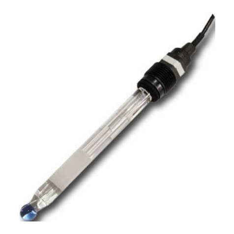
pH Sensor XR1
1 x pH Sensor XR1 electronic interface
1 x pH Sensor XR1 electrode
1 x pH Calibration-set (pH 4 and pH 10)
1 x Manual
Water level probe PS
1 x Water level probe PS
1 x Manual
Temperature Sensor TMP
1 x Temperature Sensor TMP (incl. electronic interface)
1 x Manual
Temperature Sensor DUO
1 x Double Temperature Sensor DUO (incl. electronic
interface)
1 x Manual
Please check directly after delivery, that the package is not destroyed or
damaged or was opened before. Please check also, that all parts as listed
above are included. If anything is missing or broken, please contact us as
soon as possible within 14 days. Unfortunately, we cannot accept later
information of damage, which happened during the transport.

10
Installation
Choose a place for the electronic interface (electronic unit protected by
black silicone casing) which is clean, dry and protected from direct sunlight.
Ensure that all cables are placed safely and all regulations are fulfilled.
Mount the sensor so that the sensor head is permanently submerged. This can be
achieved, for example, by attaching it using suction cups or, if the water level fluctuates
greatly, by attaching it to a float. Alternatively, the sensors can also be installed in the pipe
system (e.g. within a measuring chamber).
Figure 1: Example of the installation of the oxygen sensor
Figure 2: Example of mounting an electrode in a flow chamber or float

11
Figure 3: Mounting sensor CON in a pipeline
To increase the service life, the sensor can be mounted so that the upper
part of the sensor and the cable are not submerged. This can be achieved
either by mounting using brackets or suction cups, or by mounting on a float
if the water level fluctuates greatly.
Important Note: Sensor EPS
The Water level sensor EPS must not be submerged. Use the submersible water level
probe PS for this purpose.

12
Getting started
Short version
1. Attach the probe to the measuring point.
2. Mount the electronic interface at a protected location.
3. Connect the sensor cable with a control unit (plug „SENSOR“).
4. The control unit recognizes the sensor and starts the measurements.
The menu may differ depending on the software version used.
Updates to these operating instructions can be found at
www.senect.de.

13
Sensor –Water level PS & EPS
EPS:
Mount the water level sensor screwed in (either with seal and lock nut or with sealing tape
and matching thread in the container wall) in a container or in a filter chamber (when used
to control drum or belt filters).
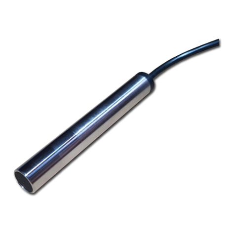
PS:
Attach the water level probe submerged at the desired location in the filter (if the water
level probe is to be used to control a drum or belt filter) or in the pond / basin. The probe
must be firmly anchored in a location with low currents to avoid interference.
It is important to ensure that the connector is kept permanently dry, as this
is where the pressure equalization with the atmosphere takes place. Please
note that there is a capillary in the cable for pressure equalization and
therefore a minimum bend radius of 15 cm is required.
Connect the connection cable to your control unit at one of the sensor slots marked in
blue. The SENECT control units automatically detect the water level sensor and start
operation.
1. Assign the type of sensor in the menu under Sensors / Plug X / Sensor Type (EPS-
250-MA or PS-300-MA).
2. To assign a function to the water level sensor, select the place of use under
Sensors / Plug X / Position. This is linked to a respective function:
-Pre-chamber: The water level sensor is used to control filters in pumped
version and is installed in the filter pre-chamber.
-Filter: The water level sensor is installed behind the drum or belt in filters
and is used to control the filter in gravity mode.
-Refill sensor: The water level sensor is used to refill water in the pond or
basin.
-Other: The water level sensor is not assigned to any of these functions
and can be assigned a function via the Outputs menu.
3. To set the measured value to 0cm (reference the sensor), select Sensors / Plug /
Sensor referencing.

14
Water level probe –Controlling particle filters
The optimal location for the PS level probe for filter control is where the
level of pollution of the filter mesh is "measured" and where it is also
possible to check the function of the circulation pump. In gravity systems
this is usually behind the filter or in the filter chamber, while in pumped
systems it is in front of the drum filter or in the pre-chamber of the filter.
Figure 4: The locations of the water level probe when a drum filter is to be controlled. Please note,
that in the gravity mode, the PS is in the filter chamber, while in pumped mode, the PS is installed in
the pre-chamber.

15
The cleaning of drum or belt filters can be triggered depending on the contamination by
measuring the water level. A distinction must be made here as to whether a rise or fall in
water level should trigger cleaning. In gravity mode (see Figure 4 ), the probe is mounted
in the filter chamber and a drop in the water level triggers cleaning.
In pumped mode, the probe is installed in the pre-chamber and a rising water level triggers
the cleaning.
Therefore, select one of both variants for your filter control.
Differential operation: Use two water level probes to control the filter operation via the
water level difference between the pre-chamber and filter chamber, assign the water level
probes to the position where the probes are located. If the pre-chamber and filter
chamber are selected, cleaning triggering takes place automatically according to the water
level difference.
After selecting the position(s), trigger a filter cleaning with the CLEAN FILTER key and then
set the water level to "0 cm" with the "Reference sensor" menu item. Now the relative
water level is set to "0 cm" (the absolute water level always refers to the actual installation
depth of the probe).
Now you can adjust further filter settings.
Figure 5: Difference between relative and absolute water level. The relative water level is used for
control purposes (e.g. control filter, refill water) while the absolute water level is used for alarming.
reference zero level
absolute water level
(used for alarming,
e.g. +48 cm)
relative water level
(used for filter
operation, e.g. -5 cm)

16
Water level probe –Refilling water level
Select "Refill sensor" as the position and place the probe in your pond or basin. Set the
water level to "0 cm" with "Reference sensor". With the position "Refill sensor" the sensor
value is additionally displayed in the app as "Pond" in the filter sensor values field.
You can move the "0 cm" line in the menu under "Change zero-point". Positive values (e.g.
+5 mm) move this line upwards while negative values (e.g. -2 mm) move this line
downwards.
Now you can set the other water refill settings. For the FILTER|CONTROL unit you will find
them in the water refill menu while for the other controllers you must use the "Sensor
control" function.
Water level probe –Other position
If you want to use the water level only for monitoring or to do a sensor contro select as
the position "Other". You can then set the alarm thresholds. Please note that these
thresholds refer to the absolute water level. You can change to the referenced water level
in the alarm threshold menu.

17
Sensor –Pressure EDS
The sensor is screwed into a suitable thread using the pressure sensor-side G1/4" threaded
nipple.
Seal the thread with sealing tape or a suitable and approved sealing
compound (e.g. Loxeal 58-11, BAM-approved Teflon tape). Make sure never
to touch the sensor membrane (not even for cleaning purposes) and that
the cable connection side must be kept permanently dry, as this is where
the pressure equalization to the atmosphere takes place.
Connect the supplied connection cable to the sensor and your control unit at one of the
sensor slots marked in blue. The SENECT control units automatically detect the sensor and
start operation.
1. Select the correct sensor type under Sensors / Plug X / Sensor type (EDS-2500-
MA).
2. Enter the measuring range of your sensor in mbar (e.g. 2500 mbar) in the
submenu Sensors / Plug X: EDS / Measuring range.
The sensor is now ready for use and you can make further settings. For further
information, please refer to the manual of your SENECT controller.

18
Application example
The pressure sensor EDS can be used to monitor the line pressure of the ventilation line
(oxygen or compressed air). If there is a fault in this supply line (tank empty, generator
defective, leakage), the EDS can trigger an alarm if the pressure falls below the set lower
threshold value.
Apply the following settings:
-Sensor / Plug X: EDS / Alarm / Lower Threshold: e.g. 1500 mbar
-Sensor / Plug X: EDS / Alarm / Upper Threshold: e.g. 2000 mbar
-Sensor / Plug X: EDS / Alarm / Hysteresis: e.g. 10 mbar
These settings trigger an alarm when the pressure drops below 1500 mbar or exceeds
2000 mbar.

19
Sensor –Oxygen O2S
Remove the blue protective cap of the sensor and attach the sensor. The probe itself must
be suspended in the water so that the membrane is permanently submerged.
To increase the service life, the sensor can be mounted so that the upper
part of the sensor and the cable are not submerged. This can be achieved
either by mounting using brackets or suction cups, or by mounting on a float
if the water level fluctuates greatly.
Please consider when selecting the mounting location that in surface waters like fish ponds
the solar radiation can lead to a thermal stratification of the water body, associated with
strong gradients in dissolved oxygen
Protect your sensor from fish biting on the sensor membrane! SENECT offers
protection cages.
The oxygen sensor O2S-20-SC-PP already has a protection cap.
Connect the blue marked plug of the sensor with a sensor input port (also blue marked) of
your control unit. The SENECT control units recognize the sensor itself and start
automatically the measurements. Take into account that the measurement interval is set
to 30 s to elongate the lifetime of the sensing cap.
The oxygen sensor O2S is factory calibrated and need to be recalibrated –under for
aquaculture typical environmental conditions –earliest 6 months.

20
Recalibration intervals
Recalibration of the sensor is regularly recommended every 6 months. To determine if a
calibration is necessary, hold the sensor in air (preferably with 100% humidity) for a few
minutes. If the sensor shows about 100% oxygen saturation (usually this value is just below
100% due to insufficient humidity), no calibration of the upper calibration point is
necessary. Repeat this procedure for the lower calibration point, keeping the sensor in 0%
O2 solution. If the sensor indicates approx. 0%, no recalibration is necessary for this point
either.
Membrane wear
Since the fluorescent membrane fades due to the measurement, we recommend replacing
the sensor cap (Art. No.: 2101, Type: O2S-ATK), which contains the photoreactive
membrane, at intervals of three years. To do this, simply unscrew the cap and replace it.
The sensor must always be recalibrated after replacing the cap!
Cleaning
If algae or microorganisms grow up, the sensor membrane must be cleaned regularly. It is
best to remove soiling or growth carefully with a cotton swab and water. If the membrane
is more heavily soiled, you can also use diluted acetic acid.
Avoid contact with organic solvents such as toluene, acetone or
chloroform at all costs. These solvents can cause damage to the
membrane! Steam sterilization can also damage the sensor.
Disinfection
The sensor can be disinfected with peracetic acid (max. 5 mg / l), methanol, ethanol,
isopropanol or 3% H2O2 solution. Rinse the sensor afterwards with tap water.
This manual suits for next models
23
Table of contents
Other Senect Accessories manuals
Popular Accessories manuals by other brands

Reimo
Reimo TAVIRA AIR 390 installation instructions
Intermatic
Intermatic AG4803C installation instructions
SunSynk
SunSynk POCKET POWER STATION 2 user manual
Meteor
Meteor Whiz 2.0 installation instructions
Omron
Omron ZW-8000 Series user manual
Oliver Kessler
Oliver Kessler SOLITAIRE PUNKAH Installation & owner's manual
