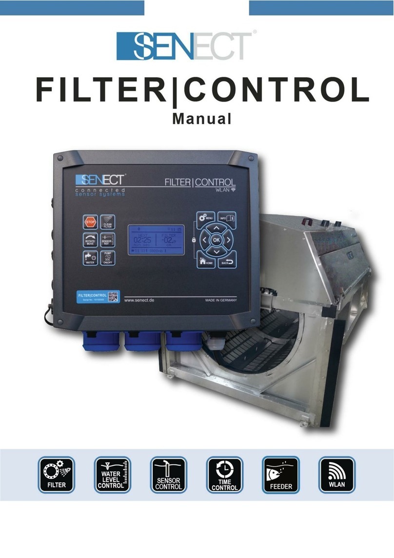
Senect AQUACULTURE Series User manual


Product type
2
Product type
Product
name:
SENECT®AQUACULTURE|CONTROL
150 W / 300 W
Versions:
AQUACULTURE|CONTROL –Basic (150 W)
AQUACULTURE|CONTROL –Basic (300 W)
AQUACULTURE|CONTROL –Pro (150 W)
AQUACULTURE|CONTROL –Pro (300 W)
Type:
AQC-A1-333-150
AQC-A1-333-300
AQC-A1-663-150
AQC-A1-663-300
Producer:
SENECT GmbH & Co. KG
An 44 –No. 11
76829 Landau / Germany
Important note:
Please read this manual carefully and store it so that you can use it later. Read the warning and safety
notes attentive.
More information and latest software releases or documents can be downloaded from:
www.senect.de
Further information, application descriptions and answers to frequently asked questions can
be also found on the SENECT Forum:
http://forum.senect.de/phpbb/
© SENECT GmbH & Co. KG - FW 00.80

Table of contents
3
Table of contents
Product type............................................................................................................................................ 2
Table of contents..................................................................................................................................... 3
Used symbols and wording ..................................................................................................................... 4
General Security Notes............................................................................................................................ 4
Intented use ............................................................................................................................................ 5
Performance specification....................................................................................................................... 6
Getting started ........................................................................................................................................ 7
Scope of delivery ................................................................................................................................. 7
Installation and start-up...................................................................................................................... 7
Using the AQUACULTURE|CONTROL to switch outputs as a function of sensor measurements ...... 9
Controlling the drum filter with the AQUACULTURE|CONTROL....................................................... 11
Using the AQUACULTURE|CONTROL to switch outputs as a function of sensor measurements –
Short version ..................................................................................................................................... 16
Controlling the drum filter with the AQUACULTURE|CONTROL –Short version ............................. 17
Operation .............................................................................................................................................. 19
Display and symbols.......................................................................................................................... 19
Buttons and menu............................................................................................................................. 20
The Menu .............................................................................................................................................. 22
Filter settings..................................................................................................................................... 26
Sensor Menu ..................................................................................................................................... 30
Menu output ports and 230 V AC plugs............................................................................................ 32
Description of the major output functions ....................................................................................... 33
Additional functions .......................................................................................................................... 37
Menu WLAN ...................................................................................................................................... 40
Menu System Settings....................................................................................................................... 46
Technical data ....................................................................................................................................... 48
Information about the correct disposal ................................................................................................ 48
Guarantee.............................................................................................................................................. 48

Used symbols and wording
4
Used symbols and wording
DANGER!
Warning of life threatening dangers.
WARNING!
Warning of possible life threatening and / or severe irreversible
injuries.
ATTENTION!
Warning of possible medium or slight injury.
ATTENTION!
Follow the notes to avoid damage of equipment.
NOTE!
Further information for the use of the device.
NOTE!
Further information for the use of the device.
General Security Notes
The SENECT® AQUACULTURE|CONTROL is an electronic control unit developed for measuring
and controlling water quality parameters and actuator like fish feeders, valves or drum filters.
Since it is an electric product the common prerequisites for a safe instrument usage
must be fulfilled. The device must be operatated with 230 V AC (~50 Hz). Ensure
that all cables are installed safely so that no obstacles for persons are built and all.
Mount all cables and electric devices protected against direct environmental
impacts like overheating by direct sunlight and water. Even if the product is
protected against spray water, the product´s lifetime will be elongated, if it is
mounted on a protected place.
For many applications a ground fault circuit interruper (interrupting current <= 30 mA) is
required by law. Inform yourself about the valid legislation. If the mains plug cable is damaged,
only the producer or a qualified person designated by the producer is allowed to repair the
damage.

Intented use
5
The operating temperature of the device must be between 0°C and +40°C. It is not allowed to
modify the SENECT® AQUACULTURE|CONTROL, to open the housing or to insert anything into
the housing.
If the power cable is damaged, it must be replaced by the producer or a qualified person
designated by the producer to avoid potential dangers.
The device is designed to be operated by professional users. It can be also operated by
children over the age of 8 years and persons with limited physical, sensorial or cognitive
ability, if they are supervised, trained in the operation of the device, able to operate the device
safely and if they understand potential risks resulting from the operation. It is for children or
persons with limited physical, sensorial or cognitive ability not allowed to perform any
maintenance works.
Please store this manual. We suggest the storage a copy of the manual in the vicinity of the
device.
Technical and optical changes of this manual are subject to alterations.
Warning: Before doing any maintenance work switch off all electric devices or unplug
the mains plug.
Intented use
The AQUACULTURE|CONTROL is an electronic control and measurement unit developed to
measure water quality parameters and control processes in professional industrial
aquaculture facilities.

Performance specification
6
Performance specification
The SENECT AQUACULTURE|CONTROL is a versatile measurement and control unit designed
for the use in aquaculture. There are four different versions available:
AQUACULTURE|CONTROL
Basic
150 W
Basic
300 W
Pro
150 W
Pro
300 W
Sensor input ports
3
3
6
6
Actuator output ports
2 (max. 1 A)
2 (max. 1 A)
5 (max. 1 A)
5 (max. 1 A)
24 V DC PWM, 4-
20 mA, 0-10 V
24 V DC PWM, 4-
20 mA, 0-10 V
24 V DC PWM, 4-
20 mA, 0-10 V
24 V DC PWM, 4-
20 mA, 0-10 V
High-power-
actuator output ports
1 (max. 5 A)
1 (max. 10 A)
1 (max. 5 A)
1 (max. 10 A)
24 V DC PWM
24 V DC PWM
24 V DC PWM
24 V DC PWM
230 V AC mains plug
3
(max. 8 A, 2 A, 4 A)
3
(max. 8 A, 2 A, 4 A)
3
(max. 8 A, 2 A, 4 A)
3
(max. 8 A, 2 A, 4 A)
Every type of SENECT sensor can be connected to the universal sensor input ports (e.g. the
oxygen sensor O2S, the pH sensor XR-1 or the water level probe PS). The
AQUACULTURE|CONTROL measures then the signal of the connected sensors, saves the
measurements internally (up to max. 3 months) and can control output ports depending on
the sensor readings or send alarm message, if the control unit is connected to the internet.
At its actuator output ports, 24 V DC actuators like valves or fish feeders can be connected
directly. Also actuators, which can be controlled via 4-20 mA or 0-10 V control signals can be
controlled directly. Actuators with 230 V AC can be switched with the actuator ports by using
the optional PowerSwitch SC24-230 or can be controlled directly, when they are connected to
one of the three 230 V AC output ports at the bottom side of the device. Please consider
always the max. allowed power consumption of actuators.
The AQUACULTURE|CONTROL can also be used to control drum or belt filters. Pleas consider
here:
The direct control of drum or belt filters is only possible for filter with a 24 V DC filter
motor with max. 5 A (AQC-A1-xx3-150) or 10 A (AQC-A1-xx3-300) or with a 230 V AC
filter motor. The spray pump must be operated with 230 V AC with a maximal
current of 8 A. For enabling all functions which need to adjust the motor speed of the filter
(e.g. intensive cleaning), 230 V or 400 V filter motors must be controlled via a variable
frequency drive connected to one of the actuator output ports (see Fig. 5).

Getting started
7
The integrated WLAN module can be used to embed the SENECT AQUACULTURE|CONTROL
into a WLAN network. With an established internet connection of the
AQUACULTURE|CONTROL, the control unit can download software updates and send alarm
messages. Additionally, with the SENECT Control App on an Android, Apple iOS or Windows
device, the AQUACULTURE|CONTROL can be operated remotely (Internet connection with
port forwarding and dynamic DNS necessary, for more details see chapter WLAN).
Please consider during the design of your control system that the sensors, cables and
actuators are not within the scope of delivery of the AQUACULTURE|CONTROL and have to
be ordered separately.
Getting started
Scope of delivery
o1 x AQUACULTURE|CONTROL unit with 3 m power cable
o1 x Wall mount set
o1 x Set of exchange fuses with 2 AT, 4 AT and 8 AT
o1 x Manual
Note
Please check directly after delivery, that the package is not destroyed or damaged
or was opened before. Please check also, that all parts as listed above are included.
If anything is missing or broken, please contact us as soon as possible within 14 days.
Unfortunately, we cannot accept later information of damage, which happened during the
transport.
Installation and start-up
Choose a place for your AQUACULTURE|CONTROL which is clean, dry and protected
from direct sunlight. Ensure that all cables are placed safely and all regulations are
fulfilled.
To mount the AQUACULTURE|CONTROL, place the delivered wall mounting parts on the back
of the device. Tight the parts with the delivered screws (3 x 10 mm, see Fig. 1). Afterwards,
you can use the wall mounting parts of the AQUACULTURE|CONTROL to attach the device to
its place, e.g. on a wall.
Plug the 230 V power plug of the AQUACULTURE |CONTROL in a spray water protected plug
(IPx4 or higher) but do not switch the AQUACULTURE |CONTROL on yet. The next steps inform
you how to connect the sensors and actuators.

Getting started
8
Fig. 1: Wall mounting parts and dimensions of the drill holes for the mounting of the AQUACULTURE|CONTROL.
Fig. 2: Sensor and actuator ports of the AQUACULTURE|CONTROL Pro. The AQUACULTURE|CONTROL Basic is equipped
without the upper row (SENSOR 4-6 and OUT 4-6).

Getting started
9
Using the AQUACULTURE|CONTROL to switch outputs as a function
of sensor measurements
Which sensors, which actuators and how the cables are conneced depend strongly on your
application. In general, you can follow these steps:
1. Mount sensors and actuator at their location.
2. Place and lay the cables safely to the AQUACULTURE|CONTROL, remove the
protection cap from the sensor input port and connect the sensor plug to the blue
marked „SENSOR“ input.
3. Switch on the AQUACULTURE|CONTROL and set the desired settings. To switch the
output ports, you have to assign a function to the selected output port.
Fig. 3: View from the bottom side of the AQUACULTURE|CONTROL.
Note: Changing languages can be easiliy done in the menu. Press the button MENU
and select under „System Einstellungen / Sprache“ the language „English“.

Getting started
10
Application example: Oxygen control
In this example, the oxygen sensor O2S is connected to SENSOR 1 and the „normally opened“
solenoid valve (Type: MVO-M7-SC, Art. No.: 3020) is plugged into actuator plug OUT 1.
(„Normally open“ is selected here, that in case of a power shutdown the valve opens
automatically and the fish still get oxygen.)
The desired oxygen level should be over 95% and if 100% are reached, the addition of oxygen
shall be stopped. Go to the menu (MENU / Output Ports / Plug 1) and set:
Function: Sensor Control –a new submenu appears (when you go back in the
menu)
In the submenu „Sensor Control“ set:
oControl Parameter: O2 % a.s.
oSensor Plug: 1
oStart value: 95%
oStop value: 100%
oMax. Duration: 00:00:00
oBreak Time: 00:00
In the submenu „Output signal“ set:
oPolarity: Low Active (the output is switched off, when the O2
concentration falls below 95% so that the [normally open] valve opens)
Now, all the settings are done and you can test the system, e.g. dipping the O2S sensor in
0-%-oxygen solution.

Getting started
11
4. Optional: Connect the AQUACULTURE|CONTROL with your WLAN network (see
chapter: WLAN).
5. Check the function of your control settings. Hint: You can easily check the actuator by
selecting the function „Constant on“.
Now, your system is ready for useage.
Controlling the drum filter with the AQUACULTURE|CONTROL
When you want to control a drum or belt filter with the AQUACULTURE|CONTROL follow the
steps below:
1.) Water level sensor installation
If you do not have a water level sensor, please continue with 2.).
Mount the water level probe or sensor at its the optimal location. The optimal
location of the water level sensor (PS-300-MA or EPS-250-MA) is where the water
level responds to the clogging of the filter and a control over the proper functioning
of the circulation pump is. In a gravity system, this location is usually behind the filter while
in pumped systems, this is typically before the filter or in the pre-chamber of the filter.
Please do not insert the water level sensor deeper than 2.5 m and ensure that it is well fixed
and at a location with low direct currents. Read also the instructions of the water level sensor
manual.
Connect the water level sensor cable to the AQUACULTURE|CONTROL (e.g.) with SENSOR 1
(see Fig. 2). If you are using a second water level sensor, connect the 2nd probe with SENSOR 2.
2.) Case switch
If your filter is equipped with a case or cover proximity switch, you can connect it to SENSOR 3.
If you do not have a suitable plug at your switch, you can order the proper plug from SENECT
or your dealer.
The function of the case switch is to switch off the drum motor and a connected UVC lamp
(which are often located inside the drum filter), when the cover is opened (mode: drum filter).
In the mode “belt filter” is selected, then only the UVC lamp is switched off.
Please consider that the case or cover switch does not fulfil all requirements to be an
emergency stop switch according to EN ISO 13850:2015-10.

Getting started
12
Fig. 4: Connecting an open channel drum filter and a boxed drum filter. Please note that the filter motors here are
controlled by the high-power acuator output port OUT 3.

Getting started
13
3.) Filter motor
24 V DC Filter motors:
Ensure that the filter motor is correctly installed at your filter and check in the technical
documentation, if the motor can be operated with 24 V DC (max. current 5 or 10 A). If yes,
you can connect the motor with the optional available motor cable (Art. No.: 3400, polarity:
red = +, black = -). Connect the motor cable plug to the high-power actuator output port
OUT 3.
230 V AC Filter motors:
If your filter is equipped with a 230 V AC motor, connect its plug with the main plug 2 (230 V
OUT 2). Please consider that only motors with a power of max. 500 W can be connected
directly here. Motors with a higher power consumption can be connected to the other two
230 V PLUG 1 or 230 V PLUG 3, in case these are not needed for other consumers like a spray
pump or can be connected to actuator output ports via the optional Power Switch 24-230 (Art.
No.: 3100).
Note here, that all functions where the motor speed is controlled by the
AQUACULTURE|CONTROL do not work, because there is just an on / off switching of the filter
motor possible. These functions are:
Intensive cleaning programme
Soft motor start
High-pressure cleaning mode
If you want to use these functions with AC motors, you need a variable frequency drive to
control the motor speed.
230 V / 400 V AC Filter motors connected via variable frequency drive (VFD):
For changing the rotation speed of AC filter motors, which allows to use all functions which
change the motor speed, a variable frequency drive between the AQUACULTURE |CONTROL
and the filter motor is necessary.
SENECT offers fully parametrized and wired VFDs. The green labelled actuator cable from the
VFD must be connected to one the actuator output ports, e.g. OUT 1.

Getting started
14
Fig. 5: Connecting a drum filter via a variable frequency drive.
Note: Select the function “filter motor” for the corresponding actuator output port
(here OUT 1) and select the additional function “variable frequency drive”.
4.) Connecting the spray and circulation pump
If the pumps are correctly installed, arrange all cables safely to your
AQUACULTURE|CONTROL. Check on the data sheets of your pumps, if they fit to the
specifications of the AQUACULTURE|CONTROL (230 V OUT 1: 230 V AC, max. 1800 W, 230 V
OUT 3: 230 V AC, max. 900 W). Plug the spray pump connector into the plug „230 V OUT 1“
and the connector of the circulation pump to the plug „230 V OUT 3“ (see ).
To operate a drum or belt filter correctly, it is necessary to connect the filter motor
and spray pump according to the specifications of the filter producer.
Every drum or belt filter consumes water. Therefore, it is absolutely necessary
that the lost water is refilled. Ensure that either the water is replenished
automatically or if manually, that the water level in your tanks or ponds is
constant.

Getting started
15
STARTING THE SYSTEM
Switch the AQUACULTURE|CONTROL on with the ON/OFF Switch at the bottom (Fig. 3).
By pressing the button MENU, you can configure all necessary settings. With the cursor
buttons and , you can choose the desired menu item and to confirm your selection, press
OK. The button BACK brings you alway one hierachical level down, while HOME displays the
normal screen and exits the menu.
If your filter is used in a pumped system, select in the Filter Settings as Filter Mode „Pumped
System“. If you are operating the filter in gravity mode, select “Gravity System”.
If you are using a 230 V AC filter motor connected to a 230 V main plug, select in the menu at
230 V Plug / 230 V Plu X the function „Filter Motor”. If you are using a 230 V AC filter motor
connected via a variable frequency drive to an actuator output port, select in the menu at
Fig. 6 Sketch showing the general two hydraulic systems in which drum filter are operated.

Getting started
16
Output ports / Plug X the function „Filter Motor”and the additional function “Var. Frequency
Dri”.
To assign a function to the water level sensor(s), select in the menu Sensors / S X / Position
to the location where the sensor is mounted. Is it in front of the drum, select “Pre-chamber”,
and is it mounted behind the drum, select “Filter-chamber”. The Pre-chamber defined sensor
starts flushing when the water level rises above the flush level, while the definition Filter-
chamber initiates the cleaning, when the water level falls below the flush level.
Check and eventually select the proper type of water level sensor connected to your
AQUACULTURE|CONTROL. If you are using the water level probe PS, select Sensors / S X /
Sensor Type the type: „PS-300-MA” while if you use the water level sensor EPS, select „EPS-
250-MA“.
If you have connected your circulation pump to the AQUACULTURE|CONTROL, assign the
function “Circulation pump” to the corresponding 230 V plug. You can now switch off (and
on) your circulation pump by pressing the button „STOP“.
After connecting your spray / jet / backwash pump to the AQUACULTURE|CONTROL, assign
the function “Spray pump” to the corresponding 230 V plug. If you have it connected via an
PowerSwitch or VFD at one of the actuator output ports, assign the function “Spray pump” to
this port.
Clean the filter by pressing the button „CLEAN FILTER“. After the cleaning process, check the
water level in your system. If the water level is correct, you have to set the water level
sensor(s) to zero (referencing). Go therefore in the menu to Sensors / S X / Sensor Referencing
and confirm with yes. This sets the relative water level to 0 cm (the absolute water level is
always the actual water level measured by the probe, while the relative water level refers to
this set zero condition).
Now, your system is ready for operation.
To achieve the most efficient operation, you have to configure all other filter-related settings
so that they fit to your filter, for example the cleaning duration, etc. You´ll find more
information in the chapter “Operation”.
Using the AQUACULTURE|CONTROL to switch outputs as a function
of sensor measurements –Short version
1. Mount the AQUACULTURE|CONTROL at a protected location.
2. Mount the sensor at its position and connnect the cable to one of the SENSOR plugs.
3. Turn the AQUACULTURE|CONTROL on.

Getting started
17
4. Select in the Menu / Output ports or Menu / 230 V Plug the output, at which the
corresponding actuator (e.g. aerator, valve) will be plugged and select the desired
function. If you want to switch the output in relation to sensor readings, select „Sensor
Control“.
5. Set all the necessary parameters and plug in the actuator.
Note: Do always doublecheck your setted parameters and afterwards the correct operation
of the function.
Hint: By using the function „Constant on“ you can check the function of the actuator.
Controlling the drum filter with the AQUACULTURE|CONTROL –Short
version
1. Mount the AQUACULTURE|CONTROL at a protected location.
2. Mount the water level probe PS submerged in the filter chamber (gravity system) or in
the pre chamber (pumped system). If you are using the water level sensor EPS, install it
at its correct location analogue to the probe PS.
a. In case you are using 2 water level sensors to control your filter backwash by the
difference in water level, install both sensors (one in the pre-chamber, one in the
filter chamber, see Fig. 4).
3. Connect the filter motor cable, the spray pump, the cover switch and the circulation
pump with your AQUACULTURE |CONTROL.
a. If you are using a VFD, connect the motor to the VFD, connect the green marked
actuator cable of the VFD to the AQUACULTURE |CONTROL to OUT 1 and plug
the VFD power plug into a power supply mains plug.
4. Switch the AQUACULTURE |CONTROL on.
5. Assign the correct functions to the connected SENSOR input and OUTPUT ports
a. Sensor in the filter chamber: S X / Position: Filter-chamber
b. Sensor in the pre-chamber: S X / Position: Pre-chamber
c. Spray pump: 230 V Plug / Plug 1 / Function: Spray pump
d. Circulation pump: 230 V Plug / Plug 3 / Function: Circulation pump
If you are using a VFD, select in the MENU the function “filter motor” for the corresponding
actuator output port (e.g. Plug 1) and the additional function “variable frequency drive”.
6. Set the correct backwash settings in the MENU under Filter Settings.
7. Switch on the circulation pump (button PUMP ON/OFF) and clean the filter (button
CLEAN FILTER).

Getting started
18
8. Check the water level. If the water level is correct, set it to “0 cm” in the menu / Sensors
Sx: PS 3m / Sensor referencing.
Now, your system is ready for operation.
Please note that the filter backwash water levels refer to the referenced water level
while the alarm settings of the sensor refer to the absolute water level.
Fig. 7: Relative water level vs. absolute water level.
reference zero level
absolute water level
(used for alarming,
e.g. +48 cm)
relative water level
(used for filter
operation, e.g. -5cm)

Operation
19
Operation
Display and symbols
On the display, you´ll find
information about filter
operation, current
measurements and the status
of the instrument.
The upper row shows you
action symbols, which display
the current running actions or
modes of operation.
The action symbols are:
Alarm active
Pause, release with “STOP”
Pin code active, unit blocked
Circulation pump on
Filter cleaning
WLAN: Not connected
WLAN connected, but not internet access
WLAN: Connected with network
WLAN: Configuration mode active
WLAN: Update available
Fig. 8: The display of the AQUACULTURE|CONTROL.

Operation
20
Buttons and menu
The AQUACULTURE|CONTROL is operated by the user via the buttons on the front. With the
navigation buttons (, , , , BACK and HOME) you can navigate through the menu.
To change the displayed view from the filter status to the sensor values (the number in the
center circle show the SENSOR plug number) press or . To view the status of an output
port, select the corresponding sensor plug, e.g. plug 1 and press . You can then also change
to the other output ports with or .
Fig. 9: Keypad of the AQUACULTURE|CONTROL.
Cursors: With the cursor buttons you can move through the menu and change settings..
OK: With OK you confirm your selection.
BACK: The button BACK brings you one level back in the menu.
HOME: By pressing home, the home screen will be displayed and you exit the menu.
MENU: The menu is opened by pressing MENU.
GRAPH: With the GRAPH-button, the stored sensor readings are visualized as a xy plot.
With the cursor buttons and you can switch between the measured data
Stop-Key Start filter
backwash
Filtermotor
on / off
Shortcut to menu
230 Vplugs
Shortcut to menu
Sensors
Shortcut to menu
Output ports
(actuator out)
Menu Graphs /
Information /
History
Navigation-
keys
DisplaySerial number
This manual suits for next models
4
Table of contents
Other Senect Control Unit manuals
Popular Control Unit manuals by other brands
Moxa Technologies
Moxa Technologies ABC-01 Quick installation guide
Beckhoff
Beckhoff C9900-M Series Installation and operating instruction
Patching Panda
Patching Panda BD-Z user manual
EUCHNER
EUCHNER MCM-MLI Series operating instructions
DoorHan
DoorHan GC2 Installation and operation guide
BERGHOF
BERGHOF EC-COM user manual
Taco
Taco 5123-WH-N instruction sheet
GESTRA
GESTRA UNA 43 Original Installation Instructions
Metso
Metso Neles ValvGuard VG9000F Installation maintenance and operating instructions
GEA
GEA VARIVENT X R Series operating instructions
Penn
Penn System 450 Series installation guide
BENDIX
BENDIX SR-7 SPRING BRK MODULATING VALVE Applications
