Dyna-Flo Control Valve Services Ltd.
Phone: 780 •469 •4000 Toll Free: 1 •866 •396 •2356 Fax: 780 •469 •4035 Website: www.dynaflo.com
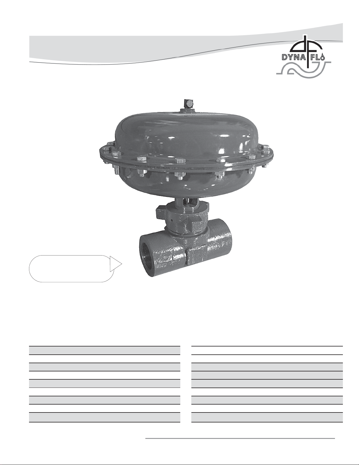
Model DF269 Control Valve
P-269M0117A 6
Operation, Parts, and Instruction Manual
FAIL CLOSED ACTUATOR DISASSEMBLY
(Continued)
16 Remove the hammer nut (Key 30) from over the bonnet,
inspect the threads for damage and corrosion.
17 Remove the washer (Key 18) from the hammer nut seating
surface of the bonnet, inspect the washer for damage or
corrosion and replace if necessary.
18 With the bonnet removal and actuator disassembly
complete, pull the plug and stem assembly (Keys 5 & 3)
out of the bonnet (Key 2).
19 Remove the cage bushing (Key 20), spring washers
(Key 12), packing spacer (Key 31), and packing (Key 11)
from the bonnet bore. Inspect all parts for damage and
corrosion. Retain the cage bushing, spring washers, and
spacer for use in the reassembly of the valve.
20 Using a mechanics pick-set, remove the stem bushing
(Key 13) and remove the o-ring (Key 6) from the bonnet.
Be careful not to scratch or damage o-ring surfaces.
21 With all the parts removed from the bonnet, clean and
inspect all gasket and packing sealing surfaces. Check
threads for damage.
NOTE
For standard valve trim, the cage and seat ring are
one piece. A two piece cage and seat ring design is
used for optional trim materials but are sold together
as one unit.
22 With the bonnet/body separated, remove the cage / seat
ring (Key 4) assembly from the valve body. There is a
small hole at the top of the cage, remove the cage/seat
ring using a pick set through the removal hole. Avoid
removing the cage using the cage windows.
23 Wipe the seat ring surface of the body and inspect for signs
of leakage, corrosion, or other marks.
24 Using a mechanics pick set, remove the o-ring (Key 10) on
the side of the seat ring. Inspect the o-ring groove for
corrosion or damage and replace the o-ring.
25 Inspect all sealing and guiding surfaces for damage.
Seating surfaces can be re-machined or re-lapped if
required.
26 Inspect the inside machined surfaces of the body for
damage or corrosion. Replace or repair the body if
necessary.
FAIL OPEN ACTUATOR DISASSEMBLY
All Key references to follow are from Figures 2 & 4.
1Vent the pneumatic actuator loading pressure if pressure is
still present from bonnet / body disassembly.
2 Begin by removing the 10 short (1”) cap screws (Key 26)
from the actuator casings (Key 16 & 17) using two 9/16”
wrenches or an impact wrench with a 9/16” socket. Be sure
to leave the 2 long cap screws.
CAUTION
The springs inside the actuator casings are still under
compression. It is necessary to take proper safety
precautions and to follow proper procedures.
3Once the 10 short cap screws have been completely
removed, begin loosening the two long (1-1/4”) cap screws
in an alternating pattern. During removal, try to keep the
upper casing (Key 16) level until the springs are no longer
under compression, then completely remove the long cap
screws and upper casing.
4 A 5/8” wrench is required to remove the stem nut
(Key 29).
5Remove the diaphragm plate washer (Key 23).
6Remove the diaphragm (Key 14) and inspect surface for
wear, stretching and tears. Replace if necessary.
7Remove the diaphragm plate (Key 24). Inspect the
diaphragm plate for corrosion and damage.
8Remove the diaphragm plate spacer (Key 25) and inspect the
spacer for damage.
9Remove the actuator springs (Key 15) from the diaphragm
plate (Key 24).
10 To replace o-ring under lower casing use a 1-1/2” deep
socket or wrench to remove the bonnet lock nut (Key 22).
11 Remove the flat washer (Key 21) and lower diaphragm
casing (Key 17). Take note of the position of the lower
casing for reassembly purposes.
12 Remove the casing o-ring (Key 7) and replace.