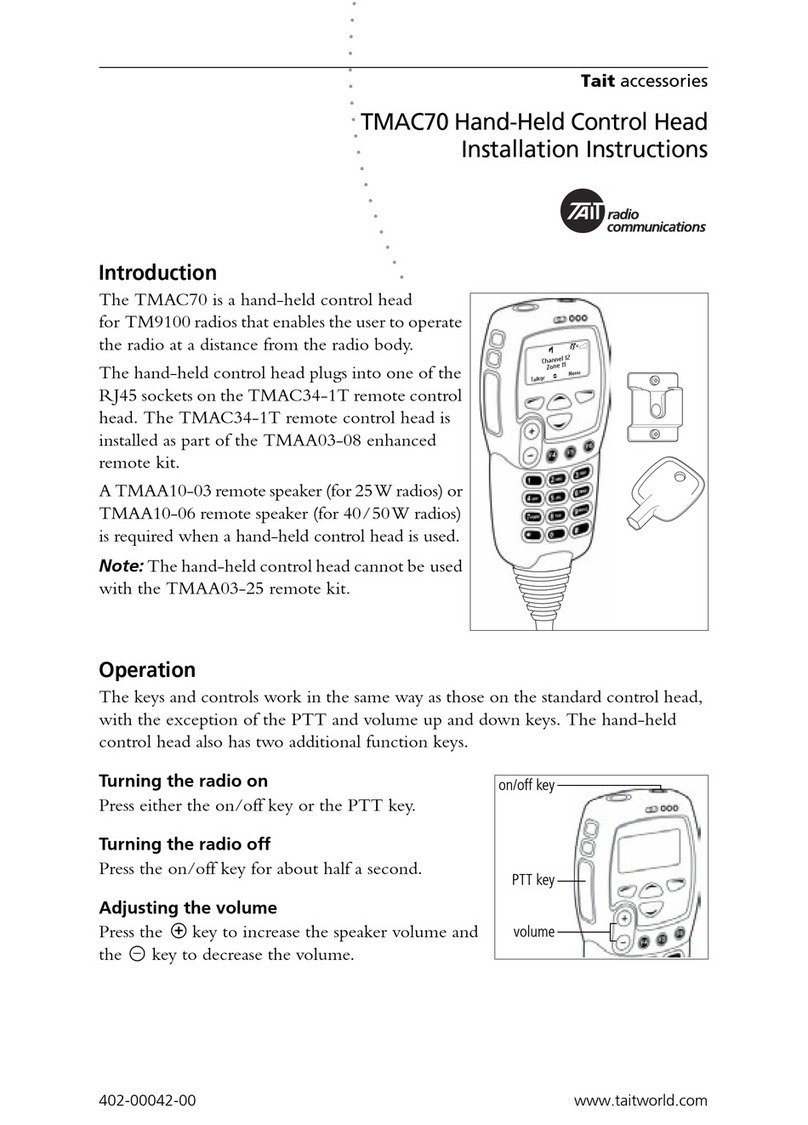
SEA GATE 2 User manual

GATE 2
CONTROL UNIT
67410191
International registered trademark n. 2.777.971

SAFETY INSTRUCTIONS ..........................................................................................................................3
PARTS SPECIFICATIONS..........................................................................................................................5
CONNECTIONS..........................................................................................................................................6
SLOW-DOWN MODE, DIP SWITCHES LOGIC PROGRAM......................................................................7
OPERATING TORQUE ADJUSTMENT ......................................................................................................9
BRAKE (SLOW DOWN) LENGTH ADJUSTMENT .....................................................................................9
PAUSE LENGTH ADJUSTMENT................................................................................................................9
LEDS...........................................................................................................................................................9
RADIO RECEIVER, START BUTTON CONNECTIONS...........................................................................10
PHOTOCELLS, BUZZER CONNECTIONS ..............................................................................................11
ELECTRIC LOCK, MAGNETIC LOCK, SOLENOID LOCK CONNECTIONS...........................................12
SAFETY EDGE, FLASHING LAMP, COURTESY LIGHT, TIMER CONNECTIONS .................................13
POWER SUPPLY, MOTORS, CAPACITORS CONNECTIONS FOR HYDRAULIC OPERATORS ..........14
POWER SUPPLY, MOTORS, CAPACITORS CONNECTIONS FOR ALPHA OPERATORS ...................15
ANTENNA, SAFETY GATE, STOP BUTTON CONNECTIONS................................................................16
SELF-LEARNING OF OPERATING TIME FOR SWING GATES OPERATORS ......................................17
PROGRAMMING A TRANSMITTER ON START......................................................................................20
PROGRAMMING A TRANSMITTER ON PARTIAL START ......................................................................20
LOOP DETECTOR WIRING .....................................................................................................................21
TROUBLESHOOTING ..............................................................................................................................23
SALES CONDITIONS AND WARRANTY .................................................................................................24
GATE 2
TABLE OF CONTENTS
2
International registered trademark n. 2.777.971
REV 05 - 10/2010

GATE 2
WARNING: Not following these instructions may
cause severe injury or death to person
END USER ISTRUCTIONS
IMPORTANT SAFETY INSTRUCTIONS
WARNING - To reduce risk of severe injury or death:
1) READ AND FOLLOW ALL INSTRUCTIONS
2) Never let children operate or play with door controls. Keep the remote control away
from children.
3) Always keep the moving system in sight and away from people and objects until it is
completely closedor stopped. NO ONE SHOULD CROSS THE PATH OF THE
MOVING SYSTEM.
4) Test the system gate operator monthly. The system MUST reverse on contact with a
rigid object or when an object activates the non-contact sensors. To obtain a reverse on
contact with an object on hydraulic linear and in-ground operators SEA recommend to
install the patented safety device “SAFETY GATE” for each leaf.
After adjusting the force or the limit of the travel, retest the gate operator. Failure to
adjust properly the gate operator properly can increases the risk of severe injury or
death.
5) Use the manual release only when gate is not moving
6) KEEP GATES PROPERLY BALANCED AND MAINTAINED. An improper balancing
or maintenance increases the risk of severe injury or death. Have a qualified service
personal to make repairs to cables, spring assemblies and other hardware.
7)The entrance with a gate operators system is for vehicles only. Pedestrian MUST use
separate entrance.
8) Every gate operator installation MUST have secondary protection devices against
entrapment, such as edge sensors and photo beams more in particularly in places
where the risk of entrapment is more likely to occure.
SAVE THESE INSTRUCTIONS
The installer is responsible for grounding the operator system,
for providing the main power breaker switch, and for making sure
that the entire gate systems meets all applicable electrical codes.
3
International registered trademark n. 2.777.971
REV 05 - 10/2010

GATE 2
GROUNDING
Good grounding and proper surge suppression are an integral part of proper installation for
a gate operator system. One or all of the following may require surge suppressors: high
voltage power lines, low voltage power lines, telephone lines, data lines, low voltage control
lines and loops. How much surge suppression is required depends upon how susceptible
the area is to lightning and power surges. Regardless, good grounding is essential. To
realize maximum protection, proper grounding and proper surge suppression is absolutely
necessary.
If the circuit breaker box is located close to the gate operator system, for example, in a
guard house, then the ground from that circuit can be used to ground the gate operator
system. Eliminate all 90° bends in ground wires and keep a minimum of three feet between
the surge suppressor and the equipment being protected.
If the power source or circuit breaker box is not located close to the gate operator system an
Isolated Ground Zone (IGZ) needs to be created. An IGZ can also be created if the circuit
breaker box is located close by the gate operator system. An IGZ is an imaginary circle
drawn around the gate operator system. The gate operator system not only includes the
gate operators and control panel, but all of the accessories and devices associated with it at
that controlled entry point. This includes loop detectors, card readers, digital entries,
telephone entries, any device that has a ground or requires a ground and ali of the surge
suppressors. The ground bus is a common ground point calied a Single Point Ground
(SPG). It is used to bond all the equipment and device grounds in the IGZ together. The
SPG is very important because it helps eliminate different ground potentials that can be
present on the equipment. In such cases, equipment damage occurs even with surge
suppressors.
Do not use or connect the ground wire coming from the circuit breaker box. By using an
Isolated Ground Zone, you are separating the gate operator system from the house or
building ground. This eliminates ground potentials. It is recommended that the ground bus
be located in a separate NEMA type enclosure. All grounds will be tied to this ground bus.
Some points to remember:
Keep all ground wires as straight as possible. Do not have any sharp 90° bends. Have a
minimum of 3 feet of wire between the surge suppressor and the equipment being
protected.
Equipment ground wire should be a minimum of 12 AWG. The main ground wire from the
bus bar to the ground rod shouid be an 8 or 6 AWG copper wire. Ground rod should be a
minimum of 10 feet in length, longer depending on local soil conditions.
For more information regarding good grounding practices check: National Electric Code
art. 250; IEEE Emerald Book, standard 100; International Association of Electric
Inspectors.
IMPORTANT SAFETY INSTRUCTIONS
SAVE THESE INSTRUCTIONS
READ AND FOLLOW ALL INSTRUCTIONS
4
International registered trademark n. 2.777.971
REV 05 - 10/2010

CN3CN2
RL1 RL2
RL3
F1
F2
P1
P2
Rv1
Rv2
Rv3
CN1
U1
U2 DIP
J1
LED5
LED6
LED7
LED8
LED9
LED10
LED11
LED1
LED2
LED3
LED4
LED12
LED13
LED14
LED15
LED16
CMR
LEDPLEDP
CNP CN4
GATE 2
5
PARTS SPECIFICATION
LED1 = Auxiliary input
LED2 = Partial Start
LED3 = Start
LED4 = Limit switch in closing Motor 2
LED5 = Limit switch in opening Motor 2
LED6 = Limit switch in closing Motor 1
LED7 = Limit switch in opening Motor 1
LED8 = Photocell 2
LED9 = Photocell 1
LED10 = 24V Auxiliary output
LED11 = Tx Photocell output
LED12 = Troubleshooting LED
LED13 = Electric Lock
LED14 = Encoder (reversing sensor) 2
LED15 = Encoder (reversing sensor) 1
LED16 = Stop
LEDP = Programming
CN1 = 24V input / output connector
CN2 = 24V input / output connector (green)
CN3 = Motors and Power supply connector (orange)
CN4 = 24Vac Photosync connector
Rv1 = Motor torque adjustment
Rv2 = Brake length adjustment (slow down length)
Rv3 = Pause time adjustment
P1 = Operating time memory button
P2 = Programming transmitters button
DIP = Dip-switch Function Setting
F1 = Output and motor fuse (6.3AT)
F2 = Accessories fuse (2A)
J1 = Slow-down adjustment
RL1 = Motor Power Supply Relay
RL2 = Motor Operating Direction Relay
RL3 = Garden Light Relay
U1 = Micro-controller
U2 = EEPROM memory
CNP = PALM connector
CMR = Receiver module connector
International registered trademark n. 2.777.971
REV 05 - 10/2010
GREEN ORANGE

CN2
1 2 3 4 5 6 7 8 9 10 1112 13 14 15
m24V Trans itter
photocell
24VcAuxili y
d ar
e
Photoc l 2
l
n n(ope i g)
t
Limi switch
l o or
c osingM t 2
tw
Limi sitch
g o or
openin Mt2
START
xi i y ntAular i pu
C mmono
16 17
iartal START
P
mit sw thLi ic
clingMo or
os t1
mitsw tchLi i
eningMo or
op t 1
Photocel 1
l
(c o i g)
lsn
ck 1VLo2
mm
Coon
C mmo
o n
CN3
M2
~
Opening
Closing
mCom on
a M2
Cap citor
t
Cour esy light
115V
Neutral
haseP
oundGr
1 2 3 4 5 6 7 8 9 10 1112 13 14 15 16 17
Capacito M1
r
M1
~
Opening
Closing
mCom on
lasher
F
115V
Operating logics
Auxiliary input configuration
Pre-flashing
Automatic closing
Photocell autotest
Reversing sensor (Safety Gate)
Soft start
Brake (slow-down)
Leaf locking
Reverse stroke
1122334455667788991010 1111 1212
ONON
ON= Function Active
DIP
Leaf delay in opening and closing
GATE 2
CONNECTIONS
6
CN1
AEIL
R A
R
eesn
vrig
sno
esr2
STOP
1 2 3 4 5 6
een
Rvrs
ig
snoesr
1
Re . se r
v nso
po r sup ly
we p
ee n
Rvr
s
ig
sno
esr
Gr en
e
r
B own
Whte
i
eW h t i
International registered trademark n. 2.777.971
CN4
1122
24V~
Note: For
the power
supply of the
synchronized
photocells.
ATTENTION NOTE: In the configuration of the swing gate double leaf the limit switches must not be bridged.
REV 05 - 10/2010
(Green)
(Orange)
24V
4
0m a
0 Amx
24
uzzerV
B

WORKING LOGICS
Four different working logics can be selected.
The programming takes place using DIP1 and DIP2.
- MANUAL LOGIC
ASTART command opens the gate. Asecond START while it is opening stops the motor.
A START command while it is closing stops the motor.
Important note: For the automatic re-closure, set DIP 6 on ON
- SAFETY LOGIC
ASTART command opens the gate. Asecond START while it is opening reverses the motor.
ASTART command while it is closing reverses the motor.
Important note: For the automatic re-closure, set DIP 6 on ON
- AUTOMATIC LOGIC 1
A START command opens the gate. A second START while it is opening is not accepted. A START while it is closing
reverses the direction.
P. N.: for automatic closing, set DIP SWITCH 6 to the ON position.
Important note: For automatic closing, set DIP SWITCH 6 to the ON position.
Important note: If Dip 6 of the automatic closing is not activated the start in pause will be accepted.
- AUTOMATIC LOGIC 2
ASTART command opens the gate. Asecond START while it is opening is not accepted. ASTART during the pause time closes the
gate immediately. A START while it is closing reverses the direction.
P. N.: for automatic closing, set DIP SWITCH 6 to the ON position.
P. N.: For automatic closing, set DIP SWITCH 6 to the ON position.
OPENED
CLOSED
OFF / OFF
ON / OFF
DIP1 AND DIP2 PROGRAMMING FOR THE SELECTION OF THE WORKING LOGIC
If Dip1 and Dip2 are programmed in this way, the control unit will work with Manual Logic
If Dip1 and Dip2 are programmed in this way, the control unit will work with Safety Logic
DIP
1 / 2
1 / 2
OFF / ON
ON / ON
If Dip1 and Dip2 are programmed in this way, the control unit will work with Automatic 1 Logic
If Dip1 and Dip2 are programmed in this way, the control unit will work with Automatic 2 Logic
1 / 2
1 / 2
GATE 2
DIP
1 2 3 4 5 6 7 8 9
ON
DIP
10 11 12
SLOW-DOWN MODE, DIP SWITCHES,
LOGIC PROGRAM
J1
J1
Slow-down mode
(only DIP 10 ON)
1
2
Choose the slow down
modality which can be
more appropriate for
the installation.
1: Jumper unconnected
2: Jumper connected
7
International registered trademark n. 2.777.971
REV 05 - 10/2010

LEAF DELAY IN OPENING AND CLOSING
Activating this function, the Leaf Delay in opening and closing will be eliminated. Both leaves will
work simultaneously. It is advised to activate this function on single leaf applications and/or in
applications where the Delay is not required.
4
OPENED
CLOSED
OFF
ON
DIP 3 AND DIP 4 PROGRAMMING FOR AUXILIARY INPUT CONFIGURATION
SAFETY EDGE ( N.C. contact)
When the Safety Edge Contact opens, the gate reverses direction and stops after about 1 second. A
START command is required to restart movement
TIMER (N.O. contact)
If a TIMER is connected to this input the gate can be opened and kept open as long as the contact
remains closed. Using a 24-hour or 7-day timer allows gate opening times to be scheduled as
required. When the TIMER contact is open the automatic operation functions according to pre-set
logics.
DIP
3
3
ON
ON
ON
PROGRAMMING OF OTHER DIPS FOR OTHER FUNCTIONS
PRE-FLASHING
When this function is activated the flashing lamp and warning light begin flashing about 3 seconds
before the motor starts, both when closing and opening.
AUTOMATIC CLOSING
Activating this function causes the gate to close automatically, after the time set by the trimmer Rv3.
This function can be activated independently of the operating logic set (DIP SWITCH 1 and 2).
DIP
5
6
ON
ON
PHOTOCELLAUTOTEST
When this function is activated a test is carried out on the photocells before any gate movement
takes place. To enable this function the photocell transmitter must be connected to terminals 13
(24V) and 17 (Negative) of connector CN2.
The flashing lamp and troubleshooting LED will both flash slowly if a malfunction occurs.
7
8
ON
“SOFT” START
When this function is activated, the motor will start at a lower torque to avoid stresses and strains on
the gate's mechanical components. The starting torque is a percentage of the normal operating
torque.
P.N.: It is not advised to operate this function when the gate is very heavy or does not run smoothly.
9
OPENED
CLOSED
ON
12
REVERSING STROKE
This function (to use exclusively on swing gates) is used to facilitate the electric lock release. Before
beginning the opening cycle, as soon as the start order is given, the leaves are supplied for about 1
sec. in closing.
GATE 2
DIP SWITCHES, LOGIC PROGRAM
ON
BRAKING (slow-down) AT LIMIT SWITCH
When this function is activated motor speed reduces slowly before the limit switch is reached or
before the end of the operating time. This function is designed to bring the leaf gently up to the stop
position and prevent the gates clashing. The closing speed is fixed, while the slow-down time can be
adjusted using the trimmer Rv2.
It is necessary to activate this function to choose the slow-down modality through jumper J1.
Remember to set this DIP in Off position in case of mechanical or hydraulic brake.
10
ON
LEAF LOCKING
When this function is activated, at the end of the slow-down phase, and when the leaf is up against
the mechanical stop, the motor is supplied at maximum power for about 1 second. This increases
the oil pressure in the motor and makes the hydraulic lock more effective.
P.N.: this function SHOULD NOT be activated when used on sliding gates since it could
cause over-running of the limit switches and the automation system to jam.
Note2: With the Palm through the function PushOpen it is possible to exclude the tightening
of the leaf during the opening phase.
11
8
International registered trademark n. 2.777.971
!!
ENCODER MANAGEMENT (reversing sensor)
The signals sent from an encoder located on the motor or gate are managed when this function is activated.
This results in any obstacles found in the gate's path being detected and reverses the gate direction of
movement for one second, it stops and waits for commands. The flashing lamp and troubleshooting LED will
both flash slowly if a malfunction occurs. With a following start the automation will proceed in slow down
speed until it reaches the stop. Note:After two consecutive obstacles the BUZZER will be activated.
P.N.: If an encoder is not fitted, set the DIP SWITCH to OFF.
Note: The Encoder sensibility can be adjusted through the PALM or through the pushbuttons Ptime
and Pcode on board of the control unit.
REV 05 - 10/2010

LED1 (AUX INPUT)
LED2 (PARTIAL START)
It must be usually switched off and it must switch on when an partial opening control is given.
LED3 (START)
It must be usually switched off and it must switch on when an opening control is given.
LED4 and LED5 (CLOSING LIMIT SWITCH MOTOR 2) / (OPENING LIMIT SWITCH MOTOR 2)
LED6 and LED7 (CLOSING LIMIT SWITCH MOTOR 1) / (OPENING LIMIT SWITCH MOTOR 1)
They must be usually switched on and they must switch off when the limit switches are started up.
LED8 and LED9 (PHOTOCELL 2) and (PHOTOCELL 1)
It must be usually switched on and it must switch off when the photocell is darkened.
LED10 (24V AUX POWER SUPPLY)
LED11 (TX PHOTOCELL POWER SUPPLY)
LED12 (TROUBLESHOOTING LED)
If the automation stops to work, the Troubleshooting LED will indicate which safety caused the event through many different flashing spaced
out by a second pause.
1 flash = PHOTOCELLS
2 flashes = SAFETY EDGE
3 flashes = ENCODER (reversing sensor)
4 flashes = STOP
5 flashes = PHOTOCELLSELF-TESTING
6 flashes = TRIAC TEST
The flashing sequence will be repeated even on the flashing lamp for 15 seconds.
LED13 (ELECTRIC LOCK)
LED14 and LED15 (ENCODER2) and (ENCODER 1)
LED16 (STOP)
It must be usually switched on and it must switch off when a STOP control is given.
LEDP (Programming)
Rv1
Rv2
Rv3
OPERATING TORQUE ADJUSTMENT
This trimmer is used to adjust the motor torque. This
adjustment is essential for operators without
mechanical or hydraulic anti-crush devices and must
be carried out so that there is no risk of people or
objects being crushed. It must always be executed in
accordance with current legislation on the subject.
BRAKE (slow-down) LENGTH
ADJUSTMENT
This trimmer is used to adjust the length of the slow-
down.
PAUSE LENGTH ADJUSTMENT
This trimmer allows the PAUSE time to be adjusted
between 0 and 120 seconds.
Set DIP SWITCH 6 to the ON position to enable
automatic closing.
P.N.: TURNING THE TRIMMERS CLOCKWISE
INCREASES THE TIMES/VALUES
+
-
GATE 2
TRIMMER REGULATION, LEDS
Rv1
Rv2
Rv3
+-
+-
+-
LED1
LED2
LED3
LED4
LED5
LED6
LED7
LED8
LED9
LED10
LED11
LED12
LED13
LED14
LED15
LED16
9
International registered trademark n. 2.777.971
Number of lightning
1
2
3
The sequence of lightning, intervals of pause, are shown on the flashlight (for ca. 20 sec.) and on the control lamp (until a new START).
ALARM INDICATION BOARD ON CONTROL UNITS GATE
Number of lightning
4
5
6
Type of alarm
Stop
Photocell self-testing
Triac test
Type of alarm
Photocell
Safety edge
Encoder
REV 05 - 10/2010

10 11 12 13 14 15 16 17
1 2 3 4 5 6 7 8 9
Start Button
An impulse given to this entrance commands
the opening/closing of the automation. It can
be given by a key switch, a loop detector, a
keypad, etc.
To connect the supplied devices (for ex. Loop
detector) see the related instructions.
-+
C
Partial Start
To obtain a partial opening (7 second gate opening) connect the
key-button wires as in the picture. It is possible to connect other
command devices (push button board, radio receiver, keypad).
Note1: the contact for the partial opening is a N.O. Contac
(Normally opened)
Note2: the partial opening will be always executed on the M1 motor.
Com
GATE 2
RADIO RECEIVER, START BUTTON
CONNECTIONS
1
1
4
15
1
3
1
4
1
4
CN2
10
International registered trademark n. 2.777.971
REV 05 - 10/2010
Connection of a radio receiver
This connection allows to command the total
opening/closing of the automation. For the
receiver connection make reference to the
related instruction manual.
+ = 24V ,
- = 0V ,
C = Contact
Com = Common

10 11 12 13 14 15 16 17
1 2 3 4 5 6 7 8 9
CN2
-+
Photocell
self-testing
+C C
+
-
Com
N.C.
RX
TX
+
-
Com
N.C.
RX
TX
IMPORTANT: UL325 standards requires an audible alarm to go OFF after 2 consecutive events
detected by the primary entrapment protection of the gate operator (for ex. reversing sensor).
!
GATE 2
PHOTOCELLS, BUZZER, CONNECTIONS
17
14
15 17
15 17
9
10
11
International registered trademark n. 2.777.971
REV 05 - 10/2010
Buzzer (24Vdc) Audible Alarm
Use a buzzer 24V of 100 dB. The buzzer will be switched on
after two consecutive activations of the anticrush sensor. To
reset the allarm it is necessary to push the button STOP. Anyway
after 5 minuts the buzzer will stop to sound and the automation
stands still waiting for commands.
Photocells 2 Connection
When the photocells beam is crossed, the automation
reverses its movement if in closing phase. In opening
it causes the stop of the gate until it is occupied, when
released the gate returns into open postion.
Note: When not used make a jumper between
contact 9 and the common.
Note : With the PALM device it is possible to set as
PHOTOSTOP, that means that it does not allow to
the gate to open, while it does not intervene
during the remaining opening.
+ = 24V - = 0V C = Contact
Com = Common
Photocells 1 Connection
When the photocells beam is crossed, the automation
reverses its movement if in closing phase.
To use the photocells self- testing connect the (+) of the
TX photocell 1 with contact 13 instead of 15.
Note: When not used make a jumper between contact
10 and the common.
Note: With the PALM device it is possible to set this
photocell as PHOTOCLOSE, that means, that if
occupied during the pause, the automation
interrupts the same and recloses immediately.
+ = 24V - = 0V C = Contact Com = Common

10 11 12 13 14 15 16 17
1 2 3 4 5 6 7 8 9
CN2
-
GATE 2
ELECTRIC LOCK, MAGNETIC LOCK
SOLENOID LOCK CONNECTIONS
16
1
1 2 3 4 5 6 7
-
Magnetic Lock wiring
16
17
Magnetic Lock
Power for
Magnetic Lock
N.C.
1 2 3 4 5 6 7
Solenoid Lock wiring
16
17
Solenoid Lock
Power for
Solenoid Lock
N.O.
The Power Supply is not provided.
The Power Supply is not provided.
optional board
optional board
12
International registered trademark n. 2.777.971
REV 05 - 10/2010
Electric lock exit
An electric lock of 12V or of 24 Vdc 15W
max can be connected .The electric lock
activates at every opening cycle for about
1,5 s.

CN3
10 11 12 13 14 15 16 17
1 2 3 4 5 6 7 8 9
10 11 12 13 14 15 16 17
1 2 3 4 5 6 7 8 9
-
Afurther safety can be obtained making a connection with the safety edge mentioned on the side.
If it is start up, the safety edge reverses the movement of the gate for two seconds and it stops.
To use the safety edge, place dip-switches 3 on OFF.
Notice: if the safety input is not used, make a Jumper between 1 and 2 .
Safety edge input
Timer
Flashing Lamp (115V)
The flashing lamp is an important accessory which warns the
gate operating.
To connect it, connect the wires of the flashing lamp as in the
picture.
It is possible to activate a pre-flashing of 3 seconds before
activating the automation placing Dip 5 on ON.
Notice: The warning lamp gives the same warning signals
as the LED 12 described in pag. 9
Courtesy Light (115V max 100W)
During the working phase, courtesy light stays switched on.
Note: With the Palm it is possible to modify this time from
15 to 240 s.
GATE 2
SAFETY EDGE, FLASHING LAMP, COURTESY
LIGHT, TIMER CONNECTIONS
1
2
12
12
11
13 14
CN2
13
International registered trademark n. 2.777.971
With DIP3 on ON it is
possible to connect a
timer. The Timer
executes the timed
opening and keeps the
gate open for the
whole adjusted time.
REV 05 - 10/2010

CN3
10 11 12 13 14 15 16 17
1 2 3 4 5 6 7 8 9
Example
Motor 1
Output for Motor 1 connection
M = OPEN/CLOSED
Com = COMMON
Motor 2
Output for Motor 2 connection
M = OPEN/CLOSED
Com = COMMON
M1
M2
Capacitor 1
Capacitor 2
Com
PGN
Example
Power input
Input for the connection of the electric power.
P = PHASE
N = NEUTRAL
G = GROUND NOTICE: for the connection to the
electric power see the law in force.
M M
GATE 2
HYDRAULIC MOTORS, POWER SUPPLY,
CAPACITORS CONNECTIONS
2
1
7
634516
8
9
10
16
16 1715
Com
M M
14
White
White
Black
Black
Green
Green
Violet
Violet
International registered trademark n. 2.777.971
REV 05 - 10/2010

CN3
10 11 12 13 14 15 16 17
1 2 3 4 5 6 7 8 9
GATE 2
MOTORS, CAPACITORS, POWER SUPPLY
CONNECTIONS for ALPHA
15
Motor 1
Output for Motor 1 connection
M = OPEN/CLOSED
Com = COMMON
Motor 2
Output for Motor 2 connection
M = OPEN/CLOSED
Com = COMMON
M1
M2
Capacitor 1
Capacitor 2
ALPHA
ALPHA
Power input
Input for the connection of the electric power.
P = PHASE
N = NEUTRAL
G = GROUND NOTICE: for the connection to the
electric power see the law in force.
4
5
5
4
1 12 23 3
Com
GNM M
Com
M M P
16 1715
International registered trademark n. 2.777.971
REV 05 - 10/2010

CN1
1 2 3 4 5 6
-+
SAFETY GATE
SAFETY GATE
1
2
234
23
5
2
6
CN4
P1
P2
LEDP
ANTENNA, SAFETY GATE, STOP BUTTON
CONNECTIONS
White
Brown
Green
White
Antenna
Connect the
antenna as in the
picture.
Stop Button
The pressure of this button stops immediately the motors in any
condition /position. With the following start impulse the gate will always
go in closure.
Note: if it is not used, make a jumper between terminals n° 2 and 6.
Encoder adjustment procedure on board of the control unit
1. Keep pressed both Ptime and Pcode buttons for 3 seconds until ledP turns on..
2. The led turns on and stays on for 1 second, afterwards it reproduces the number of
flashes corresponding to the level of the set encoder sensibility (from 1 to 15, where 15
stands for the maximum insensibility)
3. If the set level is not suitable, press the push-button Pcode to increase or Ptime to
decrease it. Every impulse corresponds to the increase or the decrease of one unity.
4. After 1 second from the last pressure of the push-button the set sensibility level will be
shown through the corrisponding number of flashes.
5. After 3 seconds from the visualization, the procedure will be left and the ledP
switches off.
Note: Execute the adjustment with still- standing gate.
International registered trademark n. 2.777.971
GATE 2
Encoder (reversing sensor) on motor 2 (DIP8
ON)
The encoder or Safety Gate is a system which
detects any obstacle during the operating of the
gate.
When activated the motor reverses for 1 sec. It is
set in the factory on a middle level but can be
modified. Low sensibility levels do not allow a fast
inversion as required by the En12453 rules.
Note: After two consecutive inversions the
BUZZER will be activated.
Encoder (reversing sensor) on motor 1 (DIP8
ON)
The encoder or Safety Gate is a system which
detects any obstacle during the running of the
gate.When activated the motor reverses for 1 sec.
Note: With the PALM device or through the
pushbuttons Ptime and Pcode on board of the
control unit. it is possible to adjust the
sensibility of the encoder on a scale from 0 to
15, where 0 indicates the max. sensibility
during the inversion.
Note: Every time when there is no current
supply and after every osbstacle the
automation, when no limit switches are
installed, will proceed slowly until it reaches
the stop.
16 REV 05 - 10/2010

STEP 1 (Note: On swing gates with two leaves the limit switches have not to be bridged)
Make all the electrical connections and jumpers on all the unused N.C. contacts (photocells, limit switches,
etc).
If a geared motor equipped with a mechanical or hydraulic anti-crush safety device is being used, set the
operating torque (trimmer Rv1) to the maximum value and then adjust the motor torque using the special by-
pass valves or clutch adjustment screws located on the actuators.
If a motor without a mechanical or hydraulic anti-crush safety system is being used, set the operating torque
to the maximum value ONLY for the self-learning process. Immediately afterwards, set a torque value that
will ensure anti-crush safety, in accordance with current legislation.
ATTENTION!
THIS PROCEDURE IS POTENTIALLY DANGEROUS AND MUST BE CARRIED OUT ONLY BY
SPECIALIZED PERSONNEL, ADOPTING ALL SAFETY PRECAUTIONS.
STEP 2
Disconnect the power supply (Fig. 1), release the gate operator (Fig. 2) and stop the leaves in the half-open
position (Fig. 3). Lock the motor (Fig. 4) and turn ON the power (Fig. 5).
Fig. 2
Unlock
Fig. 1
Fig. 3
M1
Fig. 4
M2
FF
O
Fig. 5
NO
2
1
GATE 2
SELF-LEARNING OF OPERATING TIMES
FOR SWING GATES OPERATORS
17
Lock
Example
Example
International registered trademark n. 2.777.971
Notice: Encoder activation
With the safety gate (encoder 1 and encoder
2) on both motors put dip 8 on ON before
programming.
To exclude its function put dip 8 on OFF
avoiding to repeat the selflearning
procedure.
REV 05 - 10/2010

STEP 3
(from STEP 2) When the leaf reaches the closing mechanical stop, press button P1 (Fig. 6).
Motor M1 will also start a closing cycle.
When the gate reaches the closing mechanical stop, press P1 again (Fig. 7). Do not execute this operation if limit
switches are installed.
Note: If the safety gate is installed you must give the impulse exactly on the stop.
3
The leaf stops and M1 starts an opening cycle.
After a few seconds press P1 once more to set the Leaf Delay in Opening. (The number of seconds waited will result in the
delay of the leaf in opening) NOT TO DO IF DIP 4 IN “ON” POSITION.
When the leaf reaches the opening mechanical stop, press P1 again (Fig. 8). Do not execute this operation if limit switches
are installed. Motor M2 will also start an opening cycle. When it reaches the opening mechanical stop, press P1 again (Fig.
9). Do not execute this operation if limit switches are installed.
Press and Hold button P1 (LED P will come ON)
until motor M2 will start to close the gate*.
Release P1.
P1
LEDP
P1 M2M1 P1
If the motor start to open the gate, take OFF the power and reverse the motor phases.
Make the same type of connection on motor M1 as well.
Repeat the programming procedures (STEP 2).
*
Fig. 6
P1 P1
M2M1
Fig. 7
M2M1
Fig. 8
P1 P1
M2M1
Fig. 9
M2M1
GATE 2
SELF-LEARNING OF OPERATING TIMES
FOR SWING GATES OPERATORS
18
International registered trademark n. 2.777.971
U1U1
U2U2
RV1RV1
RV2RV2
RV3RV3 P1P1
P2P2
F1F1
F2F2
CN1CN1
CN2CN2 CN3CN3
RL1
RL1
2L
R2L
R
R3
L
R3
L
ED1
LED1
L
LE 2D
LE 2D
LE3
D
LE3
D
LE 4D
LE 4D
5LED5LED
L6
E
D
L6
E
D
DL E 7 DL E 7
LE8
D
LE8
D
LED9
LED9
LED10
LED10
1L E1 D1L E1 D
L12
ED
L12
ED
ED
L 13
ED
L 13
LE14
D
LE14
D
E
LD15
E
LD15
D
LE 16
D
LE 16
DIPDIP T1T1
CN4CN4
DL E P DL E P
REV 05 - 10/2010

Motor M2 will start a closing cycle automatically.
After a few seconds press P1 once more to set the Leaf Delay in closing. (The number of seconds waited will result in
the delay of the leaf in closing) NOT TO DO IF DIP 4 IN “ON” POSITION
When the leaf reaches the closing mechanical stop, press P1 again (Fig. 10). Do not execute this operation if limit
switches are installed.
At this point motor M1 will start a closing cycle.
When the closing mechanical stop is reached, press P1 again (Fig. 11). Do not execute this operation if limit switches are
installed.
When motor M1 reaches the closing mechanical Stop, press P1 for the last time.
Programming is completed.
Check that the times are saved properly by giving a START command or pressing button P1.
If necessary repeat the learning procedure from stage 2.
P1 P1
Fig. 10
M2M1 M2
M1
Fig. 11
STEP 4
If used with a motor without a mechanical or hydraulic anti-crush safety device, adjust trimmer Rv1 to values that will
ensure anti-crush safety, in accordance with current legislation.
If, after adjusting the operating torque, the operating time is insufficient (e.g. the leaf fails to open or close completely),
repeat STEP 2 with the motor torque value set for the normal use of the system.
Adjust the slow-'down length (if enabled), using trimmer Rv2.
4
GATE 2
SELF-LEARNING OF OPERATING TIMES
FOR SWING GATES OPERATORS
19
PALM FUNCTIONS:
International registered trademark n. 2.777.971
GATE 1-GATE 2 Administration
• Visualisation and modification of the following parameters:
• Working times
• Leaf delay
• Partial opening time
• 2 n. maintenance cycles adjustment
• Antisqueezing sensibility SAFETY GATE
• PhotoStop
• PhotoClose
• PushOpen (excludes the pushover during opening phase)
CN3CN2
RL1 RL2
CN4
RL3
F1
F2
P1
P2
Rv1
Rv2
Rv3
CN1
U1
U2 DIP
J1
LED5
LED6
LED7
LED8
LED9
LED10
LED11
LED1
LED2
LED3
LED4
LED12
LED13
LED14
LED15
LED16
LEDP
FUNCTION OF THE CONTROL UNIT GATE 2 FOR ONLY ONE MOTOR
The Gate 2 control unit can be used for the movement of one single leaf, when swing leaf it’s without limit switch. To
prepare the control unit for the programming of this function it is sufficient to PUT A JUMPER between the limit switch
contacts of the motor M1 (connected motor) and to exclude the leaf delay (Dip 4 ON). Keep pressed P1 until the motor
starts to close, when it reaches the stop in closing press P1 again, and the motor will open. Press P1 after the stop in
opening has been reached, the motor will start a closing cycle, when it reached the stop in closing press P1 and the
programming is finished.
FUNCTIONING OF THE GATE2 CONTROL UNIT FOR A DOUBLE SLIDING GATE
It is possible to use the GATE2 control unit also to move a double sliding gate with limit switch. To predispose the unit for
the programming of such functioning modality it is sufficient to connect the limit switch connectors of the motors M1 and
M2 and to exclude the leaf delay (Dip 4 on ON )
Press and keep pressed P1 until the motor starts, now the automation continues autonomously with the selflearning of
the times.
REV 05 - 10/2010

GATE 2
PROGRAMMING A TRANSMITTER
WARNING: The default card will only accept ROLLING CODE radio transmitters (Ladbird Roll and and Smart Roll)
associated with the RF ROLL (433 Mhz Code 23120470, 868 Mhz Code 23120480). To program “NOT ROLLING
CODE” transmitters (Smart Dual, Ladybird Dip and Copy and Head) it is necessary to replace the microprocessor
with the appropriate kit (Code 23120419) and to insert on the control unit the RF module (433 Mhz Cod.23120420, 868
Mhz Cod . 23120425).
Note: The RF ROLL receivers will be manageable with the SP40 management software (Code 23105295) and with the
OPEN sytem (Code 23105290).
PROGRAMMING A TRANSMITTER ON START
Press button P2 (PCode) until LEDP turns ON.
If no further code is memorized within 10 seconds, the LED automatically goes OFF and exits the programming procedure.
ATTENTION: If the code entered is already in the memory, it will be deleted. LedP flashes 4 times to confirm this procedure.
PROGRAMMING A TRANSMITTER ON PARTIAL START
1) Press button P2 (PCode) until LEDP turns ON.
2) Press button P1 (PTime). LEDP will start to flash quickly
If no further code is memorized within 10 seconds, the LED automatically goes OFF and exits the programming procedure.
ATTENTION: If the code entered is already in the memory, it will be deleted. LedP flashes 4 times to confirm this procedure.
CANCELLATION OF ALL RADIO TRANSMITTERS
Press and keep pressed button Pcode, ledP will start to flash. Wait until the ledP stops to flash and release the Pcode. LedP
will flash 6 times to confirm the cancellation.
Give a START with the transmitter, using the button chosen for the start
command.
The LED will flash twice to confirm that the transmitter code has been memorized
and will remain ON waiting for further transmitters.
Give a START with the transmitter, using the button chosen for the start
command.
The LED will flash twice to confirm that the transmitter code has been memorized
and will remain ON waiting for further transmitters.
P2
LEDP
P1
LEDP
LEDP
1) 2)
20
International registered trademark n. 2.777.971
P2P2
P2
LEDP
LEDP
U1U1
U2U2
RV1RV1
RV2RV2
RV3RV3 P1P1
P2P2
F1F1
F2F2
CN1CN1
CN2CN2 CN3CN3
RL1
RL1
R2
L
R2
L
RL3
RL3
LD
E1
LD
E1
LED2
LED2
LED3
LED3
EL D 4
EL D 4
LED5
LED5
LD
6
ELD
6
E
7
LED7
LED
EL D8
EL D8
EL 9D
EL 9D
1
LED01
LED0
LED11LED11
L D12
EL D12
E
E1
LD
3
E1
LD
3
L D14
EL D14
E
1
LED 5
1
LED 5
EL D16
EL D16
DIPDIP T1T1
CN4CN4
LDPELDPE
REV 05 - 10/2010
Other manuals for GATE 2
2
Table of contents
Other SEA Control Unit manuals
SEA
SEA GATE 1 DG R1 User manual

SEA
SEA 23001157 User manual
SEA
SEA SWING 2 DG R2F User manual
SEA
SEA USER 1-24V User manual
SEA
SEA USER 1 - 24v DG R1 User manual
SEA
SEA GATE 2 - 24V PLUS User manual
SEA
SEA USER 2 24V DG R1B ALL-IN User manual
SEA
SEA GATE 1 DG R1 User manual
SEA
SEA USER 1 - 24v DG R1 User manual
SEA
SEA GATE 2 DG R1B User manual
SEA
SEA GATE 1 DG R2BF User manual

SEA
SEA GATE 1 DG R2BF User manual

SEA
SEA USER1-24V User manual
SEA
SEA SWING 2 User manual
SEA
SEA USER 2 24V DG ALL IN User manual
SEA
SEA SLIDE NEW MAG User manual

SEA
SEA Orion User manual
SEA
SEA CUBE R. NW User manual

SEA
SEA GATE 1 DG R1 User manual

SEA
SEA USER 1 - 24v DG R1 User manual


