Senix GTS4QL-M2 User manual

8458-9022010-001
4-Cycle 1.9 cu in. (31 cc) Engine
Gasoline Powered Trimmer
Operator’s manual
Model: GTS4QL-M2
For customer support, please call 1-800-261-3981 or send email to:
SAVE THIS MANUAL FOR FUTURE REFERENCE.
2WWW.SENIXTOOLS.COM
TABLE OF CONTENTS
SAFETY..........................................................................................2
KNOW YOUR UNIT........................................................................5
SPECIFICATIONS* ........................................................................5
ASSEMBLY......................................................................................6
OIL AND FUEL................................................................................8
STARTING AND STOPPING...........................................................9
OPERATION..................................................................................11
MAINTENANCE............................................................................13
CLEANING AND STORAGE.........................................................17
TROUBLESHOOTING..................................................................18
PARTS...........................................................................................19
WARRANTY...................................................................................20
Signals an EXTREME hazard.
Failure to obey a safety DANGER symbol WILL result
in serious injury or death to yourself or to others.
Signals a SERIOUS hazard.
Failure to obey a safety WARNING symbol CAN result
in serious injury to yourself or to others.
Signals a MODERATE hazard.
Failure to obey a safety CAUTION symbol MAY result in
property damage or injury to yourself or to others.
CALIFORNIA PROPOSITION 65
This product contains a chemical known to the state
of California to cause cancer, birth defects or other
reproductive harm.
NOTE: Advises you of information or instructions vital to
the operation or maintenance of the equipment.
Read the operator’s manual and follow all warnings
and safety instructions. Failure to do so can result
in serious injury to the operator and/or bystanders.
• SAFETY & INTERNATIONAL SYMBOLS •
Crude oil, gasoline, diesel fuel and other petroleum
products can expose you to chemicals including toluene
and benzene, which are known to the State of California
to cause cancer and birth defects or other reproductive
harm. These exposures can occur in and around oil
elds, reneries, chemical plants, transport and storage
operations such as pipelines, marine terminals, tank
trucks and other facilities and equipment. For more
information go to: www.P65Warnings.ca.gov/petroleum.
This operator’s manual describes safety and
international symbols and pictographs that may appear
on this product. Read the operator’s manual for
complete safety, assembly, operating and maintenance
and repair information.
DANGER:
WARNING:
CAUTION:
WARNING:
WARNING:
SAFETY
SYMBOL NAME MEANING
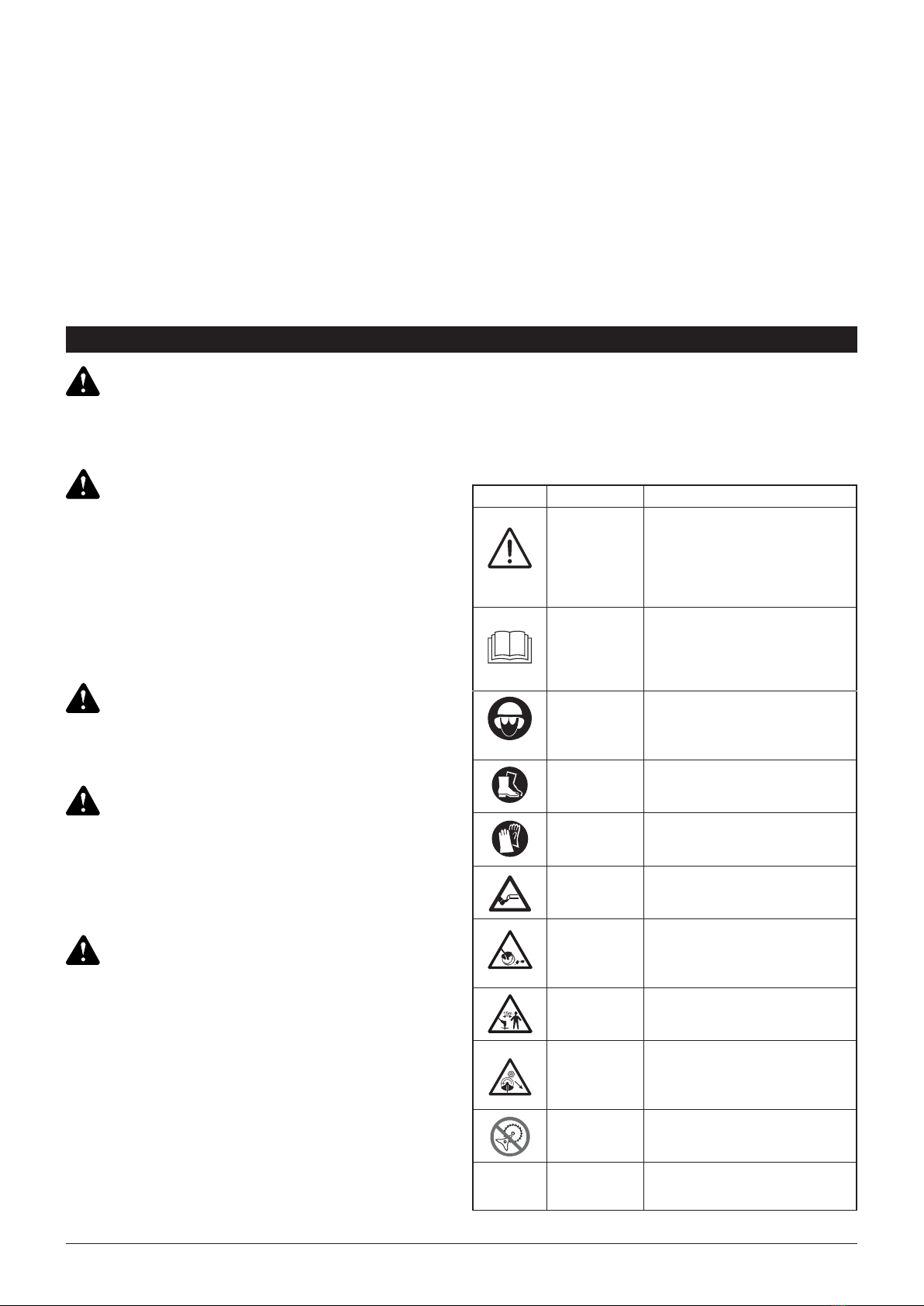
Safety Alert This graphic accompanied
by the words WARNING,
DANGER OR CAUTION calls
attention to an act of a
condition which can
lead to SERIOUS INJURY.
Read
Operator’s
Manual
Read the operator’s manual(s)
and follow all warnings and
safety instructions. Failure to do
so can result in serious injury to
the operator and/or bystanders.
Wear eye
and hearing
protection
Always wear eye protection,
ear protection and head
protection meeting ANSI Z87.1
standards.
Wear foot
protection Wear foot protection.
Wear gloves Wear gloves.
Beware of foot injury by cutting
attachment.
Beware of objects ung by
cutting attachments.
Never use without properly
mounted protection guard.
Keep 15 meters away from any
other person.
Beware of objects ung by
cutting attachments.
Never use without properly
mounted protection guard.
Don’t install or use any type of
blade on the unit displaying this
symbol.
72dB(A)
MEASURED AT 50FT. (15M)
PER ANSI B175.3
Bystander sound pressure
level: 72dB(A).

3WWW.SENIXTOOLS.COM
1. Proper safety precautions must be observed. Like all
power equipment this unit must be handled carefully.
DO NOT EXPOSE YOURSELF OR OTHERS TO
DANGER. Follow these general rules. Do not permit
others to use this unit unless they are thoroughly
responsible and have read, and understood the string
trimmer manual and are trained in its operation.
2. Always wear safety goggles for eye protection. Dress
properly. Do not wear loose clothing or jewelry that
could become caught in moving parts of the unit.
Safe, sturdy, nonskid footwear should always be
worn. Secure hair so it is above shoulder level. It
is recommended that legs and feet be covered to
protect from ying debris during operation.
3. Inspect the entire unit for loose parts (nuts, bolts,
screws, etc.) and any damage before start and
operation. Repair or replace as necessary before
using the machine.
4. DO NOT USE any attachment with this power
head other than the ones recommended by the
manufacturer. Serious injury to the operator or
bystanders could result as well as damage to the
machine.
5. Keep the handles free from oil and fuel.
6. Do not operate the unit in insufcient lighting
conditions.
7. Do not operate the unit when you are tired, when
your concentration is impaired and/or under the
inuence of drugs, medication, or alcohol.
8. Always use proper handles when trimming.
9. Do not smoke while lling tank.
10. Do not ll fuel in an enclosed room or near open
ames. Ensure adequte ventilation.
11. Always store fuel in a properly marked container
that is approved by local codes and ordinances for
such usage.
12. Never remove the fuel tank cap while the engine is
running.
13. Never start or run the product inside a closed
room or building. Fumes from the exhaust contain
dangerous carbon monoxide.
14. Never attempt to make engine adjustments
while the unit is running. Always make engine
adjustments with the unit resting on a at, clear
surface.
15. Do not use the unit if it is damaged or poorly
adjusted. Never remove the unit’s guard. Serious
injury to the operator or bystanders could result as
well as damage to the machine.
16. Inspect the area to be cut and remove all debris that
could become entangled in the nylon cutting head.
Also remove any objects that the unit may throw
during cutting.
17. Keep children away. Onlookers should be kept
at a safe distance from the work area, at least 15
METERS (50 FEET) away.
18. Never leave the unit unattended while the engine is
running.
19. Do not use this unit for any job other than those for
which it is intended as described in this manual.
20. Do not overreach. Keep proper footing and balance
SAFETY WARNINGS at all times. Do not use the unit while standing on a
ladder or on any other unstable footing location.
21. Keep hands and feet a safe distance from the nylon
cutting line while unit is in use.
22. Do not use this type of unit for sweeping away
debris.
23. Use nylon cutting head which is free of damage. If
a stone or any other obstacle is hit, stop the engine
and check the nylon cutting head. A broken or
unbalanced nylon cutting head must never be used.
24. FOLLOW INSTRUCTIONS for assembling and
operation.
25. Do not store the unit in a closed area where fuel
vapors can reach an open ame from hot water
heaters, furnaces, etc. Store in a locked, well
ventilated area only.
26. Ensure safe and proper performance of your unit.
Please only use original accessories. The use of
any other accessories or attachments may cause a
potential hazard or injury to the user, damage to the
unit, and void the warranty.
27. If the unit will not be used for a long time, clean
the unit completely, especially the fuel/oil tank, its
surroundings, and the air lter.
28. When refueling, stop the engine and conrm that
it is cooled down. Never refuel when the engine
is running or hot. When gasoline spills, be sure to
wipe it up completely and dispose of those materials
before starting the engine.
29. Stay clear of other workers or bystanders by at least
15 meters/50 feet.
30. Whenever approaching an operator of the unit,
carefully call their attention and conrm that the
operator stops the engine. Be careful not to startle
or distract the operator which can cause an unsafe
situation.
31. Never touch the nylon cutting head whenever the
engine is running. If it is necessary to adjust the
protector or nylon cutting head, make sure to stop
the engine and conrm that the nylon cutting head
has stopped running.
32. The engine should be turned off when the unit is
moved between work areas.
33. Be careful not to hit the nylon cutting head against
stones, or the ground. Unreasonable rough
operation will shorten the life of the unit as well as
create an unsafe environment for yourself and those
around you.
34. Pay attention to loosening and overheating
parts. If there is any abnormality of the unit, stop
operation immediately and check the unit carefully.
If necessary, have the unit serviced by customer
support. Never continue to operate a unit which
may be malfunctioning.
35. In start-up or during operation of the engine, never
touch hot parts such as the mufer, the high voltage
wire, or the spark plug.
36. After the engine has stopped, the mufer is still hot.
Never place the unit in any places where there are
ammable materials (dry grass, etc.), combustible
gasses, or combustible liquids.
37. Pay special attention to operation in the rain or just
after the rain as the ground may be slippery.

4WWW.SENIXTOOLS.COM
38. If you slip or fall to the ground, release the throttle
lever immediately.
39. Be careful not to drop the unit or hit it against
obstacles.
40. Before proceeding to adjust or repair the unit, be
sure to stop the engine and detach the spark plug.
41. When the machine is placed in storage for a
long time, drain fuel/oil from the fuel/oil tank and
carburetor, clean the parts, and move the machine
to a safe place.
42. Make periodic inspections to ensure safe and
efcient operation. For a thorough inspection of
your unit, contact customer support.
43. Keep the unit away from re or sparks.
44. Keep your body warm, especially the head, neck,
feet, ankles, hands, and wrists.
45. Maintain good blood circulation by performing
vigorous arm exercises during frequent work breaks
and also by not smoking.
46. Limit the hours of operation.
47. If you experience discomfort, redness and swelling
of the ngers followed by whitening and loss of
feeling, consult your physician before further
exposing yourself to cold and vibration.
48. Always wear ear protection. Loud noises for long
periods can cause hearing loss, even permanent
deafness.
49. Wear no-slip heavy duty work gloves to improve
your grip on the handle. Gloves also reduce the
transmission of machine vibration to your hands.
50. Do not lay the machine on the side; otherwise the
fuel could spill out.
51. Fuel evaporation during refueling and exhaust
gases are harmful to the operator and people
around the unit.
52. Make sure that the fuel evaporation and exhaust
gases will not drift to the face of operator and keep
other people away from your working area.
53. Do not allow children or untrained individuals to use
this unit.
• Damage to lungs if an effective dust mask is not worn.
• Damage to hearing if effective hearing protection is
not worn.
• Health defects resulting from vibration emission if the
unit is being used over long periods of time or not
adequately managed and properly maintained.
The string head is still dangerous while the machine is
coasting to a stop.
Even when the unit is used as prescribed it is not
possible to eliminate all residual risk factors. The
following hazards may arise in connection with the unit’s
construction and design:
This unit produces an electromagnetic eld during
operation. This eld may, under some circumstances,
interfere with active or passive medical implants. To
reduce the risk of serious or fatal injury, we recommend
persons with medical implants to consult their physician
and the medical implant manufacturer before operating
this unit.
WARNING:
WARNING:
WARNING:
RESIDUAL RISKS

5WWW.SENIXTOOLS.COM
As a trimmer:
• Cutting grass and light weeds
• Edging
• Decorative trimming around trees, fences, etc.
Other optional attachments may be used with this unit.
Engine type.................................................................................................................................... Air-Cooled, 4-Cycle
Displacement........................................................................................................................................1.9 cu in. (31 cc)
Spark plug gap ..........................................................................................................0.025 in. - 0.31 in. (0.6 - 0.8 mm)
Lubrication ....................................................................................................................................................SAE 30 Oil
Crankcase lubrication capacity............................................................................................................. 2.01 oz. (60 ml)
Fuel tank capacity............................................................................................................................. 10.93 oz. (320 ml)
Approximate unit weight (no fuel) ....................................................................................................11.84 lbs. (5.37 kg)
Trimmer mechanism ....................................................................................................Bump Head or Fixed Line Head
Trimming line ..................................................................................................................................Spiral Trimming line
Trimming line diameter .................................................................................................................... 0.095 in. (2.4 mm)
Cutting path diameter (Model No. 74098*) ....................................................................................... 17.7 in. (450 mm)
* All specications are based on the latest product information available at the time of printing. We reserve the right
to make changes at any time without notice.
APPLICATIONS
KNOW YOUR UNIT
SPECIFICATIONS*
Cutting Head
Line Cutting Blade
Cutting Head
Shield
Fuel Cap
Handle
Shaft
Housing
Starter Rope Grip
Throttle Control
Spark Plug
Muffler
On/Off Switch
Air Filter
Cover
Oil Fill Plug
Coupler
Primer Bulb
Choke
Engine Cover
Screw Cap
Hook
Harness
Throttle Lockout
Shaft Grip

6WWW.SENIXTOOLS.COM
ASSEMBLY
INCLUDED PARTS
1. Remove the screw from the cutting head shield.
2. Insert the tab on the mount bracket into the slot in the
cutting head shield (Fig. 1).
3. Rotate the cutting head shield until the hole on the
mount bracket aligns with the screw hole on the
cutting head shield.
4. Insert the screw and tighten until the cutting head
shield is rmly in place.
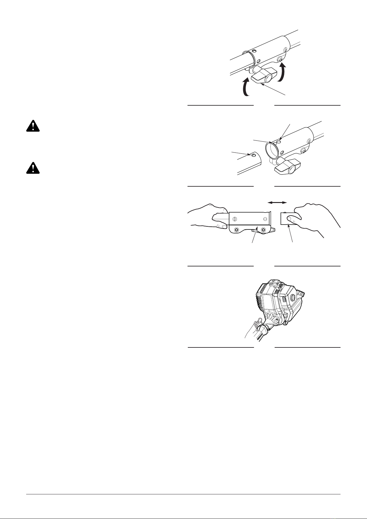
The handle can be adjusted for location on the shaft
and for angle of grip. To adjust handle:
1. Flip the lever down and turn the nut counterclockwise
to loosen the handle (Fig. 2).
2. Hold the unit in the operating position. Move the
handle up or down the shaft housing to a comfortable
location. Make sure the handle is positioned beyond
the end of the safety label.
3. Tilt the handle to the preferred grip angle.
4. Tighten the knob clockwise and ip the lever up to
secure the handle.
This product requires assembly. Carefully remove the
product and any accessories from the box. Make sure
that all items listed in the packing list are included.
Inspect the product carefully to make sure no breakage
or damage occurred during shipping.
Do not discard the packing material until you have
carefully inspected and satisfactorily operated the
product. If any parts are damaged or missing, please
call 1-800-261-3981 for assistance.
Do not use this product if any parts on the packing
list are already assembled to your product when you
unpack it. Parts on this list are not assembled to the
product by the manufacturer and require customer
installation. Use of a product that may have been
improperly assembled could result in serious personal
injury.
To prevent an accidental start that could cause serious
personal injury, always disconnect the engine spark
plug wire from the spark plug when assembling parts.
Before using any attachment, read and understand the
manual that came with the attachment. Follow all safety
information contained within.
To avoid serious personal injury and damage to the
unit, shut the unit off before removing or installing an
attachment.
In addition to the supplied line trimmer lower shaft, the
coupler on the upper shaft enables the use of various
other lower shaft attachments, available for separate
purchase.
Never install, remove, or adjust any attachments while
power head is running. Failure to stop the engine can
cause serious personal injury.
WARNING:
WARNING:
WARNING:
WARNING:
WARNING:
Quantity Item
1Fast Start Guide
1Operator’s Manual
1Bump head (installed)
1Harness
1Fixed line head
1Black .130 in. line
1
Cutting head shield and mounting screw
1Torx wrench
1
Spark plug wrench
160 ml bottle of oil
1 Warranty statement
1 EPA warrantly letter
INSTALLING THE CUTTING HEAD
SHIELD
INSTALLING AND REMOVING THE
ATTACHMENT
ADJUSTING THE HANDLE
Fig. 2
Cutting Head
Shield
Screw
Tab
Mount
Bracket
Fig. 1
Slot
7WWW.SENIXTOOLS.COM
1. If present, remove the gray spacer from the coupler
opening.
2. Set the unit on a at, level surface.
3. Turn the knob counterclockwise to loosen the coupler
(Fig. 3).
4. Align the release button with the guide recess
(Fig. 4).
5. Push the attachment straight into the coupler until the
release button snaps rmly into the primary hole
(Fig. 5).
6. Turn the knob clockwise to tighten the coupler.
1. Set the unit on a at, level surface.
2. Turn the knob counterclockwise to loosen the coupler
(Fig. 3).
3. Press and hold the release button (Fig. 4).
4. Pull the attachment straight out of the coupler
(Fig. 5).
Before operating the unit, make sure the release button
is fully snapped into the primary hole and the knob is
securely tightened.
Unless specied otherwise, the release button should
be snapped into the primary hole only. Using the wrong
hole could lead to personal injury or damage to the unit.
The harness with quick release function can be hooked
behind the rear hand if needed (Fig. 5a).
NOTE: Harness use is optional.
CAUTION:
CAUTION:
Installing the Attachment
Removing the Attachment
INSTALL THE HARNESS
Tighten
Loosen
Knob
Fig. 3
Release Button
Guide Recess
Primary Hole
Fig. 4
Coupler Attachment
Fig. 5
Fig. 5a

8WWW.SENIXTOOLS.COM
OIL AND FUEL
Attempting to start the engine before it has been
properly lled with lubricant will result in
equipment failure not covered by the warranty.
Do not overll. Overlling the crankcase may cause
excessive smoke, oil loss, and engine damage.
OVERFILLING THE CRANKCASE MAY CAUSE
SERIOUS PERSONAL INJURY. Check the oil level
before each use. The importance of maintaining the
proper oil level cannot be overemphasized. Change the
oil according to the Maintenance Schedule.
Gasoline is extremely ammable. Ignited vapors may
explode. Always stop the engine and allow it to cool
before lling the fuel tank. Do not smoke while lling the
tank. Keep sparks and open ames at a distance from
the area.
Remove the fuel cap slowly to avoid injury from fuel
spray. Never operate the unit without the fuel cap
securely in place.
Add fuel in a clean, well-ventilated outdoor area. Wipe
up any spilled fuel immediately. Avoid creating a source
of ignition for spilled fuel. Do not start the engine until
fuel vapors dissipate.
Gasoline and its vapors are highly ammable and
explosive. To prevent serious personal injury and
property damage, handle it with care. Keep away from
ignition sources and open ames, handle outdoors only.
Pour fuel outdoors where there are no sparks or ames.
Slowly remove the fuel cap after stopping the engine.
Do not smoke while fueling. Wipe spiled fuel from unit.
Move at least 3 m (10 ft) away from the fueling source
before starting engine.
Always wear heavy, long pants, boots, gloves, and a
long-sleeve shirt. Do not wear loose clothing, jewelry,
short pants, sandals, or go barefoot. Secufe hair so it is
above shoulder level.
Use a high-quality SAE 30 weight oil. DO NOT use dirty
oil. Failure to use clean oil of the correct type can cause
premature engine wear and failure.
CAUTION:
CAUTION:
WARNING:
WARNING:
WARNING:
WARNING:
WARNING:
WARNING:
NOTE: This unit was shipped without oil in the
crankcase. Oil must be added before starting the unit.
NOTE: This unit comes with a 2.03 uid oz. (60 ml)
container of oil.
1. Set the unit on a at, level surface.
2. Unscrew the oil ll plug (Fig. 6).
3. Pour the entire container of oil into the oil ll hole. DO
NOT overll. Refer to Checking the Oil Level.
NOTE: Never add oil to the fuel tank. This unit has a
four-cycle engine. DO NOT mix oil with gasoline.
4. Wipe up any oil that may have spilled.
5. Reinstall the oil ll plug. Make sure the O-ring is in
place on the oil ll plug (Fig. 6).
1. Position the unit with the fuel cap facing up.
2. Slowly remove the fuel cap.
3. Place the fuel container spout into the fuel tank ll
hole and ll the tank. Stop adding gas when you see
that the level reaches the base of the tank spout
(Fig. 6a).
NOTE: Do not overll the tank.
4. Wipe up any fuel that may have spilled.
5. Reinstall the fuel cap.
6. Move the unit at least 30 ft. (9.1 m) from the fuel
container and the fueling site before starting the
engine.
USING THE RIGHT OIL
ADDING OIL: INITIAL USE
FUELING THE UNIT
Oil Fill Plug
Oil Fill Hole
O-Ring
Fig. 6
Fig. 6a
Base of
Tank Spout

9WWW.SENIXTOOLS.COM
STARTING AND STOPPING
Do not allow familiarity with this product to make you
careless. Remember that a careless fraction of a
second is sufcient to inict serious injury.
Operate this unit only in a well-ventilated outdoor area.
Carbon monoxide exhaust fumes can be lethal in a
conned area.
Avoid accidentally starting the unit. To avoid serious
injury, the operator and the unit must be in a stable
position when pulling the starter rope (Fig. 10).
Do not operate the unit inside a closed environment,
such as a room or building; breathing carbon monoxide
from exhaust fumes can kill.
Inspect unit before each use. Replace damaged parts.
Check for fuel leaks. Make sure all fasteners are in
place and secure. Replace cutting attachment parts that
are cracked, chipped, or damaged in any way. Make
sure the cutting attachment is properly installed and
securely fastened. Make sure the cutting attachment
shield is properly attached and in the position
recommended by the manufacturer. Use only exible,
nonmetallic line recommended by the manufacturer.
Never use, for example, wire or wire-rope, which can
break off and become a dangerous projectile.
Clear the area to be cut before each use. Remove
all objects such as rocks, broken glass, nails, wire,
or string which can be thrown or become entangled
in the cutting attachment. Clear the area of children,
bystanders, and pets outside a 50 ft (15 m) radius: there
is still a risk of injury from thrown objects outside the
50 ft (15 m) zone. Bystanders should be encouraged to
wear eye protection.
If you are approached, stop the engine and cutting
attachment. In the case of bladed units, there is the
added risk of injury to bystanders from being struck with
the moving blade in the event of a blade thrust or other
unexpected reaction of the saw.
Always wear eye protection with side shields marked to
comply with ANSI Z87.1, along with hearing protection.
Failure to do so could result in objects being thrown into
your eyes and other possible serious injuries.
Do not use any attachments or accessories not
recommended by the manufacturer of this product. The
use of attachments or accessories not recommended
can result in serious personal injury.
Operation of this equipment could create sparks that
can start res around dry vegetation. A spark arrestor
may be required. The operator should contact local
re agencies for laws or regulations relating to re
prevention requirements.
DO NOT USE E85 FUEL IN THIS UNIT.
It has been proven that fuel containing greater than
10% ethanol will likely damage this engine and void the
warranty.
WARNING: WARNING:
WARNING:
WARNING:
CAUTION:
CAUTION:
WARNING:
WARNING:
WARNING:
WARNING:
The use of old fuel is the most common cause of
performance problems. Use only fresh, clean unleaded
gaso- line.
NOTE: This unit has a four-cycle engine. DO NOT mix
oil with gasoline.
Today’s fuels are often a blend of gasoline and
oxygenates such as ethanol, methanol or MTBE
(ether). Alcohol-blended fuel ab- sorbs water. As little
as 1% water in the fuel can make fuel and oil separate,
forming acids when stored. ALWAYS use fresh fuel (less
than 30 days old) with less than 10% ethanol.
NOTE: Dispose of old fuel according to federal, state
and local regulations.
If using a blended fuel:
• Always use fresh unleaded gasoline
• Use the fuel additive STA-BIL® or an equivalent
Use a fuel additive, such as STA-BIL Fuel Stabilizer or
an equivalent, to inhibit corrosion and minimize gum
deposits. Add 0.8 oz. (23 ml) of fuel additive per gallon
of fuel, according to the instructions on the container.
NEVER add fuel additives directly to the unit’s fuel tank.
1. Check the oil level. Refer to Checking the Oil Level.
2. Fill the fuel tank. Refer to Fueling the Unit.
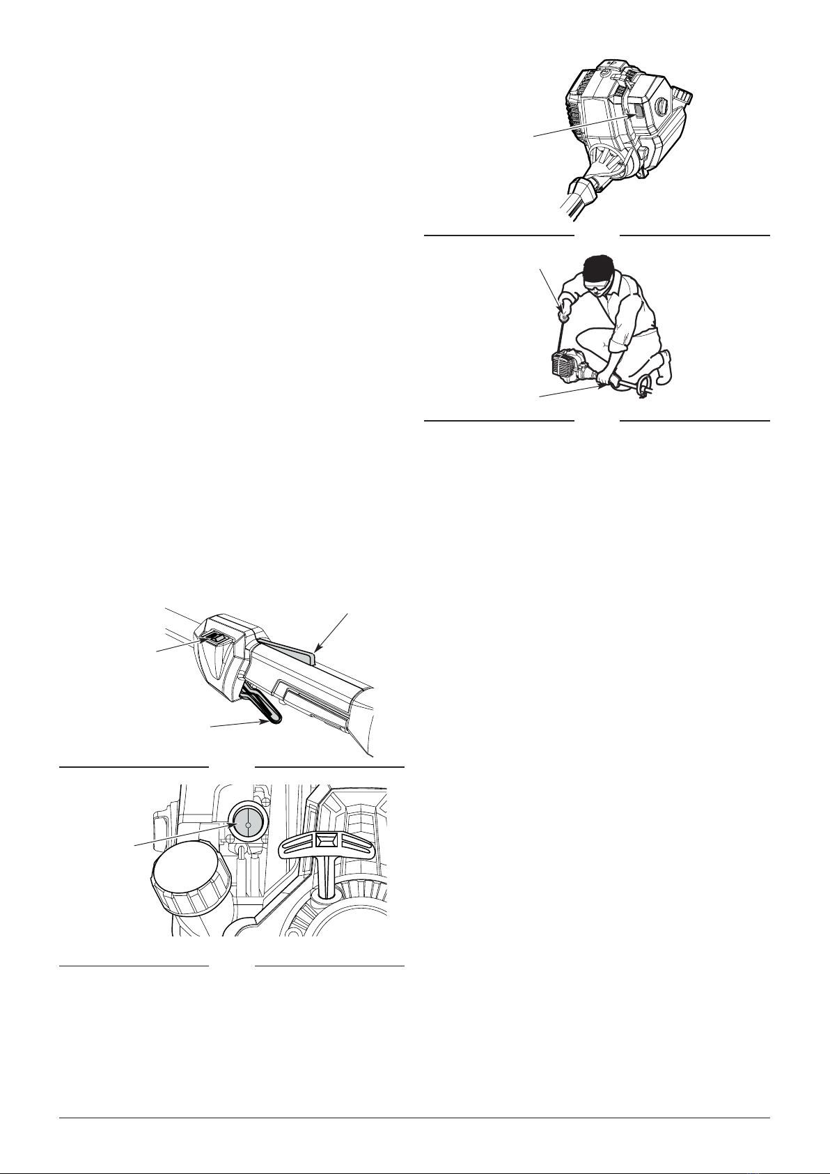
NOTE: There is no need to turn the unit on. The On/Off
switch is in the On ( I ) position at all times (Fig. 7).
3.Slowly press and release the primer bulb 10 times
(Fig. 8).
4. Push the choke button in until it clicks (Fig. 9).
5. Crouch in the starting position (Fig. 10).
NOTE: The choke automatically disengages when the
throttle lockout and throttle are pressed.
6. Pull the starter rope with a controlled and steady
motion 5 times to start the engine (Fig. 10). Allow the
USING THE RIGHT FUEL
Denition of Blended Fuels
Using Blended Fuels
STARTING INSTRUCTIONS
Using Fuel Additives
10 WWW.SENIXTOOLS.COM
STOPPING INSTRUCTIONS
engine to warm up for 30 to 60 seconds at idle speed
before increasing cutting speed.
7. To increase trimmer cutting speed, press and hold
the throttle lockout with one hand, and then squeeze
the throttle control with the other. The further you
squeeze the throttle control, the more the cutting
speed will increase (Fig. 7).
NOTE: The lockout will remain engaged as long as the
throttle control is being squeezed.
NOTE: To prevent the throttle control from being
squeezed accidentally, this unit has a throttle lockout.
The throttle control cannot be squeezed unless the
throttle lockout is also engaged.
IF... the engine does not start, begin the starting
procedure with step 3.
IF... the engine fails to start after 3 attempts: Press and
hold the throttle lockout. Squeeze and hold the throttle
control. Pull the starter rope with a controlled and
steady motion until the unit starts.
IF... the engine stops while the throttle control is
squeezed, begin the starting procedure with step 3.
IF THE ENGINE IS HOT... begin the starting procedure
with step 4.
1. Release the throttle control and allow the engine to
idle.
2. Press and hold the On/Off switch in the Off (O)
position until the engine comes to a complete stop
(Fig. 7). Make sure the cutting attachment has
stopped before the unit is set down.
Throttle Control
On/Off Switch
(I = On / STOP = Off)
Throttle
Lockout
Fig. 7
Primer Bulb
Fig. 8
Choke
Fig. 9
Starting
Position
Throttle Control
Starter Rope Grip
Fig. 10
11WWW.SENIXTOOLS.COM
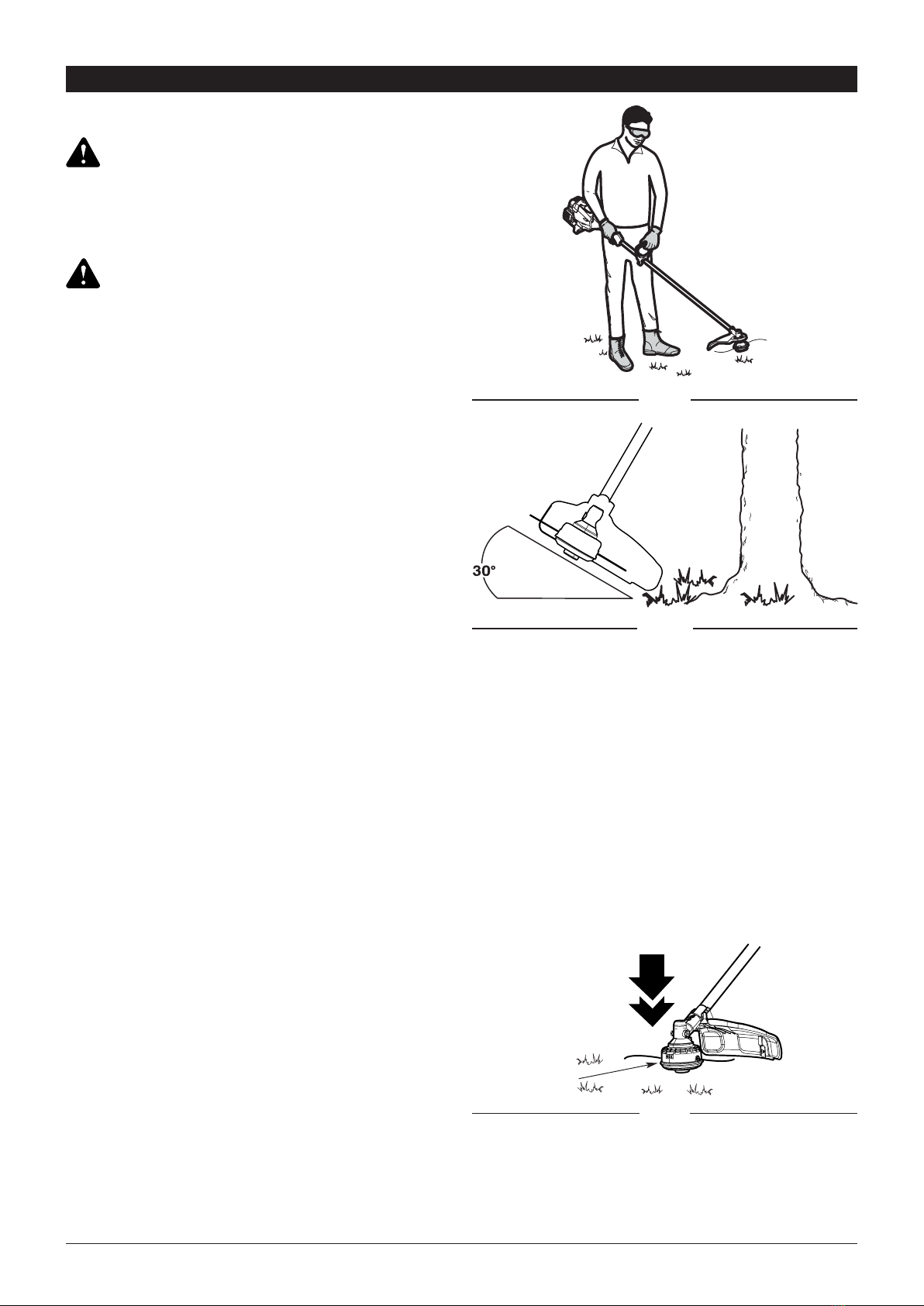
• Stand in the operating position (Fig. 11). Stand up
straight. Do not bend over.
• Keep feet apart and rmly planted.
• Hold the shaft grip with the right hand. Keep the right
arm slightly bent.
• Hold the handle with the left hand. Keep the left arm
straight.
• Hold the unit at waist level.
• Position the cutting head a few inches above the
ground.
• Do not over-reach; Keep all parts of your body away
from the rotating cutting attachment and hot surfaces.
• To direct clippings away from you, whenever possible
swing the trimmer in a left to right cutting motion.
There is an embossed arrow on the top of the safety
guard indicating the preferred left to right direction of
trimmer operation.
OPERATION
Always wear eye, hearing, hand, foot and body
protection to reduce the risk of injury when operating
this unit. Keep all parts of your body away from the
rotating cutting attachment and hot surfaces.
To prevent serious personal injury, avoid arm contact
with the engine while operating the unit. The engine
may be extremely hot.
When trimming around trees, posts, fences, etc., rotate
the whole unit so that the cutting head is at a 30° angle
to the ground (Fig. 12).
Maintaining the Trimming Line
Hard surfaces, such as sidewalks, can cause the
trimming line to wear down quickly or break.
• Frequently check the trimming line length. Replace
the trimming line as needed. Refer to Replacing the
Trimming Line.
• DO NOT force the unit. Make shallow cuts in as many
passes as are necessary to achieve the desired
depth. Cut at a slow, even pace.
This unit is equipped with a bump head. Trimming line
can be released from the cutting head without stopping
the engine. To release more line, lightly tap the bump
knob on the ground (Fig. 13) while operating the unit at
high speed. For best results, tap the bump knob on bare
ground or hard soil. Attempting to release line in tall
grass may stall the engine.
NOTE: Do not rest the cutting head on the ground while
the unit is running.
Each time the bump knob is tapped, about 1 inch (25.4
mm) of trimming line is released.
NOTE: Always keep the trimming line fully extended.
Line release becomes more difcult when the cutting
line gets shorter.
• Avoid hot surfaces by always keeping the tool away
from your body.
• Cut all grass from top to down. This will prevent grass
from wrapping around the shaft housing and string
head which could cause damage from overheating.
• If grass becomes wrapped around the string head,
STOP THE ENGINE, disconnect the spark plug wire,
and remove the grass.
• Use the tip of line to trim grass; do not force string
head into uncut grass.
• Avoid trees, owers, stones, walls and other objects
which can cause the line to break.
• Check and feed the line regularly to maintain full
cutting width and performance.
WARNING:
WARNING:
HOLDING THE UNIT
DECORATIVE TRIMMING
ADJUSTING THE TRIMMING LINE
TRIMMING TIPS
Fig. 11
Fig. 12
Bump Knob
Fig. 13

12 WWW.SENIXTOOLS.COM
Do not remove or alter the line cutting blade assembly.
Excessive line length will make the unit overheat. This
may lead to serious personal injury or damage to the
unit.
• To direct clippings away from the operator, tilt the
cutting head slightly down to the right; whenever
possible swing the trimmer in a left to right cutting
motion. There is an embossed arrow on the top of
the safety guard indicating the preferred left to right
direction of trimmer operation.
• Do not trim wet grass or weeds.
NOTE: Some line breakage will occur from:
• Entanglement with foreign matter
• Normal line fatigue
• Attempting to cut thick vegetation
• Forcing the line into objects such as walls or fence
posts
CAUTION:
TIPS FOR BEST RESULTS
13WWW.SENIXTOOLS.COM
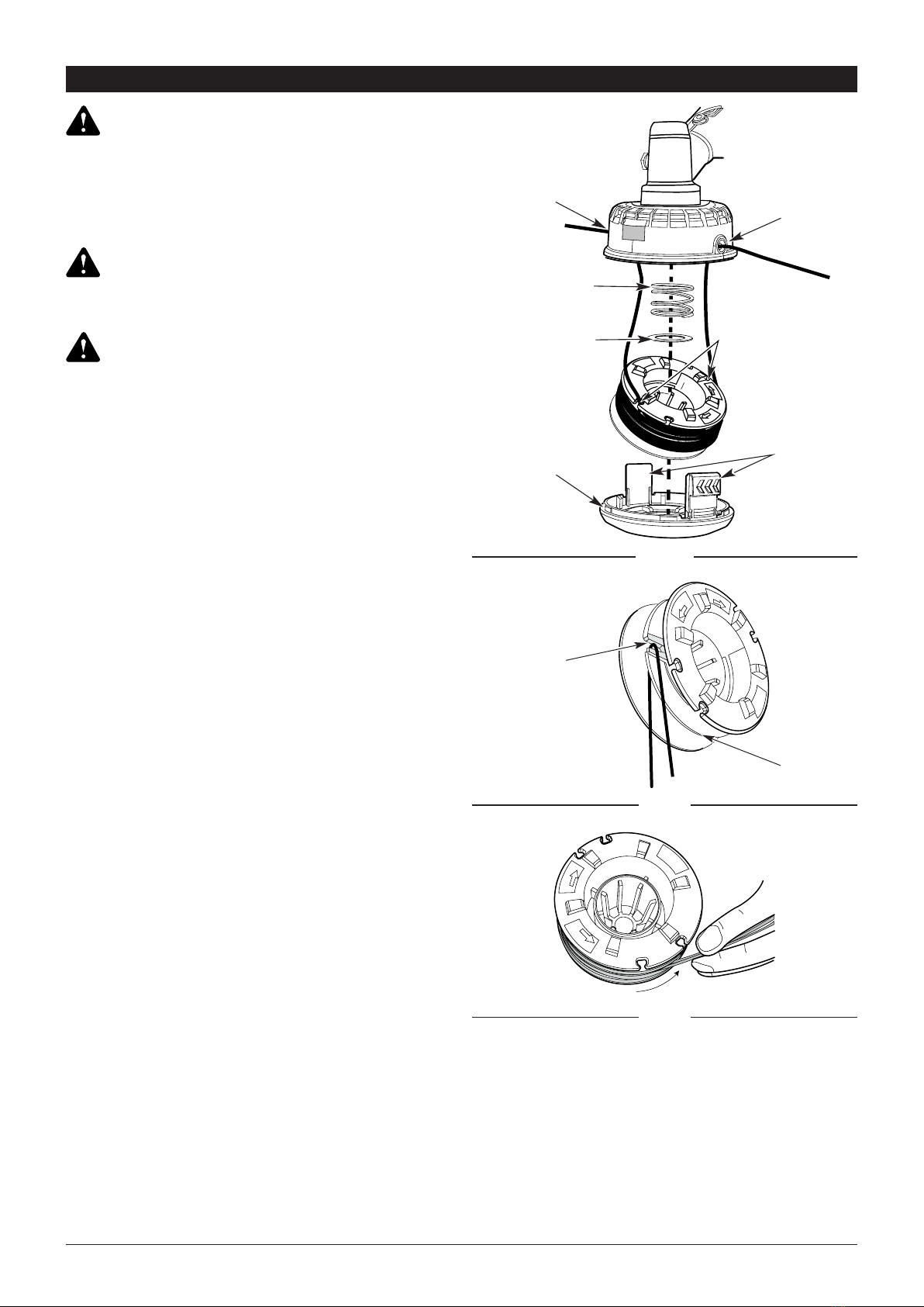
1. Push in the tabs on the side of the spool retainer and
pull to remove (Fig. 14).
2. Install the spring, washer, and rewound spool,
making sure that the lines are captured in the holding
slots on the new spool.
NOTE: Make sure that the ends of the lines extend
approximately 6 in. (152 mm).
3. Install the new spool so that the line ends align with
the eyelets in the cutting head, and thread the line
ends through the eyelets.
4. Pull the lines extending from the cutting head so that
the strings release from the slots in the spool.
5. Install the spool retainer by pressing the tabs into the
slots and pushing down on the spool until the spool
retainer clicks into place (Fig. 14).
1. Remove the spool from the cutting head.
2. Remove any old line from the spool. Use a clean
cloth to clean the surface of the cutting head.
3. Cut a 15 ft. (4.5 m) length of 0.095 in. (2.4 mm)
diameter trimming line.
4. Bend the line at the midpoint and insert the bend into
the holding slot on the spool (Fig. 15).
5. Wrap the line evenly and rmly around the spool
(Fig. 16).
6. Position the lines in the spool holding slots (Fig. 14).
7. Install the spool in the cutting head. See Replacing
the Spool.
REPLACING THE SPOOL (BUMP HEAD)
REPLACING THE TRIMMING LINE
(BUMP HEAD)
MAINTENANCE
To avoid serious personal injury, always stop the engine
and allow it to cool before cleaning or maintaining the
unit. Never perform cleaning or maintenance while
the unit is running. Disconnect the spark plug wire to
prevent the unit from starting accidentally.
Wear protective clothing and observe all safety
instructions to prevent serious personal injury.
Never use metal-reinforced line, wire, chain or rope.
These can break off and become dangerous projectiles.
Only use the trimming line described in the
Specications section.
Other types of trimming line may cause the unit to
overheat or fail.
WARNING:
WARNING:
WARNING:
Fig. 14
Washer
Spring
Eyelet
Eyelet
Holding Slots
Tabs
Spool
Retainer
Holding Slot
Split Wall
Fig. 15
Fig. 16
14 WWW.SENIXTOOLS.COM
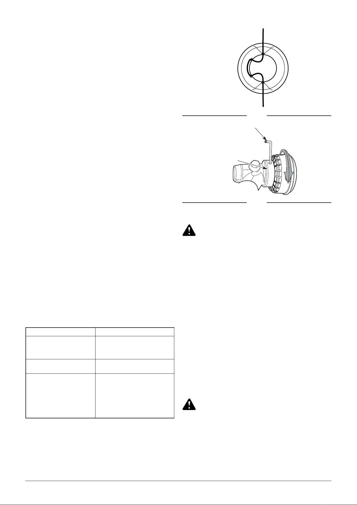
Cut a 16.25 in. length of 0.095 in. (2.4 mm) diameter
line and thread it through the trimmer head (Fig. 17).
NOTE: To avoid vibration, make sure that equal lengths
of line protrude through each side of the
trimmer head.
NOTE: Several 16.25 in. lengths of black 0.130 in. (3.3
mm) spiral Line are supplied with this trimmer. This line
is designed for cutting larger weeds and light brush.
Perform these required maintenance procedures at the
frequency stated in the table. These procedures should
also be a part of any seasonal tune-up.
NOTE: Some maintenance procedures may require
special tools or skills. If you are unsure about these
procedures, take the unit to a qualied service dealer.
NOTE: Maintenance, replacement, or repair of the
emission control devices and system may be performed
by a qualied service dealer.
NOTE: Please read the California/EPA statement that
came with the unit for a complete listing of terms and
coverage for the emissions control devices, such as the
spark arrestor, mufer, carburetor, etc.
REPLACING THE TRIMMING LINE
(FIXED LINE)
MAINTENANCE SCHEDULE
CHANGING THE CUTTING HEAD FROM
BUMP TO FIXED
CHECKING THE OIL LEVEL
Inspecting the Oil Level
Adding Oil
1. Insert the Torx wrench into the locking hole on the top
of the gear box (Fig. 18).
2. Apply light pressure on the wrench while turning the
bump head clockwise. At a certain point you will feel
the head catch on the wrench when the wrench tip
slips into the notch on the head collar.
3. Continue turning head clockwise to unscrew and
remove the head from the arbor.
4. Screw the xed head counterclockwise onto the arbor
until securely tightened (Fig. 18a). Remove the Torx
wrench from the locking hole.
5. To reinstall the bump head, perform the preceding
instructions in the opposite order and manner.
1. Stop the engine and allow it to cool.
2. Set the unit on a at, level surface, such as a
workbench or table. The cutting head shield should
hang over the edge so that the engine is level
(Fig. 19).
NOTE: Failure to keep the engine level may result in a
faulty oil level reading.
3. Unscrew the oil ll plug. The oil level should be visible
on the rst thread of the oil reservior (Fig. 20). If the
oil level is too low, add oil. Refer to Adding Oil.
1. Clean the area around the oil ll plug (Fig. 20) to
prevent debris from entering the oil ll hole.
2. Unscrew the oil ll plug.
3. Add oil to the oil ll hole until the oil level is visible on
the rst thread of the oil reservoir (Fig. 20).
FREQUENCY MAINTENANCE REQUIRED
Every 10 hours
• Clean and re-oil the air lter.
Refer to
Maintaining the Air
Filter.
Every 20 hours • Change the oil. Refer to
Changing the Oil.
After the rst 10 hours and
at 38 hours
• Have the rocker arm
clearance checked by a
qualied service dealer.
• Check the spark plug
condition and gap. Refer to
Maintaining the Spark Plug.
Fig. 17
Torx Wrench
Fig. 18
Locking Hole
Check the oil level before each use. The importance
of maintaining the proper oil level cannot be
overemphasized.
DO NOT overll the oil level. Overlling will result in
too much oil in the engine crankcase, and may cause
smoke or fumes that can injure the user.
WARNING:
WARNING:
• If the oil level is too high, tip the unit and drain the
excess oil into an appropriate container.
4. Wipe up any oil that may have spilled.
5. Make sure the O-ring is in place on the oil ll plug
(Fig. 21).
6. Reinstall the oil ll plug.

15WWW.SENIXTOOLS.COM
CHANGING THE OIL
MAINTAINING THE AIR FILTER
Old engine oil is considered special waste and has
to be disposed according to your local environment
protection regulation. Do not pour the oil into a garbage
can, sewer, soil etc.
DO NOT overll the oil level. Overlling will result in
too much oil in the engine crankcase, and may cause
smoke or fumes that can injure the user.
WARNING:
WARNING:
Change the oil while the engine is still warm. The oil will
ow freely and carry away more impurities.
1. Clean the area around the oil ll plug (Fig. 20) to
prevent debris from entering the oil ll hole.
2. Unscrew the oil ll plug.
3. Tip the unit vertically to pour the oil out of the oil ll
hole and into a container (Fig. 22). Allow ample time
for complete drainage.
NOTE: Dispose of the old oil according to federal, state
and local regulations.
4. Wipe up any oil that may have spilled.
5. Pour 2.03 .oz. (60 ml) of SAE 30 oil into the oil ll
hole.
6. Wipe up any oil that may have spilled.
7. Make sure the O-ring is in place on the oil ll plug
(Fig. 21).
8. Reinstall the oil ll plug.
Failure to maintain the air lter can result in poor
performance or can cause permanent damage to
the engine. Engine failure due to improper air lter
maintenance is not covered by the product warranty.
Cleaning the Air Filter
1. Unscrew the cover screw completely. Remove the air
lter cover from the air lter housing (Fig. 23).
2. Remove the air lter from the air lter housing.
3. Wash the air lter in detergent and water. Rinse the
air lter thoroughly and allow it to dry.
4. Reinstall the air lter in the air lter housing (Fig. 23).
NOTE: Operating the unit without the air lter and air
lter cover will VOID the warranty.
5. Insert the tab on the air lter cover into the hole in the
air lter housing. Push the air lter cover back onto
the air lter housing. Insert the cover screw into the
air lter cover. Tighten the cover screw to secure the
air lter cover (Fig. 23).
NOTE: Do not overtighten as this may strip the screw.
Fig. 19
Fig. 20
Oil Visible on
First Thread
Fig. 21
O-ring
Fig. 22
Cover Screw
Air Filter
Cover
Air Filter
Housing
Air Filter
Fig. 23

16 WWW.SENIXTOOLS.COM
If the engine will not idle properly:
1. Start the engine. Refer to Starting and Stopping.
2. Release the throttle control and let the engine idle.
• If the engine stops, increase the idle speed. Use a
small Phillips screwdriver to turn the idle speed screw
clockwise, 1/8 of a turn at a time, until the engine
idles smoothly (Fig. 24).
• If the cutting head spins when the engine idles,
reduce the idle speed. Turn the idle speed screw
counterclockwise, 1/8 of a turn at a time, until the
cutting head stops moving (Fig. 24).
1. Stop the engine and allow it to cool. Grasp the spark
plug boot rmly and pull it from the spark plug.
2. Clean around the spark plug. Remove the spark plug
from the cylinder head with a 5/8-inch socket, turning
counterclockwise.
NOTE: A 5/8-inch spark plug wrench is supplied with
this trimmer.
3. Inspect the spark plug. If the spark plug is cracked,
fouled or dirty, replace it with replacement part
#AM5RC or an equivalent spark plug.
4. Use a feeler gauge to set the air gap at 0.6 mm - 0.8
mm (0.025 in. - 0.31 in.) (Fig. 25).
5. Install the spark plug in the cylinder head. Tighten the
spark plug with a 5/8-inch socket, turning it clockwise
until snug.
NOTE: If using a torque wrench, torque to 18 N•m (159
in.•lb.). Do not over tighten.
6. Reattach the spark plug boot.
ADJUSTING THE IDLE SPEED
MAINTAINING THE SPARK PLUG
The cutting head will move when adjusting the idle
speed. Wear all protective clothing and keep all
bystanders, children, and pets at least 50 ft. away. Make
adjustments with the unit supported by hand so that the
cutting head does not contact the ground or any object.
Keep all parts of your body away from the cutting head
and mufer. Failure to follow these instructions could
result in serious personal injury.
Do not remove the spark plug when the engine is hot.
Do not sand blast, scrape or clean spark plug
electrodes. Grit in the engine could damage the
cylinder.
The cutting attachment should never turn at idle. Turn
the idle speed screw counterclockwise to reduce the
idle RPM and stop the cutting attachment, or contact
customer support for adjustment and discontinue use
until the repair is made. Serious personal injury could
result from the cutting attachment turning at idle.
WARNING:
CAUTION:
CAUTION:
WARNING:
Fig. 24
Idle Speed Screw
Primer Bulb
Fig. 25
(0.025 in. - 0.31 in.)
0.60 mm - 0.80 mm

17WWW.SENIXTOOLS.COM
• Never store a fueled unit where fumes may reach an
open ame or spark.
• Allow the engine to cool before storing.
• Lock up the unit to prevent unauthorized use or
damage.
• Store the unit in a dry, well-ventilated area.
• Store the unit out of the reach of children.
Short-term Storage (1-2 weeks)
Store the unit in a horizontal position. If not possible,
store the unit vertically with the engine at the top.
Long-term Storage
1. Remove the fuel cap, tip the unit and drain the fuel
into an approved container. Reinstall the fuel cap.
2. Start the engine and allow it to run until it stalls.
This ensures that all fuel has been drained from the
carburetor.
3. Allow the engine to cool. Remove the spark plug
and put 5 drops of any high quality motor oil into the
cylinder. Pull the starter rope slowly to distribute the
oil. Reinstall the spark plug.
4. Thoroughly clean the unit and inspect it for any loose
or damaged parts. Repair or replace damaged parts
and tighten loose screws, nuts or bolts.
5. Store the unit in a horizontal position. If horizontal
storage is not possible, store unit vertically with
engine at top.
Preparing the Unit for Use after Long-term
Storage
1. Remove the spark plug. Tip the unit and drain all of
the oil from the cylinder into an approved container.
Reinstall the spark plug.
2. Change the oil. Refer to Changing the Oil.
NOTE: Do not use fuel that has been stored for more
than 30 days. Dispose of old fuel and oil according to
federal, state and local regulations.
TRANSPORTATION
Transport the unit in a horizontal position. If not
possible, transport the unit vertically with the engine at
the top. Secure the trimmer shaft to prevent damage
during transport.
CLEANING
STORAGE
CLEANING AND STORAGE
To avoid serious personal injury, always stop the engine
and allow it to cool before cleaning or maintaining the
unit.
Use a small brush to clean the outside of the unit. Do
not use strong detergents. Household cleaners that
contain aromatic oils such as pine and lemon, and
solvents such as kerosene, can damage plastic. Wipe
off any moisture with a soft cloth.
WARNING:

18 WWW.SENIXTOOLS.COM
TROUBLESHOOTING
THE ENGINE WILL NOT START
The fuel tank is empty Fill the fuel tank with fresh fuel
The primer bulb was not pressed enough Press the primer bulb 10 times
The fuel is old (over 30 days) Drain the fuel tank and add fresh fuel
The spark plug is fouled Replace the spark plug
THE ENGINE WILL NOT IDLE
The air lter is dirty Clean or replace the air lter
The fuel is old (over 30 days) Drain the fuel tank and add fresh fuel
THE ENGINE WILL NOT ACCELERATE
The fuel is old (over 30 days) Drain the fuel tank and add fresh fuel
The cutting head is bound with grass Stop the engine and clean the cutting head
The air lter is dirty Clean or replace the air lter
THE ENGINE LACKS POWER OR STALLS
The fuel is old (over 30 days) Drain the fuel tank and add fresh fuel
The air lter is dirty Clean or replace the air lter
The spark plug is fouled Replace the spark plug
If further assistance is required, take the unit to a qualied service dealer.
PROBLEM SOLUTION

19WWW.SENIXTOOLS.COM
PARTS
No. Part # Description Qty.
1103001000297 Engine head 1
2201999001337 Tube xed circle 1
3207310100743 Screw 1
4207320100013 Hexagon nut 2
5199999001314 - 1
6199004000604 Handle assembly 1
6-1 207310100263 Screw 6
6-2 202024002102 Hand shank 1
6-3 199081000107 Cable assembly 1
6-4 199999001152 Stopping wire 1
6-5 207180200023 Switch 1
6-6 202024002101 Hand shank 1
6-7 202042000207 Driving lever 1
6-8 202004000897 Trigger 1
6-9 303000003 Wire cover 1
6-10 207019900345 Return spring 1
6-11 202999001491 Control circle 1
7 201024000009 Harness ring 1
8 208008000051 Harness 1
9 199004000605 Handle assembly 1
9-1 202028000109 Knob 1
No. Part # Description Qty.
9-2 202999001665 Front handle seat 1
9-3 201026000343 Shaft 1
9-4 202024002114 Hand shank 1
9-5 202004000898 Trigger 1
9-6 207199900105 Center support pin 1
10 202028000102 Knob 1
11 199048000132 Shield screen assy’ 1
11-1 202012000417 Shield 1
11-2 201057000219 Clamp 1
11-3 207310101121 Screw 1
11-4 201045000165 Blade 1
12 202023000077 Plug 1
13 199999001284 Front straight pipe
assembly 1
14 207310100738 Screw 1
15 199999001283 Gear box assembly 1
16 201999001339 Fixed tray 1
17 199023000066 Grass head assy’ 1
18 208008000040 Wrench 1
19 207179900014 Trigger 1
20 202999001673 Oil pot 1

20 WWW.SENIXTOOLS.COM
WARRANTY
LIMITED THREE-YEAR WARRANTY
Additional Limitations
3-year limited warranty on all Senix 4QL series gasoline powered equipment. FOR THREE YEARS from the
original date of retail purchase this Senix product is warranted against defects in materials or workmanship on
power tools. Defective product will receive free repair.*
This warranty does not cover normal wear of parts and components such as cutting chain, line or blades nor does
this warranty cover product transportation cost for warranty or service.
Any implied warranty granted under state law, including warranties of merchantability or tness for a particular
purpose, are limited to three years from the date of purchase on power tools and chargers and seven years on
batteries. The manufacturer is not responsible for direct, indirect, incidental or consequential damages. Some
states and provinces do not allow limitations on how long an implied warranty lasts and/or do not allow the
exclusion or limitation of incidental damages, so the above limitations and exclusions may not apply to you. This
warranty gives you specic legal rights, and you may also have other rights which vary from state to state or
province to province.
The YAT USA declines any responsibility in regard to civil liability arising from abusive use or not in conformity with
proper use and maintenance of the machine as described in the operator’s manual.
YAT USA is not responsible for direct, indirect, incidental or consequential damages.
After the purchase, the manufacturer recommends proper maintenance of the machine and to read the operator’s
manual before using the machine.
*Original purchase receipt may be required for proof of purchase
For customer service contact us toll free at 1-800-261-3981 or Senixtools.com.
YAT USA, Inc. 9048 E Bahia Dr, suite 105, Scottsdale, AZ 85260
Warranty is subject to the following conditions:
• Warranty applies to the original purchaser at retail and is not transferrable*
• Warranty Registration at www.senixtools.com
• The tool has not been misused, abused, neglected, altered, modied or repaired by anyone other than an
authorized service center
• Only genuine Senix accessories have been used with or on this product
• The tool has been subjected to normal wear and tear
• The tool has not been used for trade or professional purposes
• The tool has not been used for rental purposes
• This warranty only covers defects arising under normal usage and does not cover any malfunction, failure or
defect resulting from misuse, abuse (including overloading the product, exposure to water or rain) accidents,
neglect or lack of proper installation and improper maintenance or storage.
To locate your nearest Senix service provider call toll free at 800-261-3981 or email us at [email protected].
Table of contents
Languages:
Other Senix Trimmer manuals

Senix
Senix GTBCU4QL-M User manual

Senix
Senix GTX2-M User manual

Senix
Senix HTPX2-M User manual

Senix
Senix HTE3.8-L User manual

Senix
Senix GTE2.5-L-EU User manual

Senix
Senix GTC4QL-L User manual

Senix
Senix GTSX5-M-0 User manual

Senix
Senix HTX2-M User manual

Senix
Senix HT4QL-L User manual

Senix
Senix HTX5-M User manual


