Senix GTBCU4QL-M User manual

4-Cycle 1.9 cu in. (31 cc) Engine Gasoline
Powered Grass Trimmer/Brush Cutter 2 in 1
Model: GTBCU4QL-M
Operator's manual
TM
For customer support, please call 1-800-261-3981 or send email to:
SAVE THIS MANUAL FOR FUTURE REFERENCE

EN - 2 WWW.SENIXTOOLS.COM
4
2
1
3
8
6
5
9
7
15
16
18
17
12
19
13
11
10
14
1
23
Mount Bracket
Mounting Disc
Blade
Washer
Floating Disc
Locknut
Screw
Tab
Cutting Head Shield

3 - EN
WWW.SENIXTOOLS.COM
4
6
98
7
5
Mounting Disc
Cutting Head
Upper Fixed Cover
Tighten
Loosen
Knob
Lower Fixed Cover
Locating Hole
Low Shaft
Coupler
Knob
Locating Button
Oil Fill Plug
O-Ring
Oil Fill Hole
Handle Support

EN - 4 WWW.SENIXTOOLS.COM
滚滚长江东逝水
滚滚长江东逝水
Starter rope
10
13
15
12
14
On/Off Switch
Throttle Lockout
Choke Button
Throttle Control
Primer Bulb
Starter Rope
Base of Fuel Tank Spout
11
5 - EN
WWW.SENIXTOOLS.COM
17
19
19
21
21
18
18
20
20
Bump Knob
Holding Slot
Split Wall
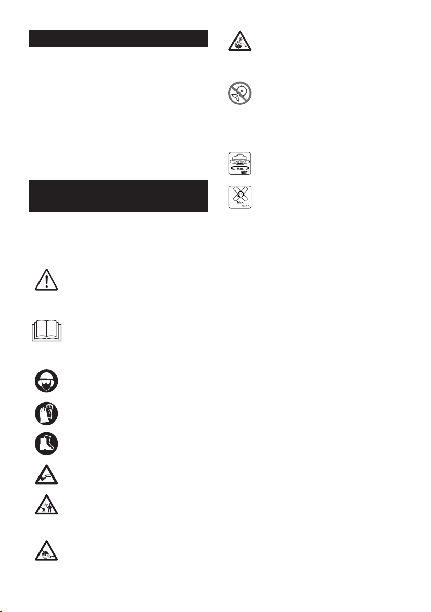
Oil Visible on First Thread
16
Eyelet
Spring
Washer
Spool Retainer
Holding Slots
Eyelet
Tabs
EN - 6 WWW.SENIXTOOLS.COM
22
24
23
Idle Speed Screw
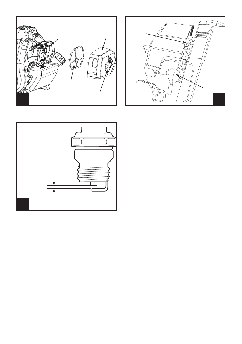
0.60mm - 0.80mm
0.025in. - 0.031in.
Primer Bulb
Cover Rotary Knob
Air Filter Housing Air Filter Cover
Air Filter
7 - EN
WWW.SENIXTOOLS.COM
TABLE OF CONTENTS
SAFETY & INTERNATIONAL SYMBOLS ...........................7
SAFETY INSTRUCTIONS...................................................8
KNOW YOUR UNIT............................................................13
SPECIFICATIONS*............................................................13
ASSEMBLY.........................................................................13
OIL AND FUEL...................................................................14
OPERATION.......................................................................15
MAINTENANCE..................................................................17
TROUBLESHOOTING.......................................................20
PARTS................................................................................21
WARRANTY.......................................................................23
SAFETY & INTERNATIONAL
SYMBOLS
Explanation of Safety & international symbols describes
safety and international symbols and pictographs that may
appear on this product. Read the operator’s manual for
complete safety, assembly, operating and maintenance and
repair information.
This graphic accompanied by the words
WARNING, DANGER OR CAUTION calls
attention to an act of a condition which can
lead to SERIOUS INJURY.
Read the operator’s manual(s) and follow all
warnings and safety instructions. Failure to do
so can result in serious injury to the operator
and/or bystanders.
Always wear eye protection, ear protection and
head protection meeting ANSI Z87.1 standards.
Wear gloves.
Wear foot protection.
Beware of foot injury by cutting attachment.
Keep 15 meters or 50 feet away from any other
person.
Beware of objects ung by cutting
attachments.
Never use without properly mounted protection
guard.
Beware of objects ung by cutting
attachments.
Never use without properly mounted protection
guard.
Don’t install or use any type of blade on the unit
displaying this symbol.
Bystander sound pressure level: 75dB(A).
Maximum permitted revolutions of the cutting
head.
Maximum permitted revolutions of the blade.
75dB(A)
MEASURED AT 50FT. (15M)
PER ANSI B175.3
5700
5700

EN - 8 WWW.SENIXTOOLS.COM
SAFETY INSTRUCTIONS
WARNING!
Signals a SERIOUS hazard.
Failure to obey a safety WARNING
symbol CAN result in serious injury
to yourself or to others.
NOTE:
Advises you of information or
instructions vital to the operation or
maintenance of the equipment.
WARNING!
Crude oil, gasoline, diesel fuel
and other petroleum products can
expose you to chemicals including
toluene and benzene, which are
known to the State of California to
cause cancer and birth defects or
other reproductive harm. These
exposures can occur in and around
oil elds, reneries, chemical plants,
transport and storage operations
such as pipelines, marine terminals,
tank trucks and other facilities and
equipment. For more information
go to: www.P65Warnings.ca.gov/
petroleum.
WARNING!
CALIFORNIA PROPOSITION 65
This product contains a chemical
known to the state of California to
cause cancer, birth defects or other
reproductive harm.
Read the operator’s manual and
follow all warnings and safety
instructions. Failure to do so
can result in serious injury to the
operator and/or bystanders.
SAFETY WARNINGS
1. Proper safety precautions must
be observed. Like all power
equipment this unit must be
handled carefully. DO NOT
EXPOSE YOURSELF OR
OTHERS TO DANGER. Follow
these general rules. Do not
permit others to use this unit
unless they are thoroughly
responsible and have read, and
understood the string trimmer
manual and are trained in its
operation.
2. Always wear heavy, long pants,
boots, gloves, and a long-sleeve
shirt. Do not wear loose clothing,
jewelry, short pants, sandals, or
go barefoot. Secure hair so it is
above shoulder level.
3. Inspect unit before each use.
Replace damaged parts.
Check for fuel leaks. Make
sure all fasteners are in place
and secure. Replace cutting
attachment parts that are
cracked, chipped, or damaged in
any way. Make sure the cutting

9 - EN
WWW.SENIXTOOLS.COM
7. Do not operate the unit in
insufcient lighting conditions.
8. Do not operate this unit when
tired, ill, or under the inuence of
alcohol, drugs, or medication.
9. Always use proper handles when
trimming.
10. Do not smoke while lling tank.
11. Do not ll fuel in an enclosed
room or near open ames.
Ensure adequte ventilation.
12. Always store fuel in a properly
marked container that is
approved by local codes and
ordinances for such usage.
13. Never remove the fuel tank cap
while the engine is running.
14. Do not operate the unit inside
a closed environment, such as
a room or building; breathing
carbon monoxide from exhaust
fumes can kill.
15. Never attempt to make engine
adjustments while the unit is
running. Always make engine
adjustments with the unit resting
on a at, clear surface.
16. Do not use the unit if it is
damaged or poorly adjusted.
Never remove the unit’s guard.
Serious injury to the operator or
bystanders could result as well
as damage to the machine.
17. Clear the area to be cut before
attachment is properly installed
and securely fastened. Be sure
the cutting attachment shield
is properly attached and in the
position recommended by the
manufacturer. Use only exible,
nonmetallic line recommended
by the manufacturer. Never use,
for example, wire or wire-rope,
which can break off and become
a dangerous projectile.
4. DO NOT USE any attachment
with this power head other than
the ones recommended by the
manufacturer. Serious injury to
the operator or bystanders could
result as well as damage to the
machine.
5. The handles shall be mounted
in accordance with the
manufacturer’s instructions.
Do not attach any blade to a
unit without proper installation
of all required parts. Failure
to use the proper parts can
cause the blade to y off and
seriously injure the operator and/
or bystanders. Discard blades
that are bent, warped, cracked,
broken, or damaged in any way.
Use a sharp blade. A dull blade
is more likely to snag and thrust.
6. Keep the handles free from oil
and fuel.

EN - 10 WWW.SENIXTOOLS.COM
each use. Remove all objects
such as rocks, broken glass,
nails, wire, or string, which can
be thrown or become entangled
in the cutting attachment. Clear
the area of children, bystanders
and pets. At a minimum, keep
all children, bystanders and pets
outside a 15 m (50 ft) radius;
outside the 15 m (50 ft) zone,
there is still a risk of injury from
thrown objects. Bystanders
should be encouraged to wear
eye protection.
18. Never leave the unit unattended
while the engine is running.
19. Do not use this unit for any job
other than those for which it is
intended as described in this
manual.
20. Maintain rm footing and
balance. Do not over-reach.
Keep cutting attachment below
waist level. Maintain all parts of
your body away from the rotating
cutting attachment and hot
surfaces.
21. Do not use this type of unit for
sweeping away debris.
22. Use nylon cutting head which
is free of damage. If a stone
or any other obstacle is hit,
stop the engine and check the
nylon cutting head. A broken or
unbalanced nylon cutting head
must never be used.
23. FOLLOW INSTRUCTIONS for
assembling and operation.
24. Do not store the unit in a closed
area where fuel vapors can
reach an open ame from hot
water heaters, furnaces, etc.
Store in a locked, well ventilated
area only.
25. Ensure safe and proper
performance of your unit. Please
only use original accessories.
The use of any other
accessories or attachments
may cause a potential hazard or
injury to the user, damage to the
unit, and void the warranty.
26. If the unit will not be used for
a long time, clean the unit
completely, especially the fuel/oil
tank, its surroundings, and the
air lter.
27. When refueling, stop the engine
and conrm that it is cooled
down. Never refuel when the
engine is running or hot. When
gasoline spills, be sure to wipe
it up completely and dispose of
those materials before starting
the engine.
28. Mix and pour fuel outdoors
where there are no sparks and
flames. Slowly remove the fuel

11 - EN
WWW.SENIXTOOLS.COM
34. Pay attention to loosening and
overheating parts. If there is
any abnormality of the unit, stop
operation immediately and check
the unit carefully. If necessary,
have the unit serviced. Never
continue to operate a unit which
may be malfunctioning.
35. In start-up or during operation
of the engine, never touch hot
parts such as the mufer, the
high voltage wire, or the spark
plug.
36. After the engine has stopped,
the mufer is still hot. Never
place the unit in any places
where there are ammable
materials (dry grass, etc.),
combustible gasses, or
combustible liquids.
37. Pay special attention to
operation in the rain or just after
the rain as the ground may be
slippery.
38. If you slip or fall to the ground,
release the throttle lever
immediately.
39. Be careful not to drop the unit or
hit it against obstacles.
40. Before proceeding to adjust or
repair the unit, be sure to stop
the engine and detach the spark
plug.
41. When the machine is placed in
cap only after stopping the
engine. Do not smoke while
fueling or mixing fuel. Wipe
spilled fuel from the unit. Move
at least 3 m (10 ft) away from
the fueling source and site
before starting engine.
29. Stay clear of other workers
or bystanders by at least 15
meters/50 feet.
30. Whenever approaching an
operator of the unit, Be careful
not to startle or distract the
operator which can cause an
unsafe situation.
31. Never touch the nylon cutting
head or cutting blade whenever
the engine is running. If it is
necessary to adjust the protector
or nylon cutting head, make sure
to stop the engine and conrm
that the nylon cutting head or
blade has stopped running.
32. The engine should be turned off
when the unit is moved between
work areas.
33. Be careful not to hit the
nylon cutting head or blade
against stones, or the ground.
Unreasonable rough operation
will shorten the life of the unit
as well as create an unsafe
environment for yourself and
those around you.

EN - 12 WWW.SENIXTOOLS.COM
storage for a long time, drain
fuel/oil from the fuel/oil tank and
carburetor, clean the parts, and
move the machine to a safe
place.
42. Make periodic inspections
to ensure safe and efcient
operation.
43. Keep the unit away from re or
sparks.
44. Keep your body warm, especially
the head, neck, feet, ankles,
hands, and wrists.
45. Maintain good blood circulation
by performing vigorous arm
exercises during frequent work
breaks and also by not smoking.
46. Limit the hours of operation.
47. If you experience discomfort,
redness and swelling of the
ngers followed by whitening
and loss of feeling, consult
your physician before further
exposing yourself to cold and
vibration.
48. Always wear ear protection.
Loud noises for long periods
can cause hearing loss, even
permanent deafness.
49. Wear no-slip heavy duty work
gloves to improve your grip on
the handle. Gloves also reduce
the transmission of machine
vibration to your hands.
WARNING!
The string head is still dangerous
while the machine is coasting to a
stop.
50. Do not lay the machine on the
side; otherwise the fuel could
spill out.
51. Fuel evaporation during refueling
and exhaust gases are harmful
to the operator and people
around the unit.
52. Make sure that the fuel
evaporation and exhaust gases
will not drift to the face of
operator and keep other people
away from your working area.
53. Do not allow children or
untrained individuals to use this
unit.
54. Do not allow familiarity with this
product to make you careless.
Remember that a careless
fraction of a second is sufcient
to inict serious injury.
55. The cutting attachment may
be spinning during carburetor
adjustments. Wear your
protective equipment and
observe all safety instructions.
For units equipped with a clutch,
be sure the cutting attachment
stops turning when the engine
idles. When the unit is turned

13 - EN
WWW.SENIXTOOLS.COM
off, make sure the cutting
attachment has stopped before
the unit is set down.
RESIDUAL RISKS
WARNING!
Even when the unit is used as
prescribed it is not possible to
eliminate all residual risk factors.
The following hazards may arise
in connection with the unit’s
construction and design:
• Damage to lungs if an effective
dust mask is not worn.
• Damage to hearing if effective
hearing protection is not worn.
• Health defects resulting from
vibration emission if the unit is
being used over long periods of
time or not adequately managed
and properly maintained.
WARNING!
This unit produces an
electromagnetic eld during
operation. This eld may, under
some circumstances, interfere with
active or passive medical implants.
To reduce the risk of serious or fatal
injury, we recommend persons with
medical implants to consult their
physician and the medical implant
manufacturer before operating this
unit.
ADDITONAL SAFETY WARNING
FOR BRUSH CUTTER
1. Take not of all warnings and
instructions relating to operating
and tting the blade.
2. The blade can recoil suddenly
from objects if it cannot cut or
mow through them.This can
cause injuries to the arms or
legs.
3. Keep bystanders and animals
at least 15 meters or 50 feet
away from where you are
working. If the equipment strikes
a foreign body, stop the engine
immediately and wait for the
blade to come to a standstill.
Check the blade for signs of
damage. Always replace the
blade if it is bent or cracked.
4. The blade is liable to catapult
away objects with high force.
This can cause blindness or
injuries. Wear protection on your
eyes, face and legs. Always
remove objects from your
working area before you use the
blade.
5. If you are approached, stop the
engine and cutting attachment.
In the case of bladed units,
there is the added risk of injury
to bystanders from being struck
with the moving blade in the

EN - 14 WWW.SENIXTOOLS.COM
event of a blade thrust or other
unexpected reaction of the saw.
Take care of blade thrust.
• Blade thrust may occur when
the spinning blade contacts
an object that it does not
immediately cut.
• Blade thrust can be violent
enough to cause the unit and/
or operator to be propelled in
any direction, and possibly lose
control of the unit.
• Blade thrust can occur without
warning if the blade snags, stalls
or binds.
• Blade thrust is more likely to
occur in areas where it is difcult
to see the material being cut.
6. Carefully check the equipment
and its ttings for signs of
damage every time before
use. Do not use the equipment
unless all the blade ttings are
installed correctly.
7. When you release the throttle
control, the blade will continue
to rotate and will only gradually
come to a standstill. A blade
which is in the process of
rotating to a standstill can cause
you or bystanders injuries
through cutting. Before you start
any work on the blade, switch off
the engine and ensure that the
blade has come to a standstill.
8. Wear protective gloves
when handling or performing
maintenance on the blade.
9. A coasting blade can cause
injury while it continues to spin
after the engine is stopped
or throttle trigger is released.
Maintain proper control until the
blade has completely stopped
rotating.
WARNING!
Take care of the thrown objects
during operation when using the tool
with blade. Any inattention will cause
injury.

15 - EN
WWW.SENIXTOOLS.COM
KNOW YOUR UNIT
APPLICATIONS
Model:GTBCU4QL-M
As a trimmer and a brush cutter:
• Cutting grass and light weeds
• Decorative trimming around trees, fences, etc.
Other optional attachments may be used with this unit.
1 Engine Cover Screw Cap
2 Air Filter Cover
3Mufer
4 Choke
5 Spark Plug
6 Starter Rope Grip
7 Primer Bulb
8 Fuel Cap
9 Oil Fill Plug
10 Hook
11 Harness
12 Handle
13 Throttle Grip
14 Shaft Housing
15 Coupler
16 Cutting Head Shield
17 Line Cutting Blade
18 Cutting Head
19 Blade
SPECIFICATIONS*
Model GTBCU4QL-M
Engine type Air-Cooled, 4-Cycle
Displacement 1.9 cu in. (31 cc)
Spark plug gap 0.025 in. - 0.031 in.
(0.6 - 0.8 mm)
Lubrication SAE 10W-30
Crankcase lubrication capacity 2.01 oz. (60 ml)
Fuel tank capacity 10.93 oz. (320 ml)
Weight with blade(No fuel) 11.84 lbs (5.37 kg)
Trimming line Spiral trimming line
Trimming line diameter 0.095 in. (2.4 mm)
Cutting diameter with trimmer head 17.7 in. (450 mm)
Cutting diameter with blade 10.04 in. (255mm)
* All specications are based on the latest product
information available at the time of printing. We reserve the
right to make changes at any time without notice.
ASSEMBLY
1. Unpack all parts and lay them on a at, stable surface:
2. Remove all packing materials and shipping devices, if
applicable.
3. The scope of delivery varies depending on the country
and purchased variant:
Model of GTBCU4QL-M
• Power tool x1
• Instruction manual x1
• Fast start guide x1
• Cutting head x1
• Blade and blade hardware (installed) x1
• Harness x1
• Cutting head shield and mounting screw x1
• Torx wrench x1
• Socket spanner x1
• 60 ml bottle of engine oil x1

EN - 16 WWW.SENIXTOOLS.COM
4. If you nd that parts are missing or show damage do
not use the product, please call 1-800-261-3981 for
assistance. Using an incomplete or damaged product
represents a hazard to people and property.
5. Ensure that you have all the accessories and tools
needed for assembly and operation. This also includes
suitable personal protective equipment.
WARNING:
Wear protective gloves for this assembly work
and always lay the product on a flat and stable
surface while assembling.
Follow the assembly instructions step-by-step
and use the pictures provided as a visual guide
to easily assemble the product!
WARNING:
To prevent an accidental start that could cause
serious personal injury, always disconnect the
engine spark plug wire from the spark plug when
assembling parts.
Never install, remove, or adjust any attachments
while power head is running. Failure to stop the
engine can cause serious personal injury.
INSTALLING THE CUTTING HEAD
SHIELD
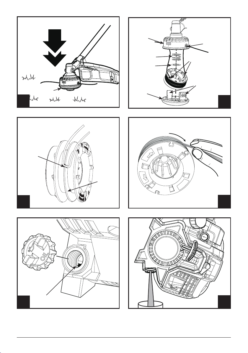
1. Remove the screw from the cutting head shield.
2. Insert the tab on the mount bracket into the slot in the
cutting head shield (Fig. 2).
3. Rotate the cutting head shield until the hole on the
mount bracket aligns with the screw hole on the cutting
head shield.
4. Insert the screw and tighten until the cutting head shield
is rmly in place.
CHANGING THE CUTTING HEAD
TO THE CUTTING BLADE
1. Unscrew and detach the cutting head.
2. Insert a tool so the mounting disc does not move. Install
the blade, washer, concave to be upwards, and the
oating disc (Fig. 3).
NOTE:
The pit side of washer must be contacted with the blade.
3. Screw down the locknut and tighten it counterclockwise
by the socket spanner.
4. Remove the socket spanner and the wrench and check
for freedom of motion of the blade.
CHANGING THE CUTTING BLADE
TO THE CUTTING HEAD
1. Insert a tool so the mounting disc doesn't move.
2. Loosen the looknut and remove the oating disc,
washer and the cutting blade.
3. Attach the cutting head to the mounting disc (Fig.4).
3. Check for secure installation.
INSTALLING THE HANDLE
1. Align and screw upper xed cover and the handle
support.
2. Lock two screws between lower xed cover and handle
support until the tube is are rmly in place (Fig. 5).
INSTALLING/REMOVING THE
LOWER SHAFT ATTACHMENT
In addition to the supplied line trimmer lower shaft, the
coupler on the upper shaft enables the use of various other
lower shaft attachments, available for separate purchase.
WARNING:
Before using any attachment, read and
understand the manual that came with the
attachment. Follow all safety information
contained within.To avoid serious personal injury
and damage to the unit, shut the unit off before
removing or installing an attachment.
To intsall:
1. Set the unit on a at, level surface.
2. Loosen the coupler knob (Fig. 6).
3. Align the locating button on the lower shaft with the
locating hole of the coupler (Fig. 7).
4. Then insert the lower shaft (Fig. 8).
5. Pull the lower shaft to check if it is frimly in place.
6. Tighten the knob for securing (Fig. 6).
To remove:
1. Set the unit on a at, level surface.
2. Loosen the coupler knob.
3. Press and hold the release button.
4. Pull the lower shaft attachment straight out of the
coupler.

17 - EN
WWW.SENIXTOOLS.COM
INSTALL THE HARNESS
The harness with quick release function can be hooked
on the shaft. You can wear it according to your using
preference.
OIL AND FUEL
ADDING OIL: INITIAL USE
Use a high-quality SAE 10W-30 weight oil. DO NOT use
dirty oil. Failure to use clean oil of the correct type can
cause premature engine wear and failure.
Attempting to start the engine before it has been properly
lled with lubricant will result in equipment failure not
covered by the warranty.
WARNING:
OVERFILLING THE CRANKCASE MAY
CAUSE excessive smoke, engine damage and
SERIOUS PERSONAL INJURY. Check the oil
level before each use.
NOTE:
This unit is shipped without oil in its crankcase but comes
with a 2.03 uid oz. (60 ml) container of oil seperately. Oil
must be added before starting the unit. Never add oil to the
fuel tank. This unit has a four-cycle engine. DO NOT mix oil
with gasoline.
1. Set the unit on a at, level surface.
2. Unscrew the oil ll plug (Fig. 9).
3. Pour the entire container of oil into the oil ll hole. Do
not overll. Refer to "CHECKING THE OIL LEVEL".
4. Wipe up any oil that may have spilled.
5. Reinstall the oil ll plug. Make sure the O-ring is in place
on the oil ll plug (Fig. 9).
FUELING THE UNIT
Gasoline and its vapors are highly ammable and
explosive. To prevent serious personal injury and property
damage during fueling, instructions listed below have to be
followed.
• Always wear safety protections to avoid injury.
• Add fuel in a clean, well-ventilated outdoor area and keep
sparks and open ames at a distance from the area.
• Always stop the engine and allow it to cool before lling
the fuel tank.
• Spilled fuel around the tank opening should be
immediately wiped off.
• Do not start the engine until fuel vapors dissipate.
• Do not smoke while fueling.
1. Position the unit with the fuel cap facing up.
2. Slowly remove the fuel cap. Handle it with care in case
of spray.
3. Place the fuel container spout into the fuel tank fill
hole and fill the tank. Stop when you see that the level
reaches the base of the tank spout (Fig. 10). Do not
overfill the tank.
4. Wipe up any fuel that may have spilled.
5. Reinstall the fuel cap.
6. Move the unit at least 30 ft. (9.1 m) from the fuel
container and the fueling site before starting the engine.
NOTE:
This unit has a four-cycle engine. DO NOT mix oil with
gasoline. The use of old fuel is the most common cause
of performance problems. Use only fresh, clean unleaded
gasoline.
DEFINITION OF BLENDED FUELS
Today’s fuels are often a blend of gasoline and oxygenates
such as ethanol, methanol or MTBE (ether). Alcohol-
blended fuel ab- sorbs water. As little as 1% water in the
fuel can make fuel and oil separate, forming acids when
stored. ALWAYS use fresh fuel (less than 30 days old) with
less than 10% ethanol.
NOTE:
Dispose of old fuel according to federal, state and local
regulations.
USING BLENDED FUELS
If using a blended fuel:
• Always use fresh unleaded gasoline
• Use the fuel additive STA-BIL® or an equivalent
WARNING:
DO NOT USE E85 or E15 FUEL IN THIS UNIT.
It has been proven that fuel containing greater
than 10% ethanol will likely damage this engine
and void the warranty.
USING FUEL ADDITIVES
Use a fuel additive, such as STA-BIL Fuel Stabilizer or an
equivalent, to inhibit corrosion and minimize gum deposits.
Add 0.8 oz. (23 ml) of fuel additive per gallon of fuel,
according to the instructions on the container. NEVER add
fuel additives directly to the unit’s fuel tank.

EN - 18 WWW.SENIXTOOLS.COM
OPERATION
WARNING:
Inspect unit before each start. Replace
damaged parts. Check for fuel leaks. Make sure
all fasteners are in place and secure. Replace
cutting attachment parts that are cracked,
chipped, or damaged in any way. Make sure
the cutting attachment is properly installed and
securely fastened and the cutting attachment
shield is properly attached.
STARTING INSTRUCTIONS
1. Check the oil level befor start.
2. Fill the fuel tank. Refer to "FUELING THE UNIT".
NOTE:
There is no need to turn the unit on. The On/Off switch is in
the On position at all times (Fig. 11).
3. Slowly press and release the primer bulb 10 times
(Fig. 12).
4. Push the choke button in until it clicks (Fig. 13).
5. Crouch in the starting position.To avoid serious injury,
the operator and the unit must be in a stable position
when pulling the starter rope (Fig. 14).
6. Pull the starter rope with a controlled and steady motion
5 times until you can hear the deagration of engine
(Fig. 12).
7. Press throttle control and throttle lockout at same time
to keep choke open (Fig. 11).
8. Pull the starter rope again to start the product. Allow the
engine to warm up for 30 to 60 seconds at idle speed
before increasing cutting speed.
9. When the product starts, press and hold throttle lockout
and squeeze the throttle lever to increase trimmer
cutting speed. The further you squeeze the throttle
control, the more the cutting speed will increase
(Fig. 11).
NOTE:
To prevent the throttle control from being squeezed
accidentally, this unit has a throttle lockout. The throttle
control cannot be squeezed unless the throttle lockout is
also engaged.
STOPPING INSTRUCTIONS
1. Release the throttle control and allow the engine to idle.
2. Press and hold the On/Off switch in the Off position until
the engine comes to a complete stop (Fig. 11). Make
sure the cutting attachment has stopped before the unit
is set down.
HOLDING THE UNIT
• Stand in the operating position. Stand up straight. Do not
bend over.
• Keep feet apart and rmly planted.
• Hold the handle withone hand while another on the
throttle grip.
• Hold the unit at waist level.
• Position the cutting head a few inches above the ground.
• Do not over-reach; Keep all parts of your body away from
the rotating cutting attachment and hot surfaces.
• To direct clippings away from you, whenever possible
swing the trimmer in a left to right cutting motion.
DECORATIVE TRIMMING
When trimming around trees, posts, fences, etc., rotate the
whole unit so that the cutting head is at a 30° angle to the
ground (Fig. 15).
ADJUSTING THE TRIMMING LINE
This unit is equipped with a bump head. Trimming line can
be released from the cutting head without stopping the
engine. To release more line, lightly tap the bump knob on
the ground while operating the unit at high speed (Fig. 16).
For best results, tap the bump knob on bare ground or hard
soil. Attempting to release line in tall grass may stall the
engine.
NOTE:
Do not rest the cutting head on the ground while the unit is
running. Each time the bump knob is tapped, about 1 inch
(25.4 mm) of trimming line is released.
Always keep the trimming line fully extended. Line release
becomes more difcult when the cutting line gets shorter.
WARNING:
Do not remove or alter the line cutting blade
assembly. Excessive line length will make the
unit overheat. This may lead to serious personal
injury or damage to the unit.

19 - EN
WWW.SENIXTOOLS.COM
Maintaining the Trimming Line
Hard surfaces, such as sidewalks, can cause the trimming
line to wear down quickly or break.
• Frequently check the trimming line length. Replace the
trimming line as needed. Refer to Replacing the Trimming
Line.
• Do not force the unit. Make shallow cuts in as many
passes as are necessary to achieve the desired depth.
Cut at a slow, even pace.
CUTTING TIPS
• Always wear eye protection with side shields marked to
comply with ANSI Z87.1, along with hearing protection.
Failure to do so could result in objects being thrown into
your eyes and other possible serious injuries.
• Operate this unit only in a well-ventilated outdoor area.
Carbon monoxide exhaust fumes can be lethal in a
conned area. Do not operate the unit inside a closed
environment, such as a room or building; breathing
carbon monoxide from exhaust fumes can kill.
• Clear the area to be cut before each use. Remove all
objects such as rocks, broken glass, nails, wire, or string
which can be thrown or become entangled in the cutting
attachment. Clear the area of children, bystanders, and
pets outside a 50 ft (15 m) radius.
• Avoid hot surfaces by always keeping the tool away from
your body.
• Cut all grass from top to down. This will prevent grass
from wrapping around the shaft housing and string head
which could cause damage from overheating.
• The preferred direction of trimmer operation is from left
to right .
• If grass becomes wrapped around the string head, stop
the engine, disconnect the spark plug wire, and remove
the grass.
• Use the tip of line to trim grass; do not force string head
into uncut grass.
• Avoid trees, owers, stones, walls and other objects which
can cause the line to break.
• Check and feed the line regularly to maintain full cutting
width and performance.
• Operation of this equipment could create sparks that
can start res around dry vegetation. A spark arrestor
may be required. The operator should contact local re
agencies for laws or regulations relating to re prevention
requirements.
TIPS FOR BEST RESULTS
• To direct clippings away from the operator, tilt the cutting
head slightly down to the right; whenever possible swing
the trimmer in a left to right cutting motion.
• Do not trim wet grass or weeds.
Some line breakage will occur from:
• Entanglement with foreign matter
• Normal line fatigue
• Attempting to cut thick vegetation
• Forcing the line into objects such as walls or fence posts
MAINTENANCE
To avoid serious personal injury, always stop the engine
and allow it to cool before cleaning or maintaining the unit.
Never perform cleaning or maintenance while the unit is
running. Disconnect the spark plug wire to prevent the unit
from starting accidentally.
Wear protective clothing and observe all safety instructions
to prevent serious personal injury.
Do not use any attachments or accessories not
recommended by the manufacturer of this product. Never
use metal-reinforced line, wire, chain or rope. These can
break off and become dangerous projectiles. Only use the
trimming line described in the specications section.Other
types of trimming line may cause the unit to overheat or fail.
REPLACING THE SPOOL
1. Push in the tabs on the side of the spool retainer and
pull to remove (Fig. 17).
2. Install the spring, washer, and rewound spool, making
sure that the lines are captured in the holding slots on
the new spool.
NOTE:
Make sure that the ends of the lines extend approximately
6 in. (152 mm).
3. Install the new spool so that the line ends align with the
eyelets in the cutting head, and thread the line ends
through the eyelets.
4. Pull the lines extending from the cutting head so that the
strings release from the slots in the spool.
5. Install the spool retainer by pressing the tabs into the
slots and pushing down on the spool until the spool
retainer clicks into place (Fig. 17).
REPLACING THE TRIMMING LINE
1. Remove the spool from the cutting head.
2. Remove any old line from the spool. Use a clean cloth
to clean the surface of the cutting head.
3. Cut a 15 ft. (4.5 m) length of 0.095 in. (2.4 mm) diameter
trimming line.
4. Bend the line at the midpoint and insert the bend into
the holding slot on the spool (Fig. 18).

EN - 20 WWW.SENIXTOOLS.COM
5. Wrap the line evenly and rmly around the spool (Fig.
19).
6. Position the lines in the spool holding slots (Fig. 18).
7. Install the spool in the cutting head. See "REPLACING
THE SPOOL".
NOTE:
Use only exible, nonmetallic line recommended by the
manufacturer. Never use, for example, wire or wire-rope,
which can break off and become a dangerous projectile.
MAINTENANCE SCHEDULE
Perform these required maintenance procedures at the
frequency stated in the table. These procedures should
also be a part of any seasonal tune-up. Some maintenance
procedures may require special tools or skills. If you are
unsure about these procedures, take the unit to a qualied
service dealer.
NOTE:
Maintenance, replacement, or repair of the emission control
devices and system may be performed by a qualied
service dealer.
NOTE:
Please read the California/EPA statement that came with
the unit for a complete listing of terms and coverage for
the emissions control devices, such as the spark arrestor,
mufer, carburetor, etc.
FREQUENCY MAINTENANCE REQUIRED
Every 10 hours • Clean the air lter. Refer to
"
MAINTAINING THE AIR FILTER".
Every 6 hours • Change the oil. Refer to "CHANGING
THE OIL".
After the rst 10
hours and at 38
hours
• Have the rocker arm clearance
checked by a qualied service
dealer.
• Check the spark plug condition and
gap. Refer to"MAINTAINING THE
SPARK PLUG".
CHECKING THE OIL LEVEL
Check the oil level before each use. The importance of
maintaining the proper oil level cannot be overemphasized.
Failure to keep the engine level may result in a faulty oil
level reading.If the oil level is too high, tip the unit and drain
the excess oil into an appropriate container.
DO NOT overll the oil level. Overlling will result in too
much oil in the engine crankcase, and may cause smoke or
fumes that can injure the user.
Inspecting the Oil Level
1. Stop the engine and allow it to cool.
2. Set the unit on a at, level surface, such as a workbench
or table. The cutting head shield should hang over the
edge so that the engine is level.
3. Unscrew the oil ll plug. The oil level should be visible
on the rst thread of the oil reservior (Fig. 20). If the oil
level is too low, add oil. Refer to "ADDING OIL".
Adding Oil
1. Clean the area around the oil ll plug to prevent debris
from entering the oil ll hole.
2. Unscrew the oil ll plug.
3. Add oil to the oil ll hole until the oil level is visible on the
rst thread of the oil reservoir (Fig. 20).
4. Wipe up any oil that may have spilled.
5. Make sure the O-ring is in place on the oil ll plug.
6. Reinstall the oil ll plug.
Changing The Oil
Old engine oil is considered special waste and has to be
disposed according to your local environment protection
regulation. Do not pour the oil into a garbage can, sewer,
soil etc.Dispose of the old oil according to federal, state and
local regulations.
Change the oil while the engine is still warm. The oil will ow
freely and carry away more impurities.
1. Clean the area around the oil ll plug to prevent debris
from entering the oil ll hole.
2. Unscrew the oil ll plug.
3. Tip the unit vertically to pour the oil out of the oil ll
hole and into a container (Fig. 21). Allow ample time for
complete drainage.
4. Wipe up any oil that may have spilled.
5. Pour 2.03 .oz. (60 ml) of SAE 10W-30 oil into the oil
ll hole.
6. Wipe up any oil that may have spilled.
7. Make sure the O-ring is in place on the oil ll plug.
8. Reinstall the oil ll plug.
MAINTAINING THE AIR FILTER
Failure to maintain the air lter can result in poor
performance or can cause permanent damage to the
engine.
Table of contents
Languages:
Other Senix Trimmer manuals

Senix
Senix HTX2-M User manual

Senix
Senix GTSX5-M-0 User manual

Senix
Senix HTE3.8-L User manual

Senix
Senix HT4QL-L User manual

Senix
Senix GTC4QL-L User manual

Senix
Senix HTPX2-M User manual

Senix
Senix HTX5-M User manual

Senix
Senix GTE2.5-L-EU User manual

Senix
Senix GTX2-M User manual

Senix
Senix GTS4QL-M2 User manual


