Sens DC PowerCab 120 Owner's manual

SENS®DC PowerCab™120
Installation, Operation, & Maintenance Manual

8/24/2017 2 755-00129 R04
Stored Energy Systems Packaged By:
1840 Industrial Circle C&C Power, Inc.
Longmont, Co 80501 395 Mission Street
www.sens-usa.com Carol Stream, IL 60188
Technical Support:
Phone: (303) 678-7500 or (800) 742-2326
Email: service@sens-usa.com
SENS, the SENS logo and PowerCab are trademarks of Stored Energy Systems LLC.

8/24/2017 3 755-00129 R04
TABLE OF CONTENTS
1. Important Information About This Manual................................................................................. 4
1.1 Manual Symbols.................................................................................................................... 4
2. Introduction................................................................................................................................. 5
3. Safety Precautions....................................................................................................................... 6
4. Inspection Upon Receipt of Goods.............................................................................................. 8
4.1 General .................................................................................................................................. 8
4.2 Visible Damage..................................................................................................................... 8
4.3 Concealed Damage................................................................................................................ 8
4.4 Return of Damaged Goods.................................................................................................... 8
5. System Overview ........................................................................................................................ 9
6. System Specifications................................................................................................................ 10
6.1 Batteries............................................................................................................................... 10
6.2 System Grounding............................................................................................................... 10
6.3 AC Input.............................................................................................................................. 10
6.4 DC Output ........................................................................................................................... 10
6.5 Optional AC Output ............................................................................................................ 11
6.6 Optional LVD...................................................................................................................... 11
6.7 General Specifications......................................................................................................... 11
7. Installation................................................................................................................................. 13
7.1 Preparation........................................................................................................................... 13
7.1.1 Equipment Inspection................................................................................................... 13
7.1.2 Necessary Equipment and Tools .................................................................................. 13
7.1.3 Installation Safety Precautions ..................................................................................... 13
7.2 Installation Steps ................................................................................................................. 13
7.2.1 Equipment Location ..................................................................................................... 13
7.2.2 Equipment Mounting.................................................................................................... 14
7.2.3 Equipment Grounding.................................................................................................. 14
7.2.4 AC/DC Connections..................................................................................................... 14
7.2.5 System Operation ......................................................................................................... 15
8. System Maintenance.................................................................................................................. 16
8.1 Battery Replacement ........................................................................................................... 16
9. Reference Materials................................................................................................................... 18
10. Warranty.................................................................................................................................. 23

SENS®DC PowerCab™120
8/24/2017 4 755-00129 R04
1.IMPORTANT INFORMATION ABOUT THIS MANUAL
SAVE THESE INSTRUCTIONS! This manual contains important information that is needed
during the installation and maintenance of the system.
1.1 MANUAL SYMBOLS
Warning / Caution:
Indicates information provided to protect the user against personal injury, safety
hazards and/or possible equipment damage.
Important:
Indicates information provided as an installation or operating instruction or tip as
well as general important installation and system information.

SENS®DC PowerCab™120
8/24/2017 5 755-00129 R04
2. INTRODUCTION
Stored Energy Systems (SENS®) would like to thank you for choosing SENS product for your
power and back-up equipment needs. We know there are a lot of choices in the industry, and we
appreciate the opportunity to supply our customers with the highest quality power products
manufactured in the United States.
All SENS products are built to the highest industry standards and are Hi Pot tested to UL standards
prior to shipment. All standard configurations are C-UL listed.
Sales support for existing or future equipment needs are provided by our technical sales staff. For
all technical, sales, and service related questions please call our office line at 303-678-7500 and
you will be directed to the appropriate individual to answer your questions.
After normal working hoursplease leave a detailed message, withyour phone number, on our voice
mail system and a qualified representative will contact you as quickly as possible.
Stored Energy Systems Packaged By:
1840 Industrial Circle C&C Power, Inc.
Longmont, Co 80501 395 Mission Street
www.sens-usa.com Carol Stream, IL 60188
Technical and Sales Support:
Phone: (303) 678-7500 or (800) 742-2326
Email: service@sens-usa.com
SENS®DC PowerCab™120
8/24/2017 6 755-00129 R04
3. SAFETY PRECAUTIONS
Before installing or maintaining this system, it is extremely important to read this
manual and be surethat all systemdrawings and schematics are reviewed and clearly
understood. If there are any questions concerning this manual or any of the
installation or maintenance procedures and/or requirements please contact a C&C
Power representative before proceeding.
When installing this power system, follow all applicable federal, state and local
regulations as well as industry guidelines to insure proper system installation.
Only qualified electricians or DC power technicians should attempt to install or
service this equipment.
System installation and maintenance should always be performed with heavily
insulated tools. It is also recommended to wear rubber gloves, boots, and use
insulating mats to stand on when working on this equipment.
Always wear eye protection when installing or maintaining batteries and/or power
equipment.
Do not attempt to unpack or move the battery cabinet without assistance. Use
appropriate handling equipment rated to bear the weight and bulk of the battery
cabinet, such as freight elevators, pallet jacks and forklifts. (Fully extend forks under
load. Spread forks to maximum possible width under load. Lift cabinet from bottom
only. Wear safety shoes.)
Do not smoke or present open flames near any battery system.
For the safety of others, never leave an open cabinet or panel unattended.
To reduce the risk of fire, replace fuses with the same type and rating of fuses
supplied with the system.
SENS®DC PowerCab™120
8/24/2017 7 755-00129 R04
DC Power and Batteries can be very dangerous and have extremely high short circuit
current. Electrical shock, severe burns, fire or death can result from a system short.
To avoid personal injury including electrical shock, severe burns and possible death,
all jewelry including bracelets, rings and watches mustbe removed prior to installing
or servicing this system.
Do not open or mutilate batteries. Opened or severely damaged batteries can release
toxic electrolyte which is harmful to the skin and eyes.
Never lay loose cables, metal parts or tools on top of batteries.
Under certain conditions, batteries can vent potentially explosive gas (hydrogen).
Never enclose batteries or battery cabinets in a sealed room.

SENS®DC PowerCab™120
8/24/2017 8 755-00129 R04
4. INSPECTION UPON RECEIPT OF GOODS
4.1 GENERAL
Special precautions and care have been taken to ensure the system arrives safe and undamaged.
However, upon receipt, you should inspect the entire shipment, including the crate and any boxes
for evidence of damage that may have occurred during transit.
4.2 VISIBLE DAMAGE
It is the responsibility of the person receiving the shipment to inventory and fully inspect all
materials against the bill of lading or weigh bill IMMEDIATELY while the carrier representative
is still present. Insure that all items are accounted for, including number of skids and quantity of
boxes. Also note any visible external damage that may have occurred during transit. Make all
applicable notations on the delivery receipt before signing and file a damage report with the carrier.
4.3 CONCEALED DAMAGE
Within 3 to 30 days of receipt (depending on courier), unpack the system and check for any
concealed damage. Check the materials received against the detailed packing list to verify the
quantity and the condition as complete and satisfactory.
Note any damage to the internal packaging, then request an inspection by the carrier and file a
concealed damage claim. If there is a material shortage, contact a representative at SENS to file a
claim.
Please contact your shipping company for all shipping damage.
C&C Power is not responsible for any shipping damage.
4.4 RETURN OF DAMAGED GOODS
Should equipment be damaged and require return, contact SENS Technical Support. A
representative will provide instructions along with an RMA number to expedite the return.
A RMA number must be obtained before returning equipment to Sens or C&C Power, Inc.

SENS®DC PowerCab™120
8/24/2017 9 755-00129 R04
5. SYSTEM OVERVIEW
The DC PowerCab 120 is a non-stop DC power system designed to deliver uninterruptible DC
power to critical loads. PowerCab includes a DC power supply/charger, storage battery string, and
DC distribution to load center.
In addition to the charger, battery, distribution panel and cabinet, PowerCab can be optionally
equipped with:
•Additional DC distribution
•Low voltage disconnect (to prevent battery from over-discharge)
•Top-Lift Bracket
•Multiple DC to AC inverter options
The DC PowerCab system is fully factory assembled and is ready to install upon delivery.
SENS®DC PowerCab™120
8/24/2017 10 755-00129 R04
6.SYSTEM SPECIFICATIONS
6.1 BATTERIES
Type: Valve Regulated Lead Acid (VRLA), sealed, non-spillable
Amp-Hour Options: 100 AH, 150AH, 170AH or 200AH
Voltage: 12 VDC Nominal
6.2 SYSTEM GROUNDING
Cabinet Safety Ground: Each cabinet is supplied with a mechanical ground lug that accepts bare
wire from #2/0 AWG to #14 AWG.
Torque: 375 in-lbs
Wire Size and Type: Ground wire should be sized per NEC and/or all applicable national and
local codes.
6.3 AC INPUT
The AC input to the charger (see Figure 1 for location) can be:
208 VAC 60 Hz, 1ф
230 VAC 50/60 Hz, 1ф
240 VAC 60 Hz, 1ф
115-120/208/230-240 VAC 60 Hz, 1ф
115-120/208/230-240 VAC, 50/60 Hz, 1ф
400 VAC 50/60 Hz, 1ф
480 VAC 60 Hz, 1ф
6.4 DC OUTPUT
DC Output Voltage Options include:
•24-volt nominal (12 cells lead-acid)
•48-volt nominal (24 cells lead-acid)
•120-volt nominal (60 cells lead-acid)
•240-volt nominal (120 cells lead-acid)
Charger Output Current Options include:
•6 Amps (15A charger to panelboard breaker)
•12 Amps (15A charger to panelboard breaker)
•16 Amps (20A charger to panelboard breaker)
•25 Amps (35A charger to panelboard breaker)
•35 Amps (45A charger to panelboard breaker)
•50 Amps (70A charger to panelboard breaker)
Only cabinets with Flame Retardant Batteries are suitable for computer room use.
All system ground wires should be derived from the main building ground source.

SENS®DC PowerCab™120
8/24/2017 11 755-00129 R04
•75 Amps (100A charger to panelboard breaker)
•100 Amps (125A charger to accessory breaker)
•150 Amps (200A charger to accessory breaker)
DC Load Center: Panelboard, 100A, 2-pole battery main breaker, 2-pole charger-feed breaker,
plus 12 each 2-pole load breaker positions.
Wire Size and Type: Per NEC and/or all applicable national and local codes.
6.5 OPTIONAL AC OUTPUT
•600 Watt Inverter, 120VAC, 60Hz
•600 Watt Inverter, 230VAC, 50Hz
•1000 Watt Inverter, 120VAC, 60Hz
•1000 Watt Inverter, 230VAC, 50Hz
•1100 Watt Inverter, 120VAC, 60Hz
•1100 Watt Inverter, 230VAC, 50Hz
•2000 Watt Inverter, 120VAC, 60Hz
•2000 Watt Inverter, 230VAC, 50Hz
•3000 Watt Inverter, 120VAC, 60Hz
•3000 Watt Inverter, 230VAC, 50Hz
AC output option consumes one 2-pole load breaker position.
Wire Size and Type: Per NEC and/or all applicable national and local codes.
6.6 OPTIONAL LVD
When AC power fails,the systems batteries will discharge in order to provide the necessary backup
power to the load. If the DC PowerCab 120 is equipped with the Low Voltage Disconnect (LVD)
feature, the system load will be automatically disconnected at the customer adjustable LVD
disconnect voltage setting. This will prevent the batteries from being discharged to unsafe levels.
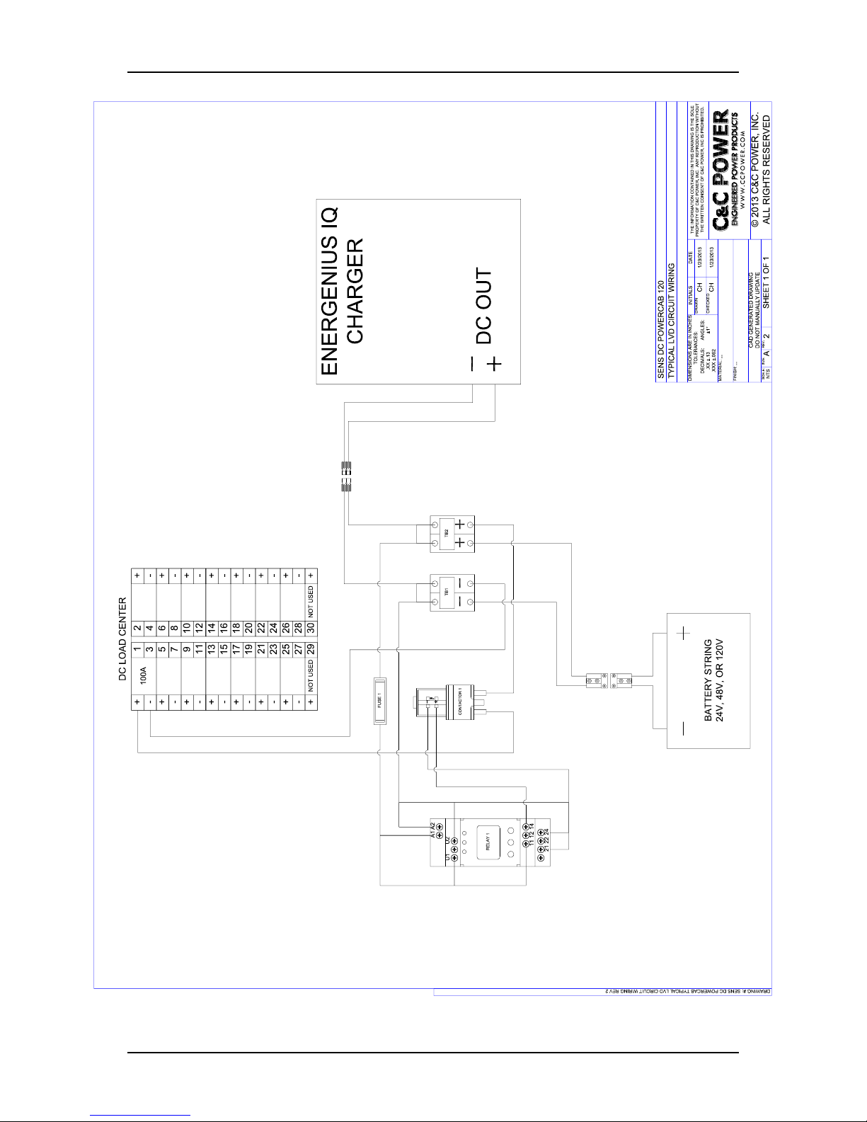
A Bender VME420 type Digital Voltage Monitor Relay is used to control the contactor in the LVD
circuit. The LVD circuit, with the Monitor Relay imbedded, wiring connections to the DC load
center and the Charger is shown in Figure 2/Section 9. The activation and factory settings of the
LVD Voltage Relay are shown in Figure 3/Section 9 for a 120 VDC system, Figure 4/Section 9 for
a 48 VDC system and Figure 5/Section 9 for a 24 VDC system.
6.7 GENERAL SPECIFICATIONS
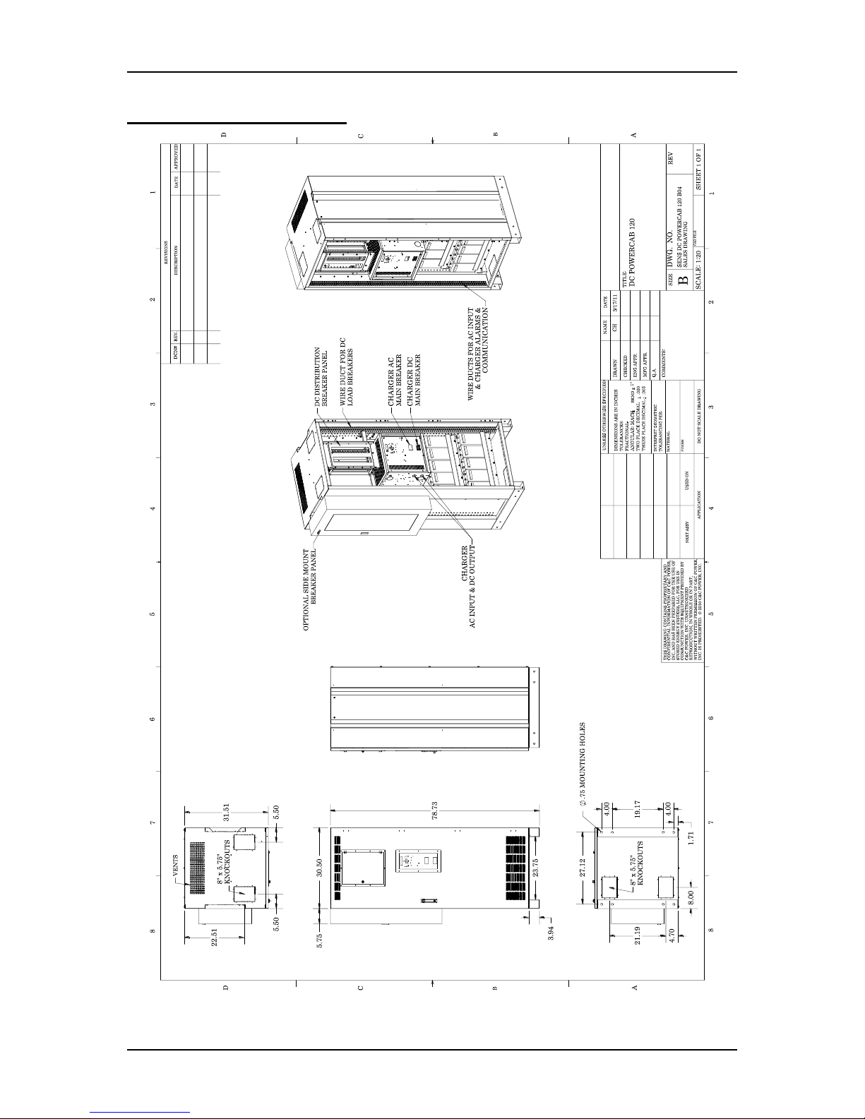
Cabinet Size: 30.5”W x 31.5”D x 78.7”H
Typical Weights:
Empty Cabinet (approximately): 450 lbs
Complete System Weight can be found on the individual cabinet drawing that is mounted to the
inside of the door.
Wire should be sized for a maximum voltage drop of 0.5 volt.
SENS®DC PowerCab™120
8/24/2017 12 755-00129 R04
Operating Temperature: 20°C to 25°C (68°F to 77°F) recommended for optimum battery
performance.
Ventilation: Ventilation holes located in the front, rear, and top of the cabinet. Clearance around
the equipment should be as suggested by NEC and/or all applicable national and local codes. The
battery cabinet does not require rear access or rear clearance.
Under certain conditions, batteries can vent potentially explosive gas (hydrogen).
Never enclose batteries or battery cabinets in a sealed room.
Batteries should be stored no longer than three months at 25°C (77°F) or lower
before recharging. Exceeding the recommended ambient storage temperature may
cause damage to the batteries.

SENS®DC PowerCab™120
8/24/2017 13 755-00129 R04
7. INSTALLATION
7.1 PREPARATION
7.1.1 EQUIPMENT INSPECTION
Remove the equipment from the packaging material and inspect for any shipping damage that
may have been overlooked upon receipt of goods. Verify that the system includes all necessary
hardware for installation.
7.1.2 NECESSARY EQUIPMENT AND TOOLS
oHeavily insulated assortment of hand tools
oDigital voltmeter
7.1.3 INSTALLATION SAFETY PRECAUTIONS
7.2 INSTALLATION STEPS
7.2.1 EQUIPMENT LOCATION
Prior to installation, verify floor loading requirements (see weights in Section 6.7) and all
applicable codes pertaining to the related equipment. Environmental conditions should also be
reviewed. Battery systems require an area with proper ventilation and cooling. An ambient
temperature between 20°C to 25°C (68°F to 77°F) is recommended for optimum battery life and
performance. Clearance around the equipment should be as suggested by NEC and/or all
applicable national and local codes. The battery cabinet does not require rear access or rear
clearance.
Before proceeding with system installation, be sure to review and understand all of
the SAFETY PRECAUTIONS in this manual!
DC VOLTAGE WARNING!
Hazardous DC voltages are present in the system. This hazard will always be
present in a battery system including when it is offline. Accidental short circuit
of the positive and negative terminal will cause tremendous currents to flow
resulting in electrical shock, severe burns, fire and possible death! Use extreme
caution when installing and maintaining the system!
Before installing or maintaining this system, it is extremely important to read this
manual and be surethat all systemdrawings and schematics are reviewed and clearly
understood. If there are any questions concerning this manual or any of the
installation or maintenance procedures and/or requirements please contact a C&C
Power representative before proceeding.
Under certain conditions, batteries can vent potentially explosive gas (hydrogen).
Never enclose batteries or battery cabinets in a sealed room. Follow international
(IFC 608), state, and local codes for ventilation requirements.
SENS®DC PowerCab™120
8/24/2017 14 755-00129 R04
7.2.2 EQUIPMENT MOUNTING
1. The SENS DC PowerCab 120 cabinet is equipped with pallet jack and/or forklift access
openings in the front and rear of the cabinet. Move the equipment into the desired location
and set into place.
2. With the cabinet in the desired location, mark the location of four mounting holes found at
the bottom of the cabinet legs. Two sets of mount holes are provided so that mount hardware
can be offset in multi cabinet installations.
3. Move the cabinet out of the way and drill holes for the mounting hardware that will be used.
4. Move the cabinet back into place, align the holes, and tighten the hardware.
5. Should any drilling be performed on this equipment, make sure all exposed batteries and
connections are completely covered using insulated type mats.
7.2.3 EQUIPMENT GROUNDING
Terminate a cabinet ground wire from the main building ground source to the supplied #2/0 AWG
- #14AWG mechanical lug located on the bottom panel of the cabinet in the front right-hand corner.
Wire should be sized per NEC and/or all applicable national and local codes.
7.2.4 AC/DC CONNECTIONS
Do not attempt to unpack or move the battery cabinet without assistance. Use
appropriate handling equipment rated to bear the weight and bulk of the battery
cabinet, such as freight elevators, pallet jacks and forklifts. (Fully extend forks under
load. Spread forks to maximum possible width under load. Lift cabinet from bottom
only. Wear safety shoes.)
All system ground wires should be derived from the main building ground source.
For multi cabinet systems, each cabinet needs to have a designated cabinet ground
wire derived from the main building ground source.
Review the attached to the cabinet System Drawings and Schematics for model
specific information on DC output connections to the panelboard.
Wire should be sized for a maximum voltage drop of 0.5 volt.
Verify that the Battery Main Breaker and the Charger Main Breaker on the
panelboard (see System Drawing/Schematic) are in the off/open position before
making any DC connections from the panelboard breakers to their respective loads.

SENS®DC PowerCab™120
8/24/2017 15 755-00129 R04
Open the front doors on the cabinet and check for any noticeable problems or damage that may
have occurred during shipment.
1. Review the attached system drawing/schematic located inside the cabinet doors to find the
location of the jumper that has been left off in the middle of the battery string for added safety
during installation and shipping. This jumper will be installed later.
2. Check and re-torque all internal battery connections, as shipping may have caused these
connections to come loose. Proper torque values are noted on the system schematic/drawing
and can also be found on most battery cases.
3. Refer to the Charger Operation Installation and Operation Manual for instructions for making
AC power connections to the charger. The AC input cables can ingress the cabinet from either
the top panel or the bottom panel by removing the appropriate panel knockout plate. The AC
input cables should be run in the wire ducts located on the left-side of the cabinet from the
cabinet ingress point to the connection point on the charger.
4. Without LVD Option: Verify that the battery string output and the charger DC output are
connected to the breakers on the panelboard specified in the system schematic/drawing.
Assure that thesetwo breakers are in the off/open position before making any DC connections
from the panelboard breakers to their respective loads.
With LVD Option: Referencing Figure 2/ Section 9, verify that the battery string output and
the charger DC output are connected as shown to the LVD circuit and the LVD circuit is
terminated to the proper breaker in the DC Load Center.
5. Review the supplied cabinet schematic/drawing for information on the size and location of
the DC distribution breakers on the panelboard. Route the DC output cables fromthe breakers
through the wire duct located on the right-side of the cabinet to the cabinet egress point on
the top of the cabinet (after removing the knockout plate) and connect to their respective
loads. All cables should be sized per NEC and any other local codes pertaining to this
equipment.
6. Connect the jumper that was left off during shipment and install as shown on the system
schematic. Torque connections properly.
7.2.5 SYSTEM OPERATION
Please refer to the Charger Operation Installation and Operation Manual included with the SENS
DC PowerCab 120 product for startup and operation information for the charger unit.
SENS®DC PowerCab™120
8/24/2017 16 755-00129 R04
8.SYSTEM MAINTENANCE
8.1 BATTERY REPLACEMENT
1. Prepare the new battery for installation. Verify that the battery is the same type and amp-hour
rating as the batteries that are in the system.
2. Using a digital voltmeter, measure the battery voltage to verify that it is 12.4 VDC or above.
3. Use a brass wire brush or abrasive pad to polish the battery terminals.
4. Apply no-ox type terminal grease to the battery terminals to avoid corrosion.
5. Disconnect the loads from the battery string by turning off/opening the Battery Main circuit
breaker on the panelboard.
6. Remove the centerjumper on the battery string to reduce the voltage. If replacing all batteries,
continue reducing the voltage by removing the inter-shelf jumper.
7. Disconnect the cables from the battery to be replaced.
8. Remove the bad battery.
Before proceeding with system maintenance, be sure to review and understand all of
the SAFETY PRECAUTIONS in this manual!
Verify that the Battery Main breaker on the panelboard and Charger AC Main
breaker (on the charger unit) are in the off/open position before servicing the system.
When batteries are replaced they must be properly installed paying special attention
to terminal polarity orientation! If wired incorrectly it will cause a short in the system
and can result in electrical shock, severe burns, fire and possible death! Be sure to
review the system schematics before terminating any battery cables.
Caution: Risk of explosion if batteries are replaced by an incorrect type.
Do not dispose of batteries in a fire. The batteries may explode. Contact your local
hazardous waste or recycling center for battery disposal requirements.
Do not discard batteries in the trash. This product contains sealed lead acid
batteries. Contact your local hazardous waste or recycling center for battery
disposal requirements.

SENS®DC PowerCab™120
8/24/2017 17 755-00129 R04
9. Put the new battery into place. Make sure new battery is installed properly regarding polarity
orientation. Use the supplied wiring schematic/ drawing found inside the battery cabinet door
to verify the cabinet wiring.
10. Reconnect the cables to battery and make sure the connections are properly torqued.
11. Reconnect any removed string jumpers and make sure the connections are properly torqued.
12. Check the battery string voltage at input side of the Battery Main circuit breaker.
13. Start the charger and reconnect the loads to the battery string by turning on/closing the circuit
breakers turned off in step 5.
SENS®DC PowerCab™120
8/24/2017 18 755-00129 R04
9. REFERENCE MATERIALS
Figure 1
SENS®DC PowerCab™120
8/24/2017 19 755-00129 R04
Figure 2

SENS®DC PowerCab™120
8/24/2017 20 755-00129 R04
SENS DC PowerCab LVD Voltage Relay Settings - 120 VDC Systems
Bender VME420-D-2 (043-00009)
The settings for the LVD Voltage Relay are listed in the table below:
Menu
Sub Menu
Menu Item
Activation
& Setting
Adjustable parameter
AL
(response
- values)
------->
<U
ON
(105V)
Undervoltage
>U
OFF
Overvoltage
U Hys
14%
Hysteresis < U / > U
< Hz
OFF
Underfrequency
> Hz
OFF
Overfrequency
Hz Hys
N/A
Hysteresis, frequency
out
(output
control)
------->
M
OFF
Fault memory
1
N.C.
Operating mode K1
2
N.C.
Operating mode K2
LEd
OFF
LED’s Signal relay in alarm state
r1 (K1:
(assignment
alarm
category)
1 Err
OFF
Device error at K1
r1 < U
ON
Undervoltage K1
r1 > U
OFF
Overvoltage K1
r1 < Hz
OFF
Underfrequency K1
r1 > Hz
OFF
Overfrequency K1
1 S.AL
OFF
Start with alarm during (t+t) on1
r2 (K2:
(assignment
alarm
category)
2 Err
OFF
Device error K2
r2 < U
ON
Undervoltage K2
r2 > U
OFF
Overvoltage K2
r2 < Hz
OFF
Underfrequency K2
r2 > Hz
OFF
Overfrequency K2
2 S.AL
OFF
Start with alarm during (t+t) on2
t
(timing
check)
------->
t on 1
0
Response delay K1
t on 2
0
Response delay K2
T
0
Starting delay
t off
0
Delay on release K1/K2
Set
(device
control)
------->
OFF
Parameter setting via password
FAC
-
Re-establish factory settings
PrE
-
Manual preset
SYS
-
Function blocked
InF
--------------->
-
Display hard/ software version
HiS
------->
Clr
-
History memory for the first alarm value, erasable
Figure 3
Table of contents
Popular UPS manuals by other brands

Elen
Elen B1 Series user manual

Vertiv
Vertiv Liebert GXT5-5000MVRT4UXLN Installer/user guide

GE
GE Uninterruptible Power Supply user manual

Pacific Power Source
Pacific Power Source 3060-UMS Operation manual

Eaton
Eaton Powerware 9395 installation instructions

Cineparts
Cineparts SRWpower LE User instructions


Tech Novitas
Tech Novitas venus flexi series user manual

OPTI-UPS
OPTI-UPS Line Interactive UPS Series PS1000B-RM Specifications

Para systems
Para systems ETR500 user manual

CyberPower
CyberPower BL1450U user manual

socomec
socomec Green Power 2.0 10 Installation and operating manual

Lowell
Lowell UPS9-1000 User & installation manual