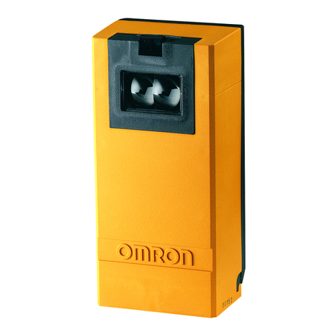
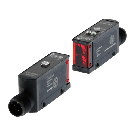
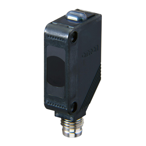
Omron EE-SX47 - User manual

Photomicro Sensors with Built-in Amplifier
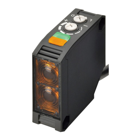
EE-SX670
EE-SX670-WR
EE-SX770
EE-SX910-R
Actual sizeBe sure to read page 27 before ordering.
Printed in Japan
0307-0.5M (0307) (C)
ALL DIMENSIONS SHOWN ARE IN MILLIMETERS.
To convert millimeters into inches, multiply by 0.03937. To convert grams into ounces, multiply by 0.03527.
Cat. No. E382-E1-01 In the interest of product improvement, specifications are subject to change without notice.
OMRON Corporation
Industrial Automation Company
Sensing Devices Division H.Q.
Industrial Sensors Division
Shiokoji Horikawa, Shimogyo-ku,
Kyoto, 600-8530 Japan
Tel: (81)75-344-7022/Fax: (81)75-344-7107
Regional Headquarters
OMRON EUROPE B.V.
Sensor Business Unit,
Carl-Benz-Str. 4, D-71154 Nufringen,
Germany
Tel: (49)7032-811-0/Fax: (49)7032-811-199
OMRON ELECTRONICS LLC
1 East Commerce Drive, Schaumburg,
IL 60173 U.S.A.
Tel: (1)847-843-7900/Fax: (1)847-843-8568
OMRON ASIA PACIFIC PTE. LTD.
438A Alexandra Road #05-05/08
Alexandra Technopark
Singapore 119967
Tel: (65)6835-3011/Fax: (65)6835-2711
OMRON (CHINA) CO., LTD.
Room 2211, Bank of China Tower,
200 Yin Cheng Road (M),
Shanghai, 200120 China
Tel: (86)21-5037-2222/Fax: (86)21-5037-2200
This document provides information mainly for selecting suitable models. Please read the Instruction sheet
carefully for information that the user must understand and accept before purchase, including information on
warranty, limitations of liability, and precautions.

A Complete Product Lineup
for the Perfect Selection
EE-SX
670-WR EE-SX
670
EE-SX
671-WR
EE-SX
671
EE-SX
672-WR
EE-SX
672
EE-SX
673-WR
EE-SX
673
EE-SX
674-WR
EE-SX
674
EE-SX
911-R
EE-SX
912-R
EE-SX
913-R
EE-SX
914-R
EE-SX
770
EE-SX
772
EE-SX
771
EE-SX
910-R
EE-SX
675-WR
EE-SX
675
EE-SX
676-WR
EE-SX
677
EE-SX
677-WR
EE-SX
676
S
t
a
n
d
a
r
d
E
E
-
S
X
4
7
/
6
7
S
e
r
i
e
s
T
h
i
n
E
E
-
S
X
7
7
/
8
7
s
e
r
i
e
s
C
o
m
p
a
c
t
E
E
-
S
X
9
1
S
e
r
i
e
s

4
Slot-type Photomicrosensor with connector or pre-wired models (Non-modulated)
*1
EE-SX47/67
Photomicrosensor with 50- to 100-mA
direct switching capacity for built-in
application.
■Series includes models that enable switching between
dark-ON and light-ON operation.
■Response frequency as high as 1 kHz.
■Easy operation monitoring with bright light indicator.
■Wide operating voltage range: 5 to 24 VDC
■Models in which the light indicator turns ON for dark-ON
operation are also available.
■A wide range of variations in eight different shapes.
■Flexible robot cable is provided as a standard feature. *2
*1. Only the EE-SX67 Series has pre-wired models.
*2. Pre-wired models only.
Be sure to read Safety Precautions on
page 8.
Ordering Information
Connector models
*3. These models can be used as Light-ON when the L terminal and positive (+) terminal are connected to each other. To use them as Dark-ON, do not connect these terminals
to each other. When used at light-ON, it is useful to select the connector EE-1001-1. The L terminal and positive (+) terminal of this connector are short-circuited in advance.
Appearance Sensing
method
Connect-
ing method
Sensing distance Output
configuration Indicator mode Model
NPN output PNP output
Through-
beam
type
(with slot)
Connector
(4 poles)
Dark-ON/Light-ON
(selectable) *3
Incident light EE-SX670 EE-SX670P
No incident light EE-SX670A EE-SX670R
Light-ON Incident light EE-SX470 EE-SX470P
Dark-ON/Light-ON
(selectable) *3
Incident light EE-SX671 EE-SX671P
No incident light EE-SX671A EE-SX671R
Light-ON Incident light EE-SX471 EE-SX471P
Dark-ON/Light-ON
(selectable) *3
Incident light EE-SX672 EE-SX672P
No incident light EE-SX672A EE-SX672R
Light-ON Incident light EE-SX472 EE-SX472P
Dark-ON/Light-ON
(selectable) *3
Incident light EE-SX673 EE-SX673P
No incident light EE-SX673A EE-SX673R
Light-ON Incident light EE-SX473 EE-SX473P
Dark-ON/Light-ON
(selectable) *3
Incident light EE-SX674 EE-SX674P
No incident light EE-SX674A EE-SX674R
Light-ON Incident light EE-SX474 EE-SX474P
Dark-ON/Light-ON
(selectable) *3Incident light EE-SX675 EE-SX675P
Dark-ON/Light-ON
(selectable) *3Incident light EE-SX676 EE-SX676P
Dark-ON/Light-ON
(selectable) *3Incident light EE-SX677 EE-SX677P
Infrared li
g
ht
Standard
5 mm
(slot width)
L
-s
h
ape
d
T-shaped
Close-
mounting
Close-
mounting
T-shaped,
slot center:
10 mm
F-shaped
R-shaped

EE-SX47/67
5
Pre-wired Models and Models with Junction Connectors
*
These models can be used as Light-ON when the L line and positive (+) line are connected to each other.
To use them as Dark-ON, do not connect these lines to each other.
Accessories for Models with Connectors (Order Separately)
Accessories for Models with Junction Connectors (Order Separately)
Appearance Sensing
method Sensing distance
Output
configura-
tion
Indicator
mode
Connecting
method
Model
NPN output PNP output
Through-
beam
type
(with slot)
Dark-ON/
Light-ON
(selectable) *
Incident
light
Pre-wired
models (1 m)
EE-SX670-WR EE-SX670P-WR
Models with junction
connectors (0.1 m)
EE-SX670-C1J-R EE-SX670P-C1J-R
Pre-wired
models (1 m)
EE-SX671-WR EE-SX671P-WR
Models with junction
connectors (0.1 m)
EE-SX671-C1J-R EE-SX671P-C1J-R
Pre-wired
models (1 m)
EE-SX672-WR EE-SX672P-WR
Models with junction
connectors (0.1 m)
EE-SX672-C1J-R EE-SX672P-C1J-R
Pre-wired
models (1 m)
EE-SX673-WR EE-SX673P-WR
Models with junction
connectors (0.1 m)
EE-SX673-C1J-R EE-SX673P-C1J-R
Pre-wired
models (1 m)
EE-SX674-WR EE-SX674P-WR
Models with junction
connectors (0.1 m)
EE-SX674-C1J-R EE-SX674P-C1J-R
Pre-wired
models (1 m)
EE-SX675-WR EE-SX675P-WR
Models with junction
connectors (0.1 m)
EE-SX675-C1J-R EE-SX675P-C1J-R
Pre-wired
models (1 m)
EE-SX676-WR EE-SX676P-WR
Models with junction
connectors (0.1 m)
EE-SX676-C1J-R EE-SX676P-C1J-R
Pre-wired
models (1 m)
EE-SX677-WR EE-SX677P-WR
Models with junction
connectors (0.1 m)
EE-SX677-C1J-R EE-SX677P-C1J-R
Infrared li
g
ht
Standard
5 mm
(slot width)
L
-s
h
ape
d
T-shaped,
slot center:
7 mm
Close-
mounting
Close-
mounting
T-shaped,
slot center:
10 mm
F-shaped
R-shaped
Type Cable
length Model Remarks
Connector EE-1001
EE-1001-1 L terminal and positive (+) terminal are already short-circuited.
EE-1009
Connector with Cable
1 m EE-1006
EE-1010
2 m EE-1006
EE-1010
Connector with Robot
Cable
1 m EE-1010-R
2 m EE-1010-R
Connector Hold-down Clip EE-1006A For EE-1006 only.
Type Cable
length Model Remarks
Connector with Robot Cable 2m EE-1016-R-1 For EE-SX67@-C1J-R.

6
EE-SX47/67
Ratings and Specifications
*1. The indicator is a GaP red LED (peak wavelength: 690 nm).
*2. The response frequency was measured by detecting the rotating disk
shown at the right.
Connector for the EE-SX67 with Junction Connector
Item
Type Standard L-shaped
T-shaped, slot
center: 7 mm
Close-mounting
T-shaped, slot
center: 10 mm
F-shaped R-shaped
NPN
mod-
els
Connector
EE-SX670
EE-SX670A
EE-SX470
EE-SX671
EE-SX671A
EE-SX471
EE-SX672
EE-SX672A
EE-SX472
EE-SX673
EE-SX673A
EE-SX473
EE-SX674
EE-SX674A
EE-SX474
EE-SX675 EE-SX676 EE-SX677
Pre-wired
models
EE-SX670-
WR
EE-SX671-
WR
EE-SX672-
WR
EE-SX673-
WR
EE-SX674-
WR
EE-SX675-
WR
EE-SX676-
WR
EE-SX677-
WR
Models with junc-
tion connectors
EE-SX670-
C1J-R
EE-SX671-
C1J-R
EE-SX672-
C1J-R
EE-SX673-
C1J-R
EE-SX674-
C1J-R
EE-SX675-
C1J-R
EE-SX676-
C1J-R
EE-SX677-
C1J-R
PNP
mod-
els
Connector
EE-SX670P
EE-SX670R
EE-SX470P
EE-SX671P
EE-SX671R
EE-SX471P
EE-SX672P
EE-SX672R
EE-SX472P
EE-SX673P
EE-SX673R
EE-SX473P
EE-SX674P
EE-SX674R
EE-SX474P
EE-SX675P EE-SX676P EE-SX677P
Pre-wired
models
EE-SX670P-
WR
EE-SX671P-
WR
EE-SX672P-
WR
EE-SX673P-
WR
EE-SX674P-
WR
EE-SX675P-
WR
EE-SX676P-
WR
EE-SX677P-
WR
Models with junc-
tion connectors
EE-SX670P-
C1J-R
EE-SX671P-
C1J-R
EE-SX672P-
C1J-R
EE-SX673P-
C1J-R
EE-SX674P-
C1J-R
EE-SX675P-
C1J-R
EE-SX676P-
C1J-R
EE-SX677P-
C1J-R
Sensing distance 5 mm (slot width)
Sensing object Opaque: 2 ×0.8 mm min.
Differential distance 0.025 mm
Light source GaAs infrared LED with a peak wavelength of 940 nm
Indicator *1Light indicator (red) (turns ON when light is interrupted for models with A or R suffix)
Supply voltage 5 to 24 VDC ±10%, ripple (p-p): 10% max.
Current consumption 35 mA max. (NPN models), 30 mA max. (PNP models)
Control output
NPN open collector: 5 to 24 VDC, 100 mA max.
100 mA load current with a residual voltage of 0.8 V max.
40 mA load current with a residual voltage of 0.4 V max.
PNP open collector: 5 to 24 VDC, 50 mA max.
50 mA load current with a residual voltage of 1.3 V max.
Response frequency
*
2
1 kHz min. (3 kHz average)
Ambient illumination 1,000 lx max. with fluorescent light on the surface of the receiver.
Ambient temperature range
Operating: −25 to +55°C, Storage: −30 to +80°C
Ambient humidity range Operating: 5% to 85%, Storage: 5% to 95%
Vibration resistance Destruction: 20 to 2,000 Hz (peak acceleration: 100 m/s2)
1.5-mm double amplitude for 2 h (4-min periods) each in X, Y, and Z directions
Shock resistance Destruction: 500 m/s2for 3 times each in X, Y, and Z directions
Enclosure rating IEC60529 IP50
Connecting method Special connectors (direct soldering possible), Pre-wired models (Standard cable length: 1 m), Models with junction
connectors (Standard cable length: 0.1 m)
Weight
(pack-
aged)
Connector
Approx. 3.1 g
Approx. 3 g
Approx. 2.4 g Approx. 2.3 g
Approx. 3 g
Approx. 2.7 g Approx. 2.2 g Approx. 2.2 g
Pre-wired
models
Approx. 18.9 g Approx. 17.3 g Approx. 17.8 g Approx. 16.8 g
Approx. 17.1 g Approx. 18.3 g Approx. 16.9 g Approx. 16.9 g
Models with
junction con-
nectors
Approx. 6.3 g Approx. 4.7 g Approx. 5.2 g Approx. 4.2 g Approx. 4.5 g Approx. 5.7 g Approx. 4.3 g Approx. 4.3 g
Ma-
terial
Case Polybutylene phthalate (PBT)
Cover emitter/receiver
Polycarbonate
Dis
k
1 mm
1 mm
2.1 mm
t = 0.2 mm
Product Connector with Robot Cable
Model EE-1016-R-1
Item
Appearance
Contact resistance
25 m
Ω
max.(at 10 mA DC and 20 mV max.)
Insertion strength 20 N max.
Surplus strength
(housing holding strength) 15 N min.
Cable length 2 m
Ambient temperature range −25 to 85°C
Materials Housing Nylon
Contact Phosphor bronze
2
10
5.8 810 162000
1
2
3
4
Robot cable with 2.8 dia., 4 conductors,
(conductor cross-section: 0.15 mm
2
, insulator
diameter: 0.8 mm); Standard length: 2 m
1Brown
2 L Pink
3Blue
4OUT Black
Terminal Arrangement
EE-SX47/67
7
Engineering Data (Typical)
I/O Circuit Diagrams
NPN Output
Sensing Position Characteristics Sensing Position Characteristics
Repeated Sensing Position Characteristics
Tr ON
Tr
OFF
0 1.0 2.0 3.0 4.0 5.0 6.0
Distance d (mm)
Dark-ON
d
Tr ON
Tr
OFF
0 1.0 2.0 3.0 4.0 5.0 6.0
Distance d (mm)
Dark-ON
d
d
OFF
ON
0 3.00 3.02 3.04 3.06 3.08
Output level transistor
Distance d
(
mm
)
Ta = −25°CTa = 55°CTa = 25°C
∆d3 ∆d1
∆d2
∆d4
∆d5
Vcc =12 V, No. of repetitions: 20, ∆d1 = 0.002 mm,
∆d2 = 0.004 mm, ∆d3 = 0.005 mm, ∆d4 = 0.02 mm,
∆d5 = 0.04 mm
Model
Output
configuration
Timing chart Terminal
connection Output circuit
EE-SX67@
EE-SX67@-WR
EE-SX67@-C1J-R
Light-ON
Short-circuited
between
terminal and
positive
terminal
Dark-ON
Open between
terminal and
positive
terminal
EE-SX670A
EE-SX671A
EE-SX672A
EE-SX673A
EE-SX674A
Light-ON
Short-circuited
between
terminal and
positive
terminal
Dark-ON
Open between
terminal and
positive
terminal
EE-SX470
EE-SX471
EE-SX472
EE-SX473
EE-SX474
Light-ON ---
Incident
Interrupted
ON
OFF
ON
OFF
Operates
Releases
Light indicator
(red)
Output
transistor
Load
(e.g., relay)
L
Main
circuit (Control output)
100 mA max.
5 to 24 VDC
L
OUT
IC
1
2
3
4
1
2
3
4
Light indicator
(red)
Load
Incident
Interrupted
ON
OFF
ON
OFF
Operates
Releases
Light indicator
(red)
Output
transistor
Load
(e.g., relay)
L
Incident
Interrupted
ON
OFF
ON
OFF
Operates
Releases
Light indicator
(red)
Output
transistor
Load
(e.g., relay)
L
Incident
Interrupted
ON
OFF
ON
OFF
Operates
Releases
Light indicator
(red)
Output
transistor
Load
(e.g., relay)
L
Incident
Interrupted
ON
OFF
ON
OFF
Operates
Releases
Light indicator
(red)
Output
transistor
Load
(e.g., relay)
5 to 24 VDC
IC
OUT
Light indicator
(red)
Load
Main
circuit

8
EE-SX47/67
PNP Output
Safety Precautions
Refer to Warranty and Limitations of Liability.
This product is not designed or rated for ensuring
safety of persons either directly or indirectly.
Do not use it for such purposes.
●Operating Environment
These Photomicrosensors have an IP50 (conforms to IEC60529)
enclosure and do not have a water-proof or dust-proof structure.
Therefore, do not use them in applications in which the sensor will be
subjected to splashes from water, oil, or any other liquid. Liquid
entering the Sensor may result in malfunction.
Make sure that this product is used within the rated ambient
environment conditions.
●Installation
•When direct soldering to the terminals, use the following guidelines.
Soldering Conditions
•The terminal base uses a polycarbonate resin, which could be
deformed by excessive soldering heat, resulting in damage to the
product's functionality.
Model
Output
configuration
Timing chart Terminal
connection Output circuit
EE-SX67@P
EE-SX67@P-WR
EE-SX67
@
P-C1J-R
Light-ON
Short-circuited
between
terminal and
positive
terminal
Dark-ON
Open between
terminal and
positive
terminal
EE-SX670R
EE-SX671R
EE-SX672R
EE-SX673R
EE-SX674R
Light-ON
Short-circuited
between
terminal and
positive
terminal
Dark-ON
Open between
terminal and
positive
terminal
EE-SX470P
EE-SX471P
EE-SX472P
EE-SX473P
EE-SX474P
Light-ON ---
Incident
Interrupted
ON
OFF
ON
OFF
Operates
Releases
Light indicator
(red)
Output
transistor
Load
(e.g., relay)
L
L
OUT
IC
1
2
3
4
1
2
4
3
Light indicator (red)
Main
circuit
5 to 24 VDC
Load
Incident
Interrupted
ON
OFF
ON
OFF
Operates
Releases
Light indicator
(red)
Output
transistor
Load
(e.g., relay)
L
Incident
Interrupted
ON
OFF
ON
OFF
Operates
Releases
Light indicator
(red)
Output
transistor
Load
(e.g., relay)
L
Incident
Interrupted
ON
OFF
ON
OFF
Operates
Releases
Light indicator
(red)
Output
transistor
Load
(e.g., relay)
L
Incident
Interrupted
ON
OFF
ON
OFF
Operates
Releases
Light indicator
(red)
Output
transistor
Load
(e.g., relay)
5 to 24 VDC
Load
Main
circuit
OUT
IC
Light indicator (red)
WARNING
Precautions for Safe Use
Precautions for Correct Use
Item Temper-
ature
Permissible
time Remarks
Soldering
iron
350°C
max.
3 s
max.
The portion between the base of the
terminals and the position 1.5 mm from
the terminal base must not be soldered.
EE-SX670
376d
EE-SX@70@
Lot number and
factory code
Model number
In the right illustration, 376d
indicates the lot number and factory
where the product was
manufactured. Do not include this
code with the model number when
ordering.
●
L
o
t
N
um
b
ers an
d
M
o
d
e
l
s

EE-SX47/67
9
Dimensions (Unit: mm)
Sensors
EE-SX670/670P
EE-SX670A/670R
EE-SX470/470P
19
13.4
5
13.8
9
13.2
6.2
5.5
3.8
2.54
25.4
19
6.95
6.4
0.8
2
0.3 0.7
32 41
2.5
3
8.4
Two, 3.2 dia.
holes
Four, R1
Optical
axis
Two,
3.8 dia.
holes
Indicator window
Terminal Arrangement
* L Terminal needs no connection
for all EE-SX47@series sensors.
(1) Vcc
(2) LL*
(3) OUT OUTPUT
(4) GND (0 V)
EE-SX671/671P
EE-SX671A/671R
EE-SX471/471P
19
19
26.2
13.4
13
13.4
5
13
9
2.54
3
14.5
6.2
8.3
7.2
3.2
3
3.8
9
3.6
2.1
0.7
6.2
0.6
0.3
2
7.2
15.5
0.8
6.95
6.35
32 41
Four, R1
Four, R2
Indicator window
Optical axis
Two, 3.2 dia. holes
Terminal Arrangement
* L Terminal needs no connection
for all EE-SX47@series sensors.
(1) Vcc
(2) LL*
(3) OUT OUTPUT
(4) GND (0 V)
EE-SX672/672P
EE-SX672A/672R
EE-SX472/472P
19
13.4
5
13.7
3
13
2.54
22.2
6.2
6.3
9
6.4
3.8
2
13
0.8
2.5
4.3
0.3 0.7
2 3
14
7
2.5
3
8.4
6.2
6.3
26 12.6
Four, R1
Four, R1.6
Indicator
window
Optical axi
s
Terminal Arrangement
* L Terminal needs no connection
for all EE-SX47@series sensors.
(1) Vcc
(2) LL*
(3) OUT OUTPUT
(4) GND (0 V)
EE-SX673/673P
EE-SX673A/673R
EE-SX473/473P
Terminal Arrangement
* L Terminal needs no connection
for all EE-SX47@series sensors.
(1) Vcc
(2) LL*
(3) OUT OUTPUT
(4) GND (0 V)
13.4
5
7
2.54
22.2
6.2
9
12.8
6.3
3.5 (6.65)
14.4
3.8
2.8
4.9
2
0.8
0.3 0.7
32 41
Two, R1 Two, 3.2 dia. holes
Indicator window
Optical axis

10
EE-SX47/67
EE-SX674/674P
EE-SX674A/674R
EE-SX474/474P Terminal Arrangement
* L Terminal needs no connection
for all EE-SX47@series sensors.
(1) Vcc
(2) LL*
(3) OUT OUTPUT
(4) GND (0 V)
7
13.6
5
13
2.54
3
21.5
6.2
(9.3)
6.2
6.95
7
3
3.8
(2.9)
2.1
0.7
0.6
0.3
2
2.6
15.
5
0.8
32 4
1
Two, R1 Two, 3.5 dia. holes
Indicator window
Optical axis
EE-SX675/675P
Terminal Arrangement
(1) Vcc
(2) LL
(3) OUT OUTPUT
(4) GND (0 V)
5
13.4
16.7
4
26
3
8.4
2.5
(R)
(R)
3.2
3.7
0.8
2
13
19.5
0.3
0.7
6.3
6
10
6.35
Indicator windo
w
Optical axis
Optical axis
Detection
window
23
14
16.7
13
2.54
22.2
9
6.2 3.8
EE-SX676/676P
Terminal Arrangement
(1) Vcc
(2) LL
(3) OUT OUTPUT
(4) GND (0 V)
2.5
5
8.4 3
3.8
2.5
6.35
13.2
0.8
9
7
0.3
3.3
2
0.7
13.6
7
2.54
32 41
13.7
7
13.4
9
22.2
6.2
Indicator window
Optical axis
Optical axis
Detection
window
Two, 3.5 dia. holes
EE-SX677/677P
Terminal Arrangement
(1) Vcc
(2) LL
(3) OUT OUTPUT
(4) GND (0 V)
2.5
7
13.4
22.2
6.2 3.8
13.2
6.35
7
0.8
2
13.6
9
7
3.3
0.3
0.7
13.7
5
2.5
8.4 3
9
2.54
32 41
Detection window
Two, 3.5 dia. holes
Indicator
window
Optical axis
Optical axis

EE-SX47/67
11
EE-SX670-WR/670P-WR
EE-SX670-C1J-R/670P-C1J-R
Terminal Arrangement
Brown (1) Vcc
Pink (2) L
Blue (3) GND (0 V)
Black (4) OUTPUT
R1
19
25.4
6.35
6.95
26.2
2
2.5
4321
100±15
17.4
EE-SX670-C1J-R
9.4
2
13.8
11
8.4
9
11.2
13.4
50.8
5.5
3
2
Optical axis
3.2 dia. holes
Optical axis
Indicator window
3.8 dia. holes
4.6 dia. holes
Detection window
Robot cable with 2.8 dia., 4 conductors,
(conductor cross-section: 0.15 mm
2
,
insulator diameter: 0.8 mm); Standard
length: 1 m
EE-SX671-WR/671P-WR
EE-SX671-C1J-R/671P-C1J-R
Terminal Arrangement
Brown (1) Vcc
Pink (2) L
Blue (3) GND (0 V)
Black (4) OUTPUT
26.2
19
6.95
18.7
3
13.4
13.4
5
3
9
9
3.6
6.35
0.8
2
6.2
2.8
43 21
17.4
EE-SX671-C1J-R
9.4
2
3.2
R3.5
R1
15.5
19
7.2
2
Indicator window
Optical axis
100±15
Optical axis Detection window
4.6 dia.
holes
3.2 dia. holes
Robot cable with 2.8 dia., 4 conductors,
(conductor cross-section: 0.15 mm
2
,
insulator diameter: 0.8 mm); Standard
length: 1 m
EE-SX672-WR/672P-WR
EE-SX672-C1J-R/672P-C1J-R
Terminal Arrangement
Brown (1) Vcc
Pink (2) L
Blue (3) GND (0 V)
Black (4) OUTPUT
13.7
7
12.6
13.4
5
3
9
2.5
8.4
26.2
2
26
19
10.3
6.2
13
6.35
0.8
2
4.3
2.5
R1.6
R1
4321
17.4
EE-SX672-C1J-R
9.4
2
3
100±15
Indicator
window
Optical axis
Detection window
Optical
axis
4.6 dia.
holes Robot cable with 2.8 dia.,
4 conductors, (conductor
cross-section: 0.15 mm2,
insulator diameter: 0.8 mm);
Standard length: 1 m
EE-SX673-WR/673P-WR
EE-SX673-C1J-R/673P-C1J-R
Terminal Arrangement
Brown (1) Vcc
Pink (2) L
Blue (3) GND (0 V)
Black (4) OUTPUT
(6.65)
6.3
14.4
8.9
92
26.2
2
12.8
2.8
3.5
R1
0.8
EE-SX673-C1J-R
17.4
9.4
2
4321
13.4
5
7
Optical axis
Optical axis
3.2 dia. holes
100±15
Detection window
Indicator window
2 dia. holes
4.6 dia. holes
Robot cable with 2.8 dia.,
4 conductors, (conductor
cross-section: 0.15 mm
2
,
insulator diameter: 0.8 mm);
Standard length: 1 m

12
EE-SX47/67
EE-SX674-WR/674P-WR
EE-SX674-C1J-R/674P-C1J-R Terminal Arrangement
Brown (1) Vcc
Pink (2) L
Blue (3) GND (0 V)
Black (4) OUTPUT
7
7R1
25.7
6.95
3
3
2
13.6
5
(2.9)
9
6.2 2.8
2
0.8
2.6
15.5
7
4321
EE-SX674-C1J-R
17.4
9.4
2
3.5 dia. holes
Indicator window
Optical
axis
100±15
Detection window
Optical axis
4.6 dia.
holes
Robot cable with 2.8 dia.,
4 conductors, (conductor
cross-section: 0.15 mm2,
insulator diameter: 0.8 mm);
Standard length: 1 m
EE-SX675-WR/675P-WR
EE-SX675-C1J-R/675P-C1J-R Terminal Arrangement
Brown (1) Vcc
Pink (2) L
Blue (3) GND (0 V)
Black (4) OUTPUT
2
3.7
(R)
(R)
63.2
13
10.3
2
19.5
16.7
13.4
3
26.2 8.4
9
2.5
13.4
5
10
4
6.35 26
0.8
4321
EE-SX675-C1J-R
17.4
9.4
2
100±15
Optical axis
Detection window
Indicator
window
Optical axis
4.6 dia. holes
Robot cable with 2.8 dia., 4 conductors,
(conductor cross-section: 0.15 mm
2
,
insulator diameter: 0.8 mm); Standard
length: 1 m
EE-SX676-WR/676P-WR
EE-SX676-C1J-R/676P-C1J-R
Terminal Arrangement
Brown (1) Vcc
Pink (2) L
Blue (3) GND (0 V)
Black (4) OUTPUT
3
432
17.4
9.4
2
1
EE-SX676-C1J-R
2.5
Indicator
window
8.4
2
26.2
9
13.4
5
13.7
7
6.4
13.2
7
2
0.8
9
7
13
3.3
2.5
4
Optical axis
100±15
Detection
window
3.5 dia. holes
Optical
axis
4.6 dia. holes
Robot cable with 2.8 dia.,
4 conductors, (conductor
cross-section: 0.15 mm
2
,
insulator diameter: 0.8 mm);
Standard length: 1 m
EE-SX677-WR/677P-WR
EE-SX677-C1J-R/677P-C1J-R
Terminal Arrangement
Brown (1) Vcc
Pink (2) L
Blue (3) GND (0 V)
Black (4) OUTPUT
3.3
4
7
9
7
6.4
13.2
13
2
26.2 8.4 2.5
9
13.4
5
13.7
7
2.5
3
4321
EE-SX677-C1J-R
17.4
9.4
2
2
0.8
100±15
Optical axis
Optical axis
Indicator
window
3.5 dia. holes
4.6 dia. holes
Detection window
Robot cable with 2.8 dia., 4 conductors,
(conductor cross-section: 0.15 mm
2
,
insulator diameter: 0.8 mm); Standard
length: 1 m

EE-SX47/67
13
EE-SX47/67 Connector Hold-down Clips
Connector
EE-1001 13
4
2.54 ±0.15
2.9 ±1
0.6
10.8
6
Connector (short-circuited between positive (+) and L terminals)
EE-1001-1
3.9
±
0.4
2.8
±
0.1
0.6
10.8
6
5
1.5
0.8
13
4
1.4
2.5
3
±
0.3
7.62
2.54 5.5
±
0.4
11.8
5.3
2.54
0.6
16.2
20
2000
25
15
3 24 1
Cable:
Vinyl-insulated round
cable of 4 dia., 4 cores,
(0.2 mm2with 1.1-dia.
insulator)
Connector with Cable
EE-1006
Terminal Arrangement
(1) Brown
(2) LPink
(3) OUT Black
(4) Blue
1.2
(R1)
2
5.5
R3
10.2
19.4
21.9
15
25.2
19
12
3.2
2.13
3
3.6
3.4
Four,
R1.6
Connector Hold-down Clip
EE-1006A
Materials: Stainless steel
Connector with Cable
EE-1010
Connector with Robot Cable
EE-1010-R 0.6
4
2.54
7.62
13
Tw o, C 1
5
13.5
20 ±5
25±5
15 ±5
1.4
2.5
2000
3 24 1
EE-1010 cable
EE-1010-R cable:
Vinyl-insulated round
cable of 4 dia., 4 cores,
(0.2 mm2with 1.1-dia.
insulator)
Terminal Arrangement
(1) Brown
(2) LPink
(3) OUT Black
(4) Blue
Connector
EE-1009
13
4
9
4.5
0.8
1.5
1.2
51.4 2.5
0.6
2.5 2.54
7.62
Two, C1
In the interest of product improvement, specifications are subject to change without notice.

14
Photomicrosensor with Slim Cable (Non-modulated)
EE-SX77/87
Thin, Compact Photomicrosensor
with Attached Cable.
■Compact, thin profile enables dense mounting.
■Indicator is visible from both sides.
■Wide operating voltage range: 5 to 24 VDC
Be sure to read Safety Precautions on
page 18.
Ordering Information
Pre-wired Models
*1. The operation indicator of models with suffix code (A) or (R) will turn ON when the light is interrupted.
Appearance Sensing
method
Cable
length Sensing distance Output
configuration
Indicator
mode *1
Model
NPN output PNP output
Standard
Through-beam
type
(with slot)
2 m
Dark-ON
Incident light EE-SX770 EE-SX770P
No incident light EE-SX770A EE-SX770R
Light-ON
Incident light EE-SX870 EE-SX870P
No incident light EE-SX870A EE-SX870R
L-shaped Dark-ON
Incident light EE-SX771 EE-SX771P
No incident light EE-SX771A EE-SX771R
Light-ON
Incident light EE-SX871 EE-SX871P
No incident light EE-SX871A EE-SX871R
T-shaped Dark-ON
Incident light EE-SX772 EE-SX772P
No incident light EE-SX772A EE-SX772R
Light-ON
Incident light EE-SX872 EE-SX872P
No incident light EE-SX872A EE-SX872R
Infrared light
5 mm
(
slot width
)

EE-SX77/87
15
e-CON Junction Connector Models *
* e-CON is a new industrial standard being promoted by manufacturers of FA devices and connectors.
The E39-ECON@M(cable length: 2 m or 5 m) with an e-CON connector on one end, and the E39-ECONW@M (cable length: 0.5 m to 2 m in units of 0.1 m)
with e-CON connectors on both ends are available.
The @symbol is used to indicate the cable length (e.g., E39-ECON2M).
Appearance Sensing
method Sensing distance Output
configuration Indicator mode Cable
length
Model
NPN output
Standard
Through-beam
type
(with slot)
Dark-ON
Incident light 0.3 m EE-SX770-ECON 0.3M
2 m EE-SX770-ECON 2M
No incident light 0.3 m EE-SX770A-ECON 0.3M
2 m EE-SX770A-ECON 2M
Light-ON
Incident light 0.3 m EE-SX870-ECON 0.3M
2 m EE-SX870-ECON 2M
No incident light 0.3 m EE-SX870A-ECON 0.3M
2 m EE-SX870A-ECON 2M
L-shaped Dark-ON
Incident light 0.3 m EE-SX771-ECON 0.3M
2 m EE-SX771-ECON 2M
No incident light 0.3 m EE-SX771A-ECON 0.3M
2 m EE-SX771A-ECON 2M
Light-ON
Incident light 0.3 m EE-SX871-ECON 0.3M
2 m EE-SX871-ECON 2M
No incident light 0.3 m EE-SX871A-ECON 0.3M
2 m EE-SX871A-ECON 2M
T-shaped Dark-ON
Incident light 0.3 m EE-SX772-ECON 0.3M
2 m EE-SX772-ECON 2M
No incident light 0.3 m EE-SX772A-ECON 0.3M
2 m EE-SX772A-ECON 2M
Light-ON
Incident light 0.3 m EE-SX872-ECON 0.3M
2 m EE-SX872-ECON 2M
No incident light 0.3 m EE-SX872A-ECON 0.3M
2 m EE-SX872A-ECON 2M
Infrared light
5 mm
(
slot width
)
1234
15.8
1234
4
3
12
E39-ECON@M E39-ECONW@M

EE-SX77/87
16
Ratings and Specifications
* The response frequency was measured by detecting the following rotating disk.
Type Standard L-shaped T-shaped
Item
NPN
models
EE-SX770/EE-SX870
EE-SX770A/EE-SX870A
EE-SX771/EE-SX871
EE-SX771A/EE-SX871A
EE-SX772/EE-SX872
EE-SX772A/EE-SX872A
PNP
models
EE-SX770P/EE-SX870P
EE-SX770R/EE-SX870R
EE-SX771P/EE-SX871P
EE-SX771R/EE-SX871R
EE-SX772P/EE-SX872P
EE-SX772R/EE-SX872R
Sensing distance 5 mm (slot width)
Sensing object Opaque: 2 ×0.8 mm min.
Differential distance 0.025 mm
Light source GaAs infrared LED with a peak wavelength of 940 nm
Indicator Light indicator (red) (turns ON when light is interrupted for models with A or R suffix)
Supply voltage 5 to 24 VDC ±10%, ripple (p-p): 10% max.
Current consumption 35 mA max. (NPN models), 30 mA max. (PNP models)
Control output
NPN open collector: 5 to 24 VDC, 100 mA max.
100 mA load current with a residual voltage of 0.8 V max.
40 mA load current with a residual voltage of 0.4 V max.
PNP open collector: 5 to 24 VDC, 50 mA max.
50 mA load current with a residual voltage of 1.3 V max.
Response frequency *1 kHz min. (3 kHz average)
Ambient illumination 1,000 lx max. with fluorescent light on the surface of the receiver
Ambient temperature range Operating: −25 to +55°C
Storage: −30 to +80°C (with no icing)
Ambient humidity range Operating: 5% to 85%
Storage: 5% to 95% (with no condensation)
Vibration resistance Destruction: 20 to 2,000 Hz (peak acceleration: 100 m/s2)
1.5-mm double amplitude for 2 h (4-min periods) each in X, Y, and Z directions
Shock resistance Destruction: 500 m/s2for 3 times each in X, Y, and Z directions
Enclosure rating IEC60529 IP60
Connecting method Pre-wired (standard cable length: 2 m)
Weight (packaged) Approx. 20 g
Material Case: Polybutylene phthalate (PBT)
Disk
1 mm1 mm
2.1 mm
t = 0.2 mm

EE-SX77/87
17
Engineering Data (Typical)
I/O Circuit Diagrams
NPN Output
Sensing Position Characteristics Sensing Position Characteristics Repeated Sensing Position
Characteristics
EE-SX770
Tr ON
Tr
OFF
0 1.0 2.0 3.0 4.0 5.0 6.0
Distance d
(
mm
)
d
Tr ON
Tr
OFF
0 1.0 2.0 3.0 4.0 5.0 6.0
Distance d
(
mm
)
d
Tr
OFF
Tr 0/V2.16 2.18 2.20 2.22
Distance d
(
mm
)
d
d = ±0.002 mm
Vcc = 24 V
No. of repetitions: 20, Ta = 25°C
Model Output
configuration Timing charts Output circuit
EE-SX770
EE-SX771
EE-SX772
Dark-ON
EE-SX870
EE-SX871
EE-SX872
Light-ON
EE-SX770A
EE-SX771A
EE-SX772A
Dark-ON
EE-SX870A
EE-SX871A
EE-SX872A
Light-ON
Incident
Interrupted
ON
OFF
ON
OFF
Operates
Releases
Light indicator (red)
Output transistor
Load (e.g., relay)
1
2
3
4
Light indicator
(red)
Load
Main
circuit
Blue (GND)
Brown (Vcc)
Black (OUT)
(control output)
100 mA max.
5 to 24 VDC
4
3
1
Connector pin arrangement for
e-CON junction connector
Note: Pin 2 is not used.
Light indicator (red)
Output transistor
Incident
Interrupted
ON
OFF
ON
OFF
Operates
Releases
Load (e.g., relay)
Output transistor
Load (e.g., relay)
Incident
Interrupted
ON
OFF
ON
OFF
Operates
Releases
Light indicator (red)
Note: Pin 2 is not used.
Light indicator
(red)
Load
Main
circuit
Blue (GND)
Brown (Vcc)
Black (OUT)
(control output)
100 mA max.
5 to 24 VDC
4
3
1
1
2
3
4
Connector pin arrangement for
e-CON junction connector
Light indicator (red)
Output transistor
Load (e.g., relay)
Incident
Interrupted
ON
OFF
ON
OFF
Operates
Releases

EE-SX77/87
18
PNP Output
Applicable Connectors
Safety Precautions
Refer to Warranty and Limitations of Liability.
This product is not designed or rated for ensuring
safety of persons either directly or indirectly.
Do not use it for such purposes.
Make sure that this product is used within the rated ambient
environment conditions.
Model Output
configuration Timing chart Output circuit
EE-SX770P
EE-SX771P
EE-SX772P
Dark-ON
EE-SX870P
EE-SX871P
EE-SX872P
Light-ON
EE-SX770R
EE-SX771R
EE-SX772R
Dark-ON
EE-SX870R
EE-SX871R
EE-SX872R
Light-ON
Light indicator (red)
Output transistor
Load (e.g., relay)
Incident
Interrupted
ON
OFF
ON
OFF
Operates
Releases
Light indicator
(red)
Load
Main
circuit
Blue (GND)
Brown (Vcc)
Black (OUT) 5 to 24 VDC
4
3
1
Light indicator (red)
Output transistor
Load (e.g., relay)
Incident
Interrupted
ON
OFF
ON
OFF
Operates
Releases
Light indicator (red)
Output transistor
Load (e.g., relay)
Incident
Interrupted
ON
OFF
ON
OFF
Operates
Releases
Light indicator
(red)
Load
Main
circuit
Blue (GND)
Brown (Vcc)
Black (OUT) 5 to 24 VDC
4
3
1
Light indicator (red)
Output transistor
Load (e.g., relay)
Incident
Interrupted
ON
OFF
ON
OFF
Operates
Releases
Note: Pin 2 is not used for all EE-SX77
@
and EE-SX87
@
series sensors.
Shield color Pin No. Use
Brown (1) Power supply
(+V)
White (2) ---
Blue (3) Power supply
(0 V)
Black (4) Output
1234
15.8
1234
4
3
12
E39-ECON@M E39-ECONW@M
*1. The E39-ECON@M(cable length: 2 m or 5 m) with an e-CON connector on one end,
and the E39-ECONW@M with e-CON connectors on both ends (cable length: 0.5 m to 2 m in units of
0.1 m) are available.
*2. The @symbol is used to indicate the cable length (e.g., E39-ECON2M).
WARNING Precautions for Correct Use

EE-SX77/87
19
Dimensions (Unit: mm)
e-CON Junction Connector e-CON Junction Connector e-CON Junction Connector
EE-SX@@@-ECON EE-SX@@@-ECON EE-SX@@@-ECON
Vinyl-insulated round cable
of 2.4 dia., 3 cores,
(0.08 mm
2
with 0.7-mm dia.
insulator);
Standard length: 2 m
18
5
2.9
9
22.1
5 dia.
6.2
40.3
0.8
0.3
12
Optical axis
Optical axis
Two 6 dia.
Indicator window
2,000
+50
0
2
Two, 3.2
dia. holes
S
tandard
EE-SX770/770P
EE-SX870/870P
EE-SX770A/770R
EE-SX870A/870R
Indicator window
Optical axis
Six, R3
Four,
R1.6
18
12
2
7.8
21
5 dia.
4
4
4.6
13
4.3
2,000+50
0
Vinyl-insulated round cable
of 2.4 dia., 3 cores,
(0.08 mm2 with 0.7-mm dia. insulator);
Standard length: 2 m
0.8 2
Optical axis
12
5
2.9
90.3
0.3
4
L-shaped
EE-SX771/771P
EE-SX871/871P
EE-SX771A/771R
EE-SX871A/871R
Indicator window
Vinyl-insulated round cable of
2.4 dia., 3 cores,
(0.08 mm2 with 0.7-mm dia. insulator);
Standard length: 2 m
Optical
axis
Optical
axis
Two, R3
Four,
R1.6
12 12
5
2.9
12.3
9
22.1
5 dia.
12.3 3.3
419.1
4.3
2,000+50
0
0.8
2
T-shaped
EE-SX772/772P
EE-SX872/872P
EE-SX772A/772R
EE-SX872A/872R
1
15
2
3
4
5.9
15.6
Vinyl-insulated round cable
of 2.4 dia., 3 cores: 0.3/2 m
Termi-
nal
Speci-
fica-
tions
1+V
2---
30V
4Output
1
15
2
3
4
5.9
15.6
Vinyl-insulated round cable
of 2.4 dia., 3 cores: 0.3/2 m
Termi-
nal
Speci-
fica-
tions
1+V
2---
30V
4Output
1
15
2
3
4
5.9
15.6
Vinyl-insulated round cable
of 2.4 dia., 3 cores: 0.3/2 m
Termi-
nal
Speci-
fica-
tions
1+V
2---
30V
4 Output
In the interest of product improvement, specifications are subject to change without notice.

20
Compact Pre-wired Photomicrosensor with Built-in Amplifier (Non-modulated)
EE-SX91
Features
A Compact Size and Choice of Five Shape for
various Applications
Selectable any five shape to minimize the space required.
Design available with Compact NPN or PNP
Output Models
Both NPN and PNP output models are available for use according to
system requirements.
Possible to directly switch up to 100 mA
Output control of up to 100 mA is supported for either NPN or PNP
outputs.
Models with Connectors for Simplify Wiring
and Maintenance
Using models with connectors allows wiring to be used as it is, with
no need to replace anything but sensors.
Flexible Robot Cables are Standard on All
Models
Robot Cables are effective for moving parts, and are provided as
standard equipment with all models.
Provided with Both Light-ON and Dark-ON
Outputs
Both light-ON and dark-ON outputs are provided on all models,
allowing outputs to be switched by simply changing the wiring
according to the application.
Indicator Visible from Many Directions for
Installation in Any Location
The light indicator can be checked from up to four directions.
Allows standard M3 or M2 Screws
The EE-SX91 can be mounted using M3 or M2 screws, so it can be
easily replaced from an existing compact sensor mounted with M2
screws.
Meeting Customer Needs with Compact
Sensors that Mount with M3 Screws
■Provided with Both light-ON and dark-ON outputs
(antivalent outputs).
■A compact size and choice of five shape for various
applications.
■Design available with Compact NPN or PNP output models.
■Allows standard M3 or M2 screws.
■Indicator is visible from many directions for installation
in any location.
■Possible to directly switch up to 100 mA.
■
Models with junction connectors for simplify wiring and maintenance.
■Flexible robot cables are standard on all models.

EE-SX91
21
Ordering Information
List of Models
Models with Robot Cables
Accessories (Order Separately)
Connector with Robot Cable
Appearance Sensing
method
Sensing
distance
Output
configura-
tion
Indicator
mode
Connecting method
(Cable length)
Model
NPN output PNP output
Standard
Through-
beam type
(with slot)
Light-ON
Dark-ON
(2 outputs)
Lit when
light is
incident
Pre-wired models (1 m) EE-SX910-R EE-SX910P-R
Models with junction
connectors (0.3 m) EE-SX910-C1J-R EE-SX910P-C1J-R
L-shaped
Pre-wired models (1 m) EE-SX911-R EE-SX911P-R
Models with junction
connectors (0.3 m) EE-SX911-C1J-R EE-SX911P-C1J-R
F-shaped
Pre-wired models (1 m) EE-SX912-R EE-SX912P-R
Models with junction
connectors (0.3 m) EE-SX912-C1J-R EE-SX912P-C1J-R
R-shaped
Pre-wired models (1 m) EE-SX913-R EE-SX913P-R
Models with junction
connectors (0.3 m) EE-SX913-C1J-R EE-SX913P-C1J-R
U-shaped
Pre-wired models (1 m) E-SX914-R EE-SX914P-R
Models with junction
connectors (0.3 m) EE-SX914-C1J-R EE-SX914P-C1J-R
Type Cable length Model Remarks
Connector with Cable 2 m EE-1016-R Connector with lock, AWG26, 4-core Robot Cable
Infrared light
5 mm
(slot width)
This manual suits for next models
4
Table of contents
Other Omron Accessories manuals

Omron
Omron ZX-E - User manual

Omron
Omron ZN-DPS1- *** -S Series User manual

Omron
Omron ZFV-SC50 Series User manual

Omron
Omron FQ-BAT1 User manual

Omron
Omron F3SH-A - User manual

Omron
Omron F3C Series User manual

Omron
Omron E3Z series User manual

Omron
Omron E3NW-DS User manual

Omron
Omron ZX2-LDA41 User manual

Omron
Omron E3Z-H User manual

Omron
Omron E2C-CR5B User manual

Omron
Omron D6F-PH User manual

Omron
Omron Z550 User guide

Omron
Omron E3F2-Z User manual

Omron
Omron E3NW-ECT User manual

Omron
Omron F3SH-A - User manual

Omron
Omron E3S-CL1 User manual

Omron
Omron E3S-A - User manual

Omron
Omron ZX-LDA11 Installation manual

Omron
Omron ZS-HL - User manual