Sensorex DO6400 Instruction sheet
Page 1 of 8
Your Sensorex Dissolved Oxygen (DO) sensor is a galvanic
electrochemical device; i.e. it does not require power from
your meter or controller to generate its signal (for mV output
models only). The DO sensor will provide a millivolt signal pro-
portional to the concentration of oxygen in the water (model
DO6400, DO6400TC) or 4-20mA current output (models
DO6441 and DO6442). Your Dissolved Oxygen sensor con-
sists of an cathode, anode, and an electrolyte separated from
your process fluid by an oxygen permeable membrane. The
oxygen passing through the membrane reacts at the cathode,
giving up electrons, which produces an electrical current. See
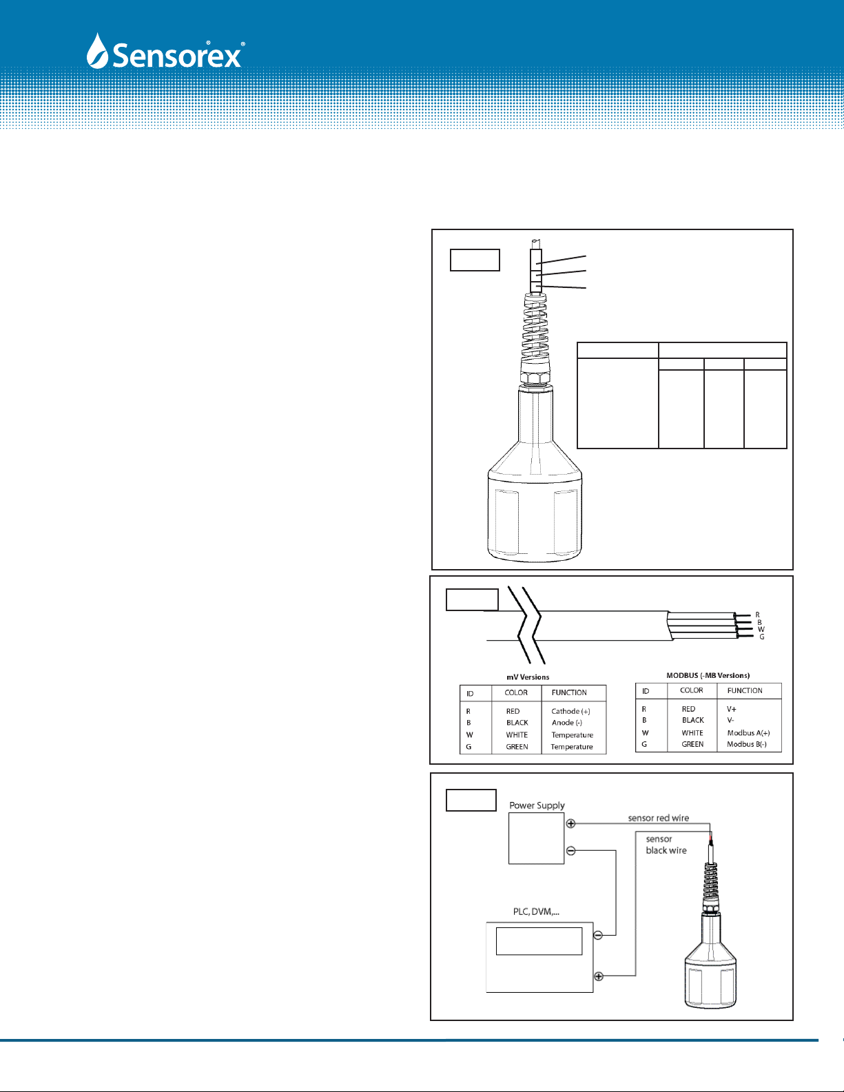
FIG.1 for sensor ID.
Introduction
PRODUCT INSTRUCTION SHEET
Parts covered by this product data sheet include:
DO6400, DO6400TC, DO6441, DO6442, DO6441TC, DO6442 TC
Electrical Connections
Dissolved Oxygen Sensor Care and Use Instructions
Product Instructions
Getting Your DO Sensor Ready to Use
DO6400 and DO6400TC models(mV output):
Red wire of Sensor to DO input + (cathode)
Black wire of Sensor to DO input - (anode)
White and Green wires of Sensor to Temperature input
(see wiring FIG 2.)
DO6441, DO6441TC, DO6442, DO6442TC (4-20mA output):
Red wire of Sensor to DO input + (cathode)
Black wire of Sensor to DO input - (anode)
(see wiring FIG 3.)White and Green wires of Sensor to Temperature input
Your DO sensor is shipped to you dry and is not ready for use. See
steps #1, #7, #8, #9 and #10 of the “Sensor Reconditioning”
section of this sheet for instructions on sensor preparation.
The installed membrane shipped with the probe is usable if it
passes the leak test in step #8. Maintenance items included
with your sensor include: 1 each membrane lock tool, 2 each
PTFE or HDPE membranes, 2 each membrane o-rings and
250mL of electrolyte.
FIG. 1
FIG. 3
Form: InstrDO6400-B [Rev: 2016-02-19]
Part Number Shrink Colors
#1 #2 #3
DO6400 N/A N/A N/A
DO7400 white N/A N/A
DO6441 yellow N/A N/A
DO6442 green yellow N/A
DO7441 yellow white N/A
DO7442 green yellow white
#3
#2
#1
Cable Shrink
4-20mA mV output models
DO6441, DO6441TC, DO6442, DO6442TC (Modbus485 output):
Red wire of Sensor to DO input + (cathode)
Black wire of Sensor to DO input - (anode)
(see wiring FIG 3.)White and Green wires of Sensor to Temperature input
FIG. 2
Page 2 of 8
PRODUCT INSTRUCTION SHEET
membrane lock
spacer
membrane
FIG. 4
FIG. 5
FIG. 6 FIG. 7
o-ring
Form: InstrDO6400-B [Rev: 2016-02-19]
large
o-ring to
seal body.
Seats in
groove in
bottom
cap.
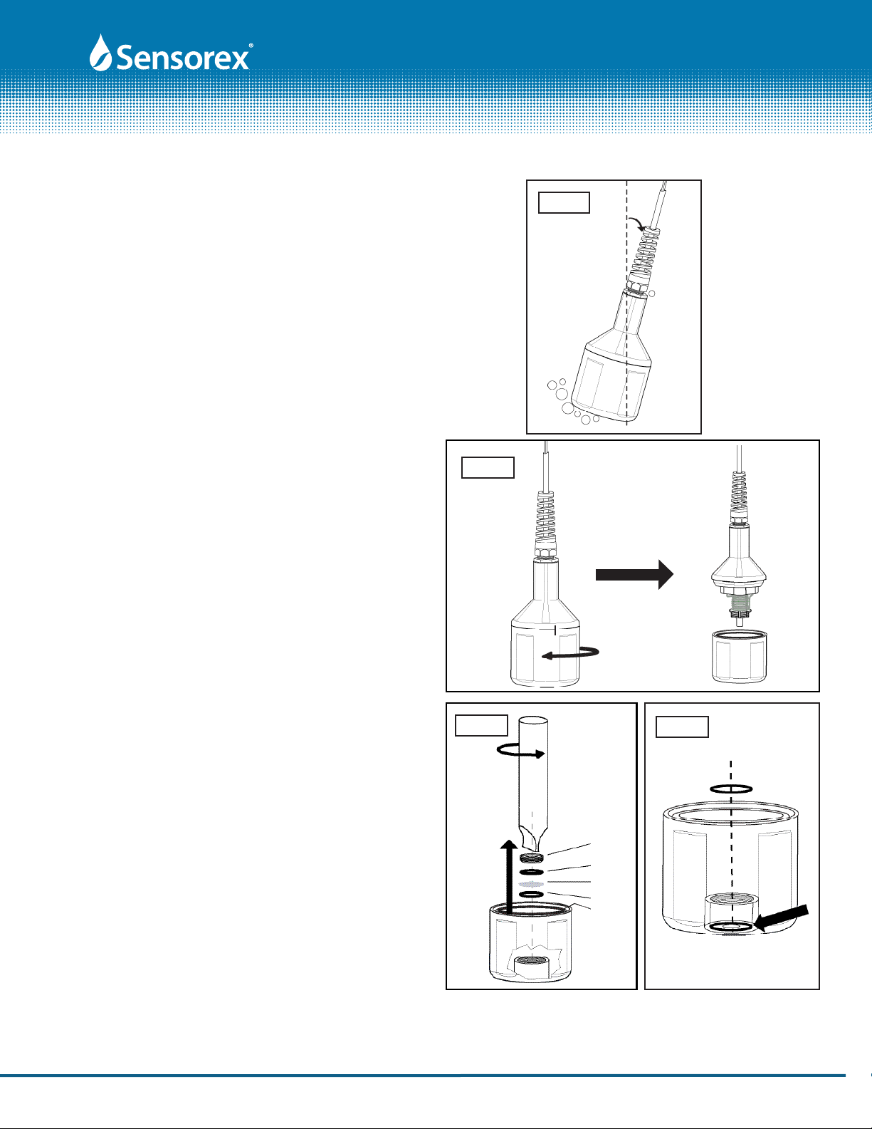
Mounting Your DO Sensor
Submersion mounting of the sensor is recommended. To
prevent air bubbles from becoming trapped on the membrane
and producing falsely high DO readings, it is recommended
that the sensor be mounted at a slight angle (SEE FIG. 4).
Sensor Re-Conditioning
1. Unscrew the lower body from the upper body (FIG. 5).
2. Safely dispose of the electrolyte (Sodium Chloride solution
(salt water). Make sure o-ring does not fall out of cap.
3. Using the Membrane Tool, unscrew the Membrane Lock in
the lower body as shown in FIG. 6
4. Remove and dispose of the membrane and its o-ring as
show in FIG 7.
See page 3 for more sensor reconditioning.

Page 3 of 8
PRODUCT INSTRUCTION SHEET
membrane
lock
spacer
membrane
o-ring
FIG. 8 FIG. 9
FIG. 10
Form: InstrDO6400-B [Rev: 2016-02-19]
ALIGN TOP AND BOTTOM
CAP TO MARKS.
DO NOT OVER
TIGHTEN!
FIG. 11
Small gap
when aligned
correctly
Sensor Re-Conditioning(cont.)
5.To clean, take the top part of the sensor and immerse in
distilled white vinegar (3% acetic acid) for about 30 minutes.
If you don't have vinegar, you can use a SOFT toothbrush,
dish washing powder, and clean water, clean the cathode,
anode, and plastic between them. Rinse all components
thoroughly with clean water after cleaning (SEE FIG. 8).
6. First, install a new o-ring into the lower body membrane
cavity (the o-ring must go all the way to the bottom as
shown in FIG 7), then a new membrane (remove paper back-
ing from membrane before installing), then the spacer. Using
the Membrane tool, install the Membrane Lock on top of
the spacer as shown in FIG. 9. Make sure cap is upright (not
sideways) when screwing in lock.
7. Inspect the membrane for wrinkles--replace if it is wrinkled.
8. Pour some clean water into the lower body and look for
leakage around the membrane (SEE FIG. 10)--replace it if
there is leakage. If there is no leakage, dispose of the water.
9. Fill the bottom cap to the top with fresh electrolyte.
10. Keep the sensor upright so that the cable is pointed
upwards(not sideways). Screw the bottom cap onto the
upper body until the alignment marks on the top of the
sensor and the bottom cap are aligned. There will be a very
small gap at the joint between the sensor's cap and upper
body. See FIG. 11.
NOTES: Sensor bottom cap must be used only on the sensor it is received on.
Do not mix bottom caps. This could cause leaking or measuring errors.
Do not overtighten the bottom cap past the alignment marks as shown in
FIG. 11
Replace large o-ring when reconditioning the sensor. The o-ring should
be lubricated before installation. See large o-ring position in FIG. 6. The
o-ring is pre-lubricated. Be sure not to get o-ring lubricant on the sensor's
membrane.

Allow the sensor to stabilize. A few minutes is adequate for a
new probe or new membrane. If recalibrating a probe with an
old membrane, several minutes may be required for stabiliza-
tion.
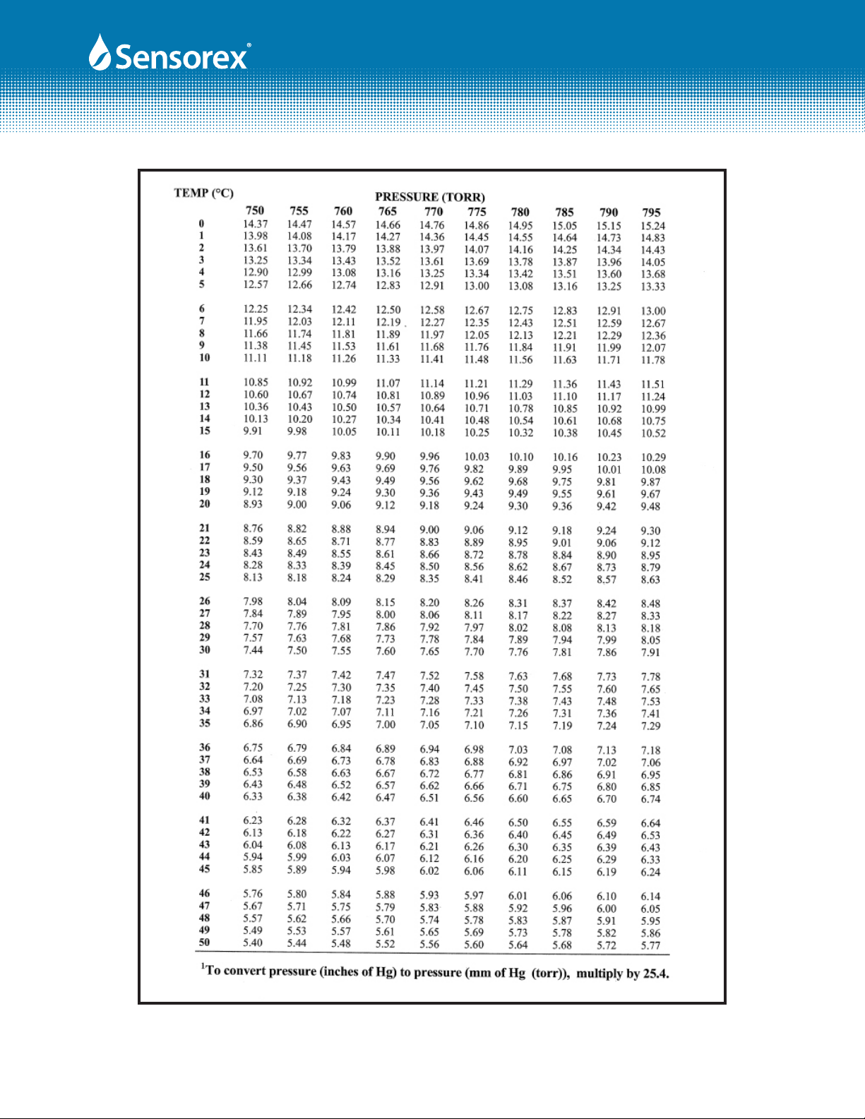
Determine the atmospheric temperature and the barometric
pressure and salinity. Using the charts on pages 5-7 of this
instruction manual, determine the saturation value for this
temperature, pressure and salinity. This 100% saturation value
is equal to the millivolt output reading of the sensor (for series
DO6400 and DO7400), or equal to the milliamp output of the
sensor (for series DO6441, DO6442, DO7441, DO7442).
When the output is stable, indicating that temperature equal-
izing has taken place, measure the level of saturation. For
example, using the DO6400/T electrode, a reading of 36.0 mV
could be a typical saturated output reading. For the DO6442/T
probe, a saturated reading in air could provide a calibration
reading of 12.0 mA.
Most customers will find that this single point reading is
satisfactory. The assumption is that the millivolt probes series
DO6400 and DO7400 will read 0.0 mV when there is 0.00
ppm O2. For series DO6441, DO6442, DO7441, DO7442, the
assumption is the milliamp output of the sensor will be 4.25
mA. The output of all of these sensors are linear. For custom-
ers routinely measuring 3 or more ppm, the assumptions will
provide excellent results. Using these 2 points, a line may be
drawn between these 2 points. All subsequent readings will
fall on this line, or for higher values, beyond the extended line
to higher levels of O2 saturation at higher pressures.
Calibration
First, ensure that the sensor is properly connected to the
instrumentation circuitry. A visual display must be available to
read the sensor output. For sensors that have been installed
in service, gently wipe the membrane using a soft cloth to
remove accumulated biological debris. The Probe may be
calibrated in air, or in air-saturated water. Please calibrate out
of direct sunlight, which may effect accurate calibration. The
simplest method is to calibrate in air. Simply hold sensor in air
and take reading (wait for reading to equilibrate). If calibrat-
ing in air saturated water, ensure that the water is saturated,
by agitating the water sample. Place the probe just below the
surface of the water level.
PRODUCT INSTRUCTION SHEET
Should you expect readings below 2 ppm, you should
perform a 2 point calibration. Prepare a solution of satu-
rated sodium sulfite (Na2SO3) in water. 17g Sodium sulfite
in 125mL DI water is more than enough. Sodium sulfite may
not reach a true zero output on your display but it should
read less than 2 mV for series DO6400 and DO7400, and
less than 5mA for series DO6441, DO6442, DO7441, DO7442
after 5 minutes.
Calibration should be performed periodically to ensure the
best accuracy. The application will determine the interval of
calibration. The user is responsible to understand how often
calibration will be performed for that application.
Page 4 of 8 Form: InstrDO6400-B [Rev: 2016-02-19]
Calculating DO in % Saturatio or ppm/
mg/L
Calculating Dissolved oxygen (DO):
% DO for mV sensors only (note that % DO us independent
of temperature):
1) Take Air reading in mV or mA and record value
2) Measure unknown sample of water mV or mA
3) Unknown/Air x 100% = % DO
a. Example: mV Sensor in air = 40mV, unknown sample
water = 20mV
20/40 x 100% = 50% Saturation
% DO for mA sensors only (note that % DO us independent of
temperature):
ppm or mg/L (temperature, salinity and pressure
dependent)
1) Take Air reading in mV or mA and record value
2) Take readings for: temperature, salinity, pressure
(pressure only if calibration and measurement are at different
elevations) and record values
3) If fresh water then salinity = 0, use chart on page 6,
column “0”, otherwise find salinity column and use that value
a. Example 1: Air = 20mA, Unknown water = 12mA,
temperature = 25°C, salinity = 0
i. 0.5 x 8.24ppm = 12mA (12mA is 50% of 4-20mA scale
(you cannot use 12/20mA) = 4.12ppm)
b. Example 2: Air = 40mV, Unknown water = 20mV,
temperature = 25°C, salinity = 0
i. 20/40 x 8.24ppm = 4.12ppm
c. Example 2: Air = 40mV, Unknown water = 20mV,
temperature = 25°C, salinity = 30ppt
i. 20/40 x 6.95ppm = 3.48ppm

Page 5 of 8
PRODUCT INSTRUCTION SHEET
Outline and Dimensions
DO6400 and DO6441, 6442
DO6400TC
Sensor Storage
If long-term storage of probes is required, empty electrolyte
out of probe, rinse with clean water and remove and discard
the membrane and the membrane o-ring. Store dry and empty.
Sensor Repair
Do not attempt to repair any part of the sensor. If the sensor's
cable is damaged, consult the factory for details.
SPECIFICATIONS
Sensor Materials
Top and Bottom Cap: PPO
Sensor Body: POM
Anode: Zinc wire
Cathode: Silver
Output at 100% Saturation (mV models)
PTFE Membrane: 36+/-8 mV
HDPE Membrane: 48+/-8 mV
Output at 100% Saturaion (mA models)
DO6441: 18-22mA
DO6442: 11-14mA
Output at 0% Saturation (mV models)
PTFE & HDPE Membrane: <1mV
Output at 0% Saturation (mA models) <4.6mA
Temperature Range
Max: 50 deg C
Min: 0 deg C
Response Time
PTFE Membrane: 5 minutes from 100% to 0%
Oxygen (<1mV or 4.5mA)
Water Flow Rate: Min 2 inch/second across membrane.
Wetted Materials
Body: PPO
Membrane: PTFE or HDPE
Cable: 4-conductor, 24AWG, Copper/PVC,
polyurethane outer jacket.
Wiring
DO6400, DO6441*, DO6442* Red = + , Black = -
DO6400/TC Red = + , Black = -, White & Green = Temp,
Green = Temp
Power Requirement: DO6441, DO6441TC, DO6442, DO6442TC
24 V DC, min 150mA
Note: * 4-20mA output versions
Form: InstrDO6400-B [Rev: 2016-02-19]

TEMPERATURE SALINITY- in parts per thousand (ppt)
deg C deg F 0 5 10 15 20 25 30 35 40
0 32 14.6 14.11 13.64 13.18 12.74 12.31 11.9 11.5 11.11
1 33.8 14.2 13.73 13.27 12.83 12.4 11.98 11.58 11.2 10.83
2 35.6 13.81 13.36 12.91 12.49 12.07 11.67 11.29 10.91 10.55
3 37.4 13.45 13 12.58 12.16 11.76 11.38 11 10.64 10.29
4 39.2 13.09 12.67 12.25 11.85 11.47 11.09 10.73 10.38 10.04
5 41 12.76 12.34 11.94 11.56 11.18 10.82 10.47 10.13 9.8
6 42.8 12.44 12.04 11.65 11.27 10.91 10.56 10.22 9.89 9.57
7 44.6 12.13 11.74 11.37 11 10.65 10.31 9.98 9.66 9.35
8 46.4 11.83 11.46 11.09 10.74 10.4 10.07 9.75 9.44 9.14
9 48.2 11.55 11.19 10.83 10.49 10.16 9.84 9.53 9.23 8.94
10 50 11.28 10.92 10.58 10.25 9.93 9.62 9.32 9.03 8.75
11 51.8 11.02 10.67 10.34 10.02 9.71 9.41 9.12 8.83 8.56
12 53.6 10.77 10.43 10.11 9.8 9.5 9.21 8.92 8.55 8.3
13 55.4 10.53 10.2 9.89 9.59 9.3 9.01 8.74 8.47 8.21
14 57.2 10.29 9.98 9.68 9.38 9.1 8.82 8.55 8.3 8.04
15 59 10.07 9.77 9.47 9.19 8.91 8.64 8.38 8.13 7.88
16 60.8 9.86 9.56 9.28 9 8.73 8.47 8.21 7.97 7.73
17 62.6 9.65 9.36 9.09 8.82 8.55 8.3 8.05 7.81 7.58
18 64.4 9.45 9.17 8.9 8.64 8.39 8.14 7.9 7.66 7.44
19 66.2 9.26 8.99 8.73 8.47 8.22 7.98 7.75 7.52 7.3
20 68 9.08 8.81 8.56 8.31 8.07 7.83 7.6 7.38 7.17
21 69.8 8.9 8.64 8.39 8.15 7.91 7.69 7.46 7.25 7.04
22 71.6 8.73 8.48 8.23 8 7.77 7.54 7.33 7.12 6.91
23 73.4 8.56 8.32 8.08 7.85 7.63 7.41 7.2 6.99 6.79
24 75.2 8.4 8.16 7.93 7.71 7.49 7.28 7.07 6.87 6.68
25 77 8.24 8.01 7.79 7.57 7.36 7.15 6.95 6.75 6.56
26 78.8 8.09 7.87 7.65 7.44 7.23 7.03 6.83 6.64 6.46
27 80.6 7.95 7.73 7.51 7.31 7.1 6.91 6.72 6.53 6.35
28 82.4 7.81 7.59 7.38 7.18 6.98 6.79 6.61 6.42 6.25
29 84.2 7.67 7.46 7.26 7.06 6.87 6.68 6.5 6.32 6.15
30 86 7.54 7.33 7.14 6.94 6.75 6.57 6.39 6.22 6.05
31 87.8 7.41 7.21 7.02 6.83 6.65 6.47 6.29 6.12 5.96
32 89.6 7.29 7.09 6.9 6.72 6.54 6.36 6.19 6.03 5.87
33 91.4 7.17 6.98 6.79 6.61 6.44 6.26 6.1 5.94 5.78
34 93.2 7.05 6.86 6.68 6.51 6.33 6.17 6.01 5.85 5.69
35 95 6.93 6.75 6.58 6.4 6.24 6.07 5.92 5.76 5.61
36 96.8 6.82 6.65 6.47 6.31 6.14 5.98 5.83 5.68 5.53
37 98.6 6.72 6.54 6.37 6.21 6.05 5.89 5.74 5.59 5.45
38 100.4 6.61 6.44 6.28 6.12 5.96 5.81 5.66 5.51 5.37
39 102.2 6.51 6.34 6.18 6.03 5.87 5.72 5.58 5.44 5.3
40 104 6.41 6.25 6.09 5.94 5.79 5.64 5.5 5.36 5.22
PRODUCT INSTRUCTION SHEET
Page 6 of 8 Form: InstrDO6400-B [Rev: 2016-02-19]
PRODUCT INSTRUCTION SHEET
Page 7 of 8 Form: InstrDO6400-B [Rev: 2016-02-19]

PRODUCT INSTRUCTION SHEET
Page 8 of 8 Form: InstrDO6400-B [Rev: 2016-02-19]
This manual suits for next models
8
Table of contents
Other Sensorex Accessories manuals


Popular Accessories manuals by other brands

turck
turck BC3-M12-AP6X 15M quick start guide

Sealey
Sealey LED110S instructions

Klimasan
Klimasan S 56 SC operating manual

PCB Piezotronics
PCB Piezotronics 208A33 Installation and operating manual

PRIMAVERA
PRIMAVERA Simply Silent Important information

Outdoor Revolution
Outdoor Revolution Compactalite Pro Integra 325 instructions


Silvercrest
Silvercrest B69PF manual

Graphtech
Graphtech Ghost user guide

Chef's Choice
Chef's Choice Pronto Diamond Hone 463 manual

S+S Regeltechnik
S+S Regeltechnik Premasreg 7165 Operating Instructions, Mounting & Installation

Carefree
Carefree FREESTYLE EVOLUTION installation manual

SkyBound
SkyBound TRAMPOLINE MAT installation manual