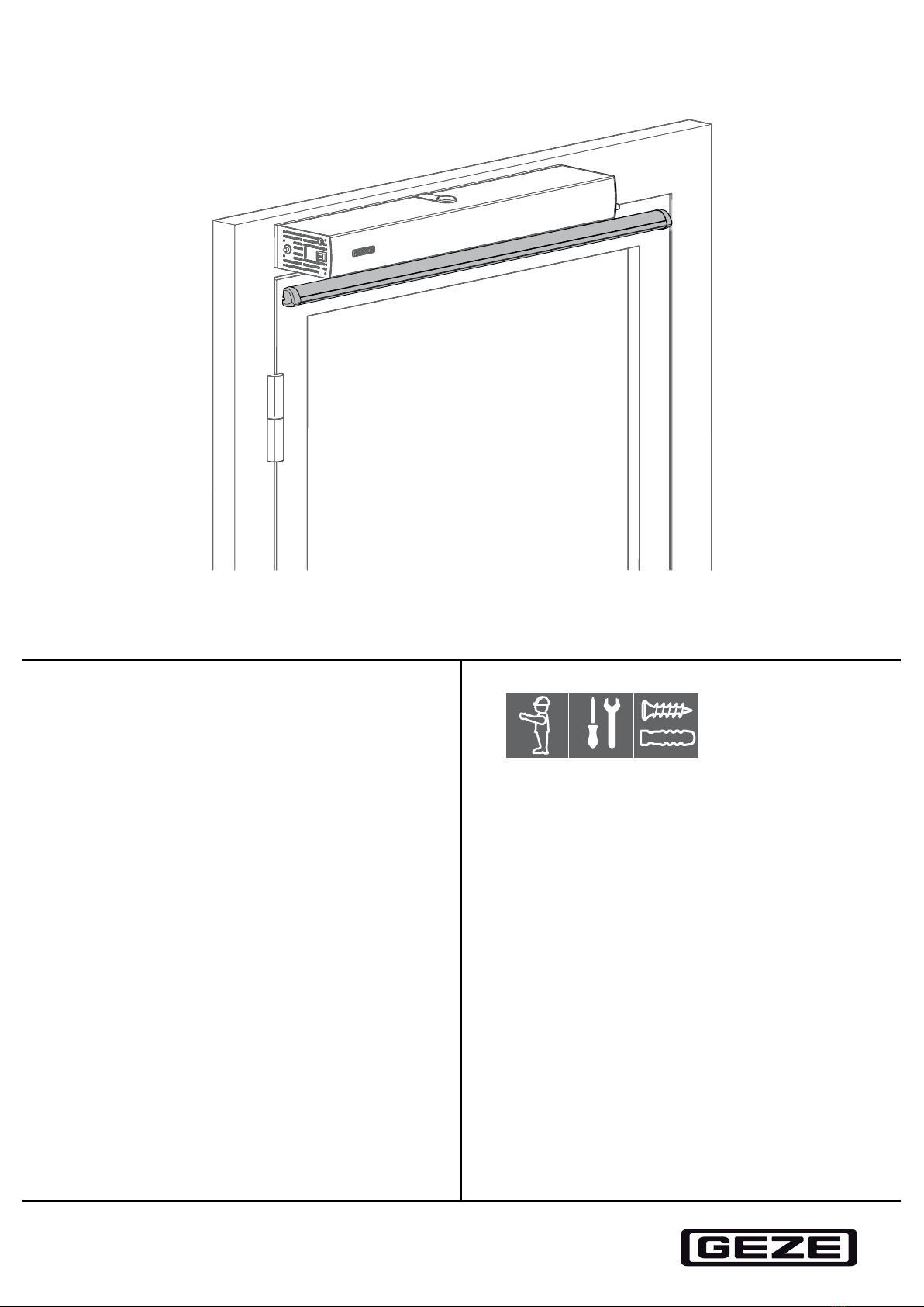
GC 338 Presence sensor
2
Contents
Symbols and illustrations .................................................................................................................................................3
Abbreviations........................................................................................................................................................................3
Product liability.....................................................................................................................................................................3
1 Safety ..........................................................................................................................................................................3
1.1 Intended use.......................................................................................................................................................................................................3
1.2 Safety notices ....................................................................................................................................................................................................3
1.3 Safety conscious working .............................................................................................................................................................................4
1.4 Environmentally conscious working .........................................................................................................................................................4
2 Validity.........................................................................................................................................................................4
3 Description ................................................................................................................................................................4
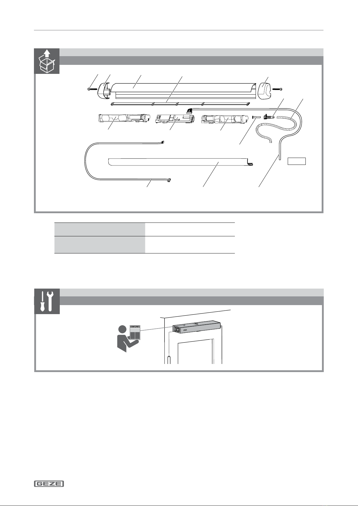
3.1 Supplied by GEZE..............................................................................................................................................................................................5
4 Work to be done before installation.................................................................................................................5
4.1 Installing the drive............................................................................................................................................................................................5
4.2 Preparing the door transmission cable.....................................................................................................................................................6
5 Installation .................................................................................................................................................................7
5.1 Preparation..........................................................................................................................................................................................................7
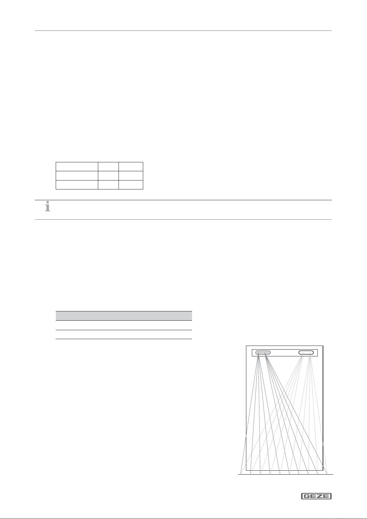
5.2 Position of the modules..................................................................................................................................................................................8
5.3 Installation of the modules ...........................................................................................................................................................................9
5.4 Preparing the transmitter and the receiver for the other side of the door............................................................................... 13
5.5 Special installation situations.................................................................................................................................................................... 13
6 Commissioning ..................................................................................................................................................... 14
6.1 Drive teach-in.................................................................................................................................................................................................. 14
6.2 Sensor teach-in............................................................................................................................................................................................... 14
6.3 Putting the drive and sensor into operation........................................................................................................................................ 17
7 Last assembly steps after commissioning................................................................................................... 18
8 Special installation situations .......................................................................................................................... 19
8.1 Installation on 2-leaf doors......................................................................................................................................................................... 19
8.2 Door leaves which move towards one another.................................................................................................................................. 19
8.3 Strong eects of external light ................................................................................................................................................................. 19
8.4 Installation on doors with door sot..................................................................................................................................................... 19
8.5 Installation on re protection doors / glass doors............................................................................................................................. 20
8.6 Installation on doors with horizontal pull handles or panic bars................................................................................................. 20
8.7 Installation on doors with vertical pull handles. ................................................................................................................................ 21
8.8 Installation on revolving doors................................................................................................................................................................. 21
9 LED status and troubleshooting ..................................................................................................................... 22
9.1 LED status display.......................................................................................................................................................................................... 22
9.2 Troubleshooting............................................................................................................................................................................................. 23
10 Technical data........................................................................................................................................................ 26
11 Accessories / Spare parts................................................................................................................................... 27
Original operating instructions for device version V.03