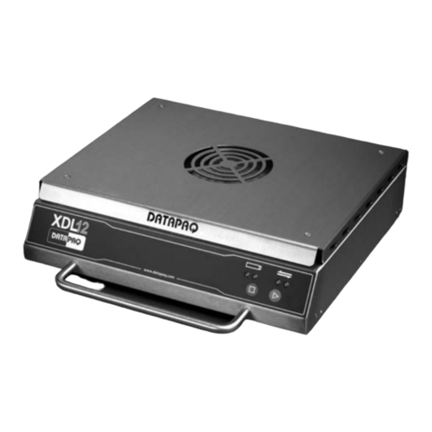
Sensornet ORYX DTS User manual

This page intentionally blank.


Oryx DTS User Manual v4 Page i
CONTENTS
SAFETY..................................................................................................................1
G
ENERAL
S
AFETY
.................................................................................................1
L
ASER
S
AFETY
......................................................................................................2
INTRODUCTION - SYSTEM OVERVIEW.......................................................4
OPTICAL AND ELECTRICAL CONNECTIONS............................................7
C
OMMUNICATIONS
O
PTIONS
...............................................................................11
FRONT PANEL INDICATORS.........................................................................13
INSTALLATION GUIDELINES .......................................................................15
P
HYSICAL INSTALLATION
....................................................................................15
S
OFTWARE INSTALLATION
...................................................................................15
GETTING STARTED .........................................................................................17
THE ORYX DATA COLLECTOR (ODC)........................................................20
SELECTING ROOT
&
ADDING AN ORYX
.................................................................20
C
ONFIGURING THE
O
RYX
....................................................................................29
T
HE
D
ATA
&
L
OG FILES
......................................................................................41
GUIDE TO DTS MEASUREMENTS AND THE ORYX CONFIGURATION
WIZARD...............................................................................................................46
B
ACKGROUND TO
DTS........................................................................................46
GRAPHICAL USER
I
NTERFACE
..............................................................................49
O
RYX CONFIGURATION WIZARD
..........................................................................52
DOUBLE-ENDED MEASUREMENTS.............................................................68
INTRODUCTION TO DOUBLE
-
ENDED
.....................................................................68
C
ONFIGURING A DOUBLE
-
ENDED MEASUREMENT
................................................69
THE ORYX DATA VIEWER.............................................................................74
SOFTWARE INSTALLATION
&
LICENSING
..............................................................74
S
ETTING ROOT
&
SELECTING AN ORYX
................................................................75
VIEWING LIVE DATA
............................................................................................78
VIEWING HISTORICAL DATA
.................................................................................83
CARE & MAINTENANCE.................................................................................86

TROUBLESHOOTING.......................................................................................87
SPECIFICATIONS..............................................................................................89
P
ERFORMANCE SPECIFICATIONS
..........................................................................89
OPERATING
&
PHYSICAL SPECIFICATIONS
............................................................90
DIMENSIONS
........................................................................................................93
W
ARRANTY
.........................................................................................................93


This page intentionally blank.

Oryx DTS User Manual v4 Page 1
SAFETY
GENERAL SAFETY
The following section provides Warnings, Cautions and Notes covering general
safety aspects for the Oryx DTS. Please read all of the safety and operational
warnings before connecting and operating this product.
WARNING! THIS IS A W
ARNING SYMBOL. THIS
SYMBOL IS
USED THROUGHOUT THE USER GUIDE WHENEVER THERE IS
A RISK OF PERSONAL INJURY. ENSURE THAT THESE
WARNINGS ARE READ AND UNDERSTOOD AT ALL TIMES.
CAUTION! This is a Caution symbol. This symbol is used
throughout the user guide whenever there is a risk of
damaging the Oryx DTS system. Ensure that these warnings
are read and understood at all times.
NOTES:
Used throughout the user guide to provide additional information, hints and tips.
WARNING! THE ORYX DT
S IS HEAVY. ENSURE A
DEQUATE
CARE IS TAKEN WHEN LIFTING AND MOVING. THE UNIT
SHOULD BE MOUNTED ON A SUITABLE SURFACE OR RACK
MOUNT CAPABLE OF SUPPORTING THE WEIGHT. THE ORYX
DTS WEIGHS 7KG.
CAUTION! Ensure the ORYX DTS is connected to a suitable
electrical supply. 12 – 24VDC should be used.
WARNING! ENSURE THE
ORYX DTS IS ADEQUATE
LY
EARTHED. FAILURE TO OBSERVE THIS WARNING MAY
PRESENT A RISK OF ELECTRIC SHOCK.

Page 2 Oryx DTS User Manual v4
WARNING! THERE ARE N
O USER SERVICEABLE P
ARTS
INSIDE. UNDER NO CIRCUMSTANCES SHOULD THE OUTER
CASING OF THE ORYX DTS BE REMOVED. FAILURE TO
OBSERVE THIS WARNING MAY PRESENT A RISK OF
ELECTRIC SHOCK.
WARNING! DO NOT OPER
ATE THE ORYX DTS IN
AN
EXPLOSIVE OR FLAMMABLE ATMOSPHERE. FAILURE TO
OBSERVE THIS WARNING MAY PRESENT A RISK OF
EXPLOSION.
CAUTION! The ORYX DTS should only be operated by suitably
qualified personnel.
CAUTION! Never operate the ORYX DTS if any damage is
observed. Contact Sensornet Ltd for advice.
LASER SAFETY
The ORYX DTS is a Class 1M laser product.
The ORYX distributed sensing system incorporates a pulsed laser device whose
invisible output radiation is potentially hazardous if viewed directly by eye. The laser
radiation emission from the laser within the ORYX DTS is permanently coupled into
a 50/125 multimode optical fibre whose end is terminated with an APC, angled
polished optical fibre connector.
The Oryx DTS should be interfaced to a test fibre, using patch cord or pigtail
assembly, fitted with an APC connector. The far end of the test fibre should be
terminated to prevent free-space emission of laser radiation from the fibre end. It is
recommended that where possible, fusion splices or APC connectors be utilized
throughout the optical sensing network.
Because of the potential hazard posed by laser radiation being emitted from an
exposed fibre end, the following safety warnings, cautions and notices should be
observed.

Oryx DTS User Manual v4 Page 3
WARNING! DO NOT LOOK
AT OR EXAMINE EXPOSE
D FIBR
E
OR CONNECTOR ENDS WHENEVER THE DTS IS IN
OPERATION.
WARNING! AVOID EYE E
XPOSURE TO THE INVIS
IBLE LASER
RADIATION EMITTED FROM FIBRE CONNECTORS OR
EXPOSED FIBRE ENDS.
WARNING! DO NOT EXAM
INE OR INSPECT EXPOS
ED FIBRE
OR CONNECTOR ENDS USING A VIEWING AID SUCH AS AN
EYE LOUPE OR MICROSCOPE WHILE POWER IS APPLIED TO
THE DTS.
WARNING! DO NOT UNDE
RTAKE FUSION SPLICIN
G OR
SIMILAR FIBRE JOINTING WHEN THE DTS IS IN OPERATION.
WARNING! THE DTS SYS
TEM CONTAINS NO USER
SERVICEABLE PARTS AND THE PROTECTIVE HOUSING
FULLY ENCLOSES A CLASS 3B (EMBEDDED) LASER DEVICE.
UNDER NO CIRCUMSTANCES SHOULD THE PROTECTIVE
HOUSING BE REMOVED.

Page 4 Oryx DTS User Manual v4
INTRODUCTION - SYSTEM OVERVIEW
Figure 1 - The Oryx DTS
The Sensornet ORYX DTS unit is an intelligent remote logging unit for collecting
fully distributed temperature data over installed fibre optic cable. The device will
autonomously record the signals from up to 4 fibres, store this data on-board in
non-volatile memory and transmit the data back to a base station computer (or
download to a local PC / laptop). 32MB of on-board memory is available which is
sufficient to store approximately 600 separate DTS measurements. The raw data is
processed (and temperature calculations are performed) on the base station or
laptop and this is where the data is permanently stored. The base station server
runs Sensornet software which communicates with multiple Oryx units in the field
and allows configuration changes from a central control room (CCR). Users can
connect to the base station to view the temperature data using Sensornet software

Oryx DTS User Manual v4 Page 5
or other third party tools. The data files can also be imported into a spreadsheet
application.
Figure 2 - Overview of communications & connectivity
The Oryx is provided with dedicated software to communicate with and configure
the remote DTS unit(s) – Oryx data collection (ODC) software. It is important to note
that since the temperature calculation is performed on the base station server, third
party communication to the Oryx its self is not required and only occurs through the
Sensornet ODC software. Because of the sophisticated nature of the Oryx and the
volume of data collected and transmitted back to the base station, a proprietary
protocol has been established for direct communication with the Oryx. This currently
operates over a serial RS232 communications link. Sensornet provides several
options for this communications link, such as radio or GPRS modems, serial-over-
Ethernet or alternatively, existing communications infrastructure can be used if the
link is transparent to the protocol used. If a communications link is not available, the
ORYX unit will buffer measurement data on board until a link is established or drive-
by data collection is undertaken.
Other features of the Oryx are:
•On-board real-time clock (battery backed)
•Two independent PT100 resistance probes for aiding calibration
•Robust, fault tolerant communications (data is stored on-board until
download acknowledged)
•Power saving feature – idle mode activated if no measurements scheduled
for >1min
•Low power operation – Solar or Wind power can be used

Page 6 Oryx DTS User Manual v4
•Self-protecting features – idle mode activated if environmental temperature
out of range or power supply voltage outside limits

Oryx DTS User Manual v4 Page 7
OPTICAL AND ELECTRICAL CONNECTIONS
The following diagram illustrates the connections to the Oryx DTS unit. All electrical
connections are by removable screw terminals and optical connectors are E2000
APC type.
Figure 3 - Oryx Connector Panel
LIST OF CONNECTIONS:
1. Input power
2. Serial RS232 communications ports, Com1 & Com2
3. PT100 external probe connections
4. Fibre Optic connector panel
5. Earthing point
6. Laser emission warning symbol
1 2
3
4
5 6

Page 8 Oryx DTS User Manual v4
The table below lists all of the electrical connections.
TABLE OF CONNECTIONS
Label
Connection
Note
0V Negative terminal of
supply
+V Positive terminal of supply
GND Ground
Rx Com Receive Connect to Tx terminal on
PC / modem com port
Tx Com Transmit Connect to Rx terminal on
PC / modem com port
I1+ Current source
These terminals are for a
standard 4 wire
connection to a platinum
resistance thermometer
V1+ Sensing terminal
V1- Sensing terminal
I1- Current sink
Each of the electrical connector terminal blocks can be removed for ease of wiring.
It is recommended that the Oryx unit be earthed, especially in out-door installations.
Optical connections are made by simply inserting the E2000 connector into the
appropriate optical channel. Press the latch & pull to disconnect (see Figure 4).

Oryx DTS User Manual v4 Page 9
Figure 4 - Connecting and disconnecting the E2000 optical connector
NOTE: Ensure the optical connector is pushed firmly into the housing and latches to
obtain proper mating
Typical connector loss is 0.1 – 0.3dB. Values above 0.4dB would warrant cleaning
the connectors. The fibre optic connector panel can be removed by unscrewing the
four knurled thumb screws and carefully removing the panel. There is sufficient
slack on the inside fibre pigtails to allow removal and cleaning.
CAUTION! If one of the internal optical connectors is damaged,
the unit will need repair at Sensornet. Only remove the Optical
Connector Panel if a dirty connector has been inserted or the
optical connector loss cannot be reduced by cleaning the
external connector.
In cases where the DTS is connected and disconnected frequently (e.g. if the Oryx
is transported to different sites for measurements), the use of an external ‘sacrificial’

Page 10 Oryx DTS User Manual v4
patch lead is recommended. This will add a small amount of additional loss but if
the patch-lead is damaged, it can easily be replaced.
NOTE: Please ensure the optical connectors are clean before inserting into the
Oryx. Dirty optical connectors are a major source of signal loss. Clean the optical
connector with a suitable cleaning cassette or alcohol-damped swab. It may be
necessary to remove the Fibre Optic Connector Panel and clean the connector
inside the Oryx if a dirty connector has been inserted
Specialist connector inspection microscopes are useful for verifying that connectors
are clean and free of foreign material. Video inspection scopes can also be used to
view the condition of connectors. There are two methods for cleaning connectors
and couplings which are approved by Sensornet Ltd. The technique used is
dependent on the type of contamination. If the connector has been exposed to
slight dust contamination, the preferred method is using a ‘cassette style’ cleaning
tape. If the connector has been exposed to grease, lint free tissues wetted with
alcohol or pre-soaked wet wipes should be used.
WARNING! UNDER NO CI
RCUMSTANCES SHOULD
CONNECTIONS BE INSPECTED WHILE THE DTS SYSTEM IS
LIVE AND OPERATING.

Oryx DTS User Manual v4 Page 11
COMMUNICATIONS OPTIONS
. Communication options
By default, the Oryx DTS ships with both com ports configured for direct serial
(RS232) connection. This mode is used in the following situations:
•Direct connection of PC or laptop to serial port
•Connection of Oryx to an Ethernet-to-serial device server
•Connection to a Radio or GPRS data modem
These communications links typically provide “always up” connection and are
transparent to the protocol used.
Figure 5 - Communication options

Page 12 Oryx DTS User Manual v4
The Oryx DTS also supports modem commands (AT command set) for analogue
communications links and this mode is used in the following situations:
•A telephone line is used with an analogue modem
•GSM modem using the GSM network
The Oryx should have one of the com ports configured for modem operation by
setting the baud rate, initialization string and dial out telephone number. At the
base-station, a corresponding modem should be installed and configured using the
ODC software, with the matching baud rate and the Oryx telephone number.
If a radio or GPRS modem-router is installed, these should be configured as per the
manufacturer instructions at the remote Oryx site and, if applicable, the base-
station.
NOTE: For GPRS, the user will be required to provide a SIM card with fixed IP
address suitable for machine-machine communications. Your network provider
should be able to help with the configuration & VPN (virtual private network)
settings.
If using a serial-Ethernet converter, only one device needs to be installed at the
Oryx site but software device drivers will need to be installed on the PC / laptop to
map a TCP socket to a virtual com port.

Oryx DTS User Manual v4 Page 13
FRONT PANEL INDICATORS
Figure 6 - Oryx Front Panel – description of labels below.
INPUT POWER
When illuminated, this indicates that power is applied and the DTS is in operation.
OPTICS POWER
When illuminated, this indicates that power is applied to the optics & laser unit.
During an idle period, this LED is not illuminated and no power is applied to the
optics and laser.
DATA ACQUISITION
When illuminated, this indicates that power is applied to the data acquisition board.
During an idle period, this LED is not illuminated and no power is applied to the
board.

Page 14 Oryx DTS User Manual v4
CHANNEL INDICATORS
These lights indicate which fibre channel is active. When lit, the relevant fibre is
being measured. If no lights are illuminated, the system is in idle or warm-up mode.
TEMP. ERROR
When illuminated, indicates that the DTS is outside its environmental operating
temperature range. No measurements will occur whilst this condition is present.
Once the temperature is back within range, the error will clear and the next
scheduled measurement will take place.
LASER ERROR
When illuminated, indicates that the laser is outside its operating temperature range
or a low laser output power. No measurements will take place while this condition is
present. Once the temperature is back within range, the error will clear and the next
scheduled measurement will take place.
FAULT
When illuminated, indicates a general system fault not specifically identified by the
other panel indicators.
STATUS
This LED will flash during normal operation of the Oryx DTS. In general the flash
rate is as follows:
System idle: slow flash
Active measurement in progress: fast flash
If this LED does not flash on / off or is constantly illuminated, the system is in an
error condition. However, note that during data transfer or heavy communications
activity, this LED may not flash.
DATA TX / DATA RX
These LEDs flash on & off indicating communications activity.
Table of contents
