sensortec NITTAN ST-H2-AS User manual
sensortec
sensortec
STH2AS
analogue addressable
heat sensor
instruction manual
NITTAN EUROPE LTD. Hipley Street, Old Woking, Surrey, England, GU22 9LQ. UK
Tel: +44 (0) 1483 769555 • Fax: +44 (0) 1483 756686
• Ref No: NISM/ST-H2-AS/02 • Date: 03.02.20 • Issue: 02
• sensortec • ST-H2-AS • analogue addressable heat sensor instruction manual
Quality System Certificate No. 041
Assessed to BS EN ISO 9001

Technical Manual: ST-H2-AS (Changes are subject to DCRN)
sensortec
sensortec
Ref No: NISM/ST-H2-AS/02 Date: 03.02.20 Issue: 02
• sensortec • ST-H2-AS • analogue addressable heat sensor instruction manual
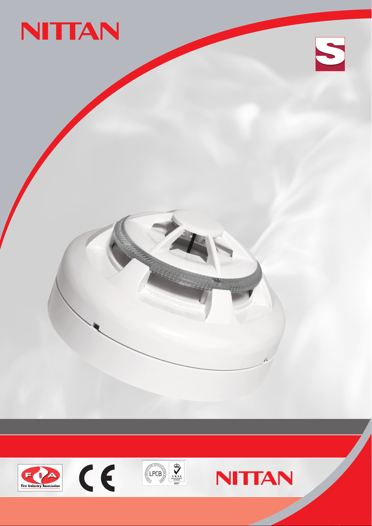
The ST-H2-AS is elegantly designed, low profile fire
sensor which is aesthetically pleasing, thus enabling it to
blend unobtrusively into modern working environments.
Section 1 - INTRODUCTION
The ST-H2-AS is an attractively-styled, low profile heat sensor for use
with Nittan ‘AS’ protocol control panels.
ST-H2-AS features:
• Low profile, stylish appearance
• EEPROM Addressing (Handheld Programmer)
• Low monitoring current
• Supplied with protective dust cover
• Patented OMNIVIEWTM 360°LED fire alarm indicator
• Remote indicator output
• Compatible with UB-4 and STB-4SE bases
• Polarised terminals
Section 2 - SENSOR MODELS
The ST-H2-AS photoelectric sensor has two terminals for connection
onto the two wire loop. The remaining terminal provides a switched
current sink function which operates when the sensor goes into
alarm condition, suitable for the operation of an auxiliary function
such as a remote indicator. Terminal 3 (RIL) is limited to 2mA.
Section 3 - BASE MODELS
A variety of bases are available for use with the ST-H2-AS sensor. It is
important to use the correct base for each application. The available
base models are:
i) UB-4 base: for standard use with ST-H2-AS series sensor.
ii) STB-4SE base: Similar to UB-4 base, except deeper.
CONTENTS:-
Section 1
Introduction Page 2
Section 2
Sensor Models Page 2
Section 3
Base Models Page 2
Section 4
Installation Page 3
Section 5
Maintenance &
Cleaning Page 3
Section 6
Technical
Specifications Page 6
Section 7
Environmental
Parameters Page 6
- Temperature Page 6
- Humidity Page 6
Section 8
EMC Page 6
Section 9
Address Setting Page 7
Section 10
Connections Page 8
Section 11
Dimensions Page 8
Section 12
Disposal Page 9
Section 13
ROHS Compliance
Statement Page 9
2

Technical Manual: ST-H2-AS (Changes are subject to DCRN)
sensortec
sensortec
Ref No: NISM/ST-H2-AS/02 Date: 03.02.20 Issue: 02
• sensortec • ST-H2-AS • analogue addressable heat sensor instruction manual
Section 4 - INSTALLATION
In normal use, the ST-H2-AS sensor will be installed at ceiling level.
Pass the field wiring through the cable hole in the centre and from
the rear of the base. Offer up and affix the base to the ceiling or
conduit fitting with screws via the base mounting holes. Connect
the field wiring to the base terminals, as detailed on page 8 making
sure the wiring does not obstruct fitting of the sensor head. Fit the
sensor head by inserting it into the base and turning clockwise until
the notch in the sensor’s rim aligns with base locking screw. The
OMNIVIEWTM 360°LED alarm indicator permits visibility from any
angle.
Note: The address must be set before the sensor is fitted into place.
Fit the plastic dust cover supplied over the sensor to keep out
dust etc, until the system is commissioned. If the dust cover is not
fitted and the environment is slightly dusty, such as when building
work is being completed, for example, problems of false alarms are
likely to occur after commissioning unless cleaning of the sensor is
undertaken. At commissioning, the dust cover should be removed and
discarded.
NOTE: THE PLASTIC DUST COVER MUST BE REMOVED FROM THE SENSOR
IN ORDER FOR THE SENSOR TO FUNCTION CORRECTLY.
Section 5 - MAINTENANCE AND
CLEANING
Maintenance
The ST-H2-AS sensor is a high quality product engineered for
reliability. If proper preventative maintenance is not carried out, there
is a likelihood of malfunction, including false alarms.
Servicing:
Servicing of the system should be carried out in accordance with the
requirements of BS5839 Part 1, Fire Detection and Alarm Systems
for Buildings: Code of Practice for System Design, Installation and
Servicing.
3

Technical Manual: ST-H2-AS (Changes are subject to DCRN)
sensortec
sensortec
Ref No: NISM/ST-H2-AS/02 Date: 03.02.20 Issue: 02
• sensortec • ST-H2-AS • analogue addressable heat sensor instruction manual
The maintenance procedures described below should be conducted
with the following frequency:
One month after installation: Routine Inspection and every 3
months after.
Every 6 months: Operational Test.
Every 12 months: Functional Test and Cleaning.
All above frequencies of maintenance are dependent on ambient
conditions.
Routine Inspection
i) Ensure the sensor head is secure and undamaged.
ii) Check the heat entry apertures are in no way obstructed.
iii)Ensure that the surface of the sensor’s outer cover is clean. If
there are deposits due to the presence of oil vapour, dust etc,
then the sensor should be cleaned in accordance with the cleaning
instructions detailed later in this manual. It may be advisable to
ensure that such cleaning is conducted regularly in future.
iv)Ensure that no equipment which may generate excessive heat has
been installed in the vicinity of the sensor since the last routine
inspection. If such equipment has been installed, then you should
notify the Fire Safety Officer or other competent authority that its
presence may cause false alarms.
v) Ensure no equipment which may generate combustion products
or fine airborne particles has been installed in the vicinity of the
sensor since the last routine inspection. If such equipment has been
installed, then you should notify the Fire Safety Officer or other
competent authority that its presence may cause false alarms.
4

Technical Manual: ST-H2-AS (Changes are subject to DCRN)
sensortec
sensortec
Ref No: NISM/ST-H2-AS/02 Date: 03.02.20 Issue: 02
• sensortec • ST-H2-AS • analogue addressable heat sensor instruction manual
Operational Test:
The purpose of the Operational Test is to confirm the sensor’s
correct operation in response to a smoke condition.
Take any necessary precautions at the control panel to limit the sounding
of the alarm sounders/bells and any fire service summoning device.
Test the heat sensor using ‘Detector Testers – Solo’ heat sensor tester,
alternatively, ‘Detector Testers – Testifire’ equipment maybe used.
Check that the sensor gives an alarm condition within 15 seconds.
Check the LED indicator on the ST-H2-AS sensor illuminates and any
remote indicator fitted also illuminates.
Note: Hot air blowers sold for stripping paint etc. generate sufficient
heat to damage the detector and should not be used.
After the sensor has given the alarm condition, reset the sensor
from the control panel. It may be necessary to allow a short time to
elapse before resetting the sensor, to allow any residual heat from
the test to disperse.
iv) Before proceeding to the next sensor, ensure that the sensor just
tested does not re-operate due to the presence of residual heat.
Functional Tests:
The functional test checks the sensors operation. These detectors
may be returned to our factory for Functional Testing.
Cleaning
Note: The sensor head should NOT be disassembled.
i) Carefully remove the sensor from its base.
ii) Use a soft, lint-free cloth, moistened with alcohol, for sticky
deposits, to clean the plastic cover.
iii) Using a soft bristle brush (e.g. an artists paintbrush) carefully brush
between the vanes of the case in a linear motion away from the
apertures on the plastic case.
iv) Ensure that no debris is left on or around the case once cleaning is
complete.
5

Technical Manual: ST-H2-AS (Changes are subject to DCRN)
sensortec
sensortec
Ref No: NISM/ST-H2-AS/02 Date: 03.02.20 Issue: 02
• sensortec • ST-H2-AS • analogue addressable heat sensor instruction manual
v) If the unit needs further cleaning or is damaged or corroded, please
return the complete detector to Nittan Europe Ltd. for service.
Section 6 - SPECIFICATION
Model Reference: ST-H2-AS
Computer Reference: F15-81300
Sensor Type: Thermistor of Low Thermal Mass
Sensitivity: A2S-54-70°C
Operating Current: Quiescent: 500µA
Fire alarm (LED On): 5.5mA
Standard: EN54 Part 5:2000 + A1:2002
Mass: 105g (excluding base)
Charging Time: 20 seconds
Ambient Temperature
Range: -10°C to +55°C
IP Rating: 42
Certified to standard:
CE Certificate: 0905-CPR-00497
Declaration of
Performance: 0497
Section 7 - ENVIRONMENTAL
PARAMETERS
Temperature Considerations:
Over the range from -10°C to +55°C.
Humidity:
Relative Humidity of up to 95%, measured at 50 deg. C., non condensing.
Section 8 - EMC
Installation
The installation shall be in accordance with the regulations either
of the approval body for an approved system, or otherwise, to the
national code of practice/regulations for the installation of the fire
alarm system, e.g. BS 5839 part 1.
Electromagnetic Compatibility (EMC)
On a site where there is an unusually high level of potential electrical
6

Technical Manual: ST-H2-AS (Changes are subject to DCRN)
sensortec
sensortec
Ref No: NISM/ST-H2-AS/02 Date: 03.02.20 Issue: 02
• sensortec • ST-H2-AS • analogue addressable heat sensor instruction manual
interference, e.g. where heavy currents are being switched or where
high levels of R.F. are prevalent, care then must be taken in the type
and routing of cables. Particular care should be given to the separation
of zone wiring from the cable carrying the interference.
Section 9 - PROGRAMMING THE
STPYAS USING THE
MTM PROGRAMMER
1) Insert batteries, 2x9v PP3. and switch on Power Switch.
2) The LCD will show “Ver 1.0D”, and Power LED will light after the
LCD will blank (to save power).
3) Plug ST-PY-AS into base, and press “Search” button
4) LCD displays “WAIT….”
5) Then current address “xxx”, and Type “O” (for Optical for
example), and prompts for address to be entered.
6) Press “UP” or “DOWN” Button.
7) A Single press increments (or decrements) by 1, holding the
button down speeds up the increment (or decrement) change.
8) Select the desired address, and press “Set”
9) LCD displays “WAIT….”, then new address , Type and “OK”
(and beeps)
10)Remove detector and repeat from step 3
11)If no keys are pressed for 1 minute, the programmer will
power down into a power saving mode (LCD goes blank).
It will be necessary to press “Search” or switch the
Power Off and back
On again.
7
Technical Manual: ST-H2-AS (Changes are subject to DCRN)
sensortec
sensortec
Ref No: NISM/ST-H2-AS/02 Date: 03.02.20 Issue: 02
• sensortec • ST-H2-AS • analogue addressable heat sensor instruction manual
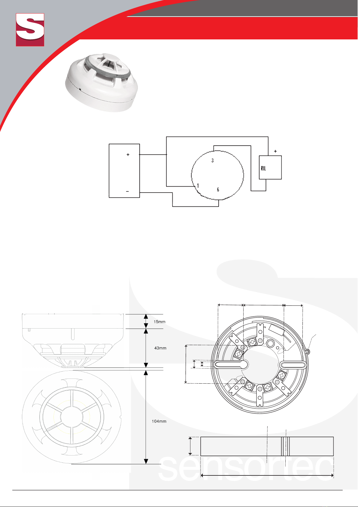
Section 11 – DIMENSIONS
8
If +ve supply derived from loop, RIL must be LED type
UB-4 / STB-4SE Bases
RIL must be 6v, 2mA max
Auxiliary terminal RIL current limited to 2mA. If the +ve supply for the auxiliary equipment is taken from the
loop, care must be taken to not cause corruption of the data protocol by excessive current draw.
27 mm
43 mm
20 mm
41 mm
4.5 mm
9 mm
2.8 x 6 mm
GRUB SCREW
15 mm
104.5 mm
27 mm
43 mm
20 mm
41 mm
4.5 mm
9 mm
2.8 x 6 mm
GRUB SCREW
15 mm
104.5 mm
Section 10 – CONNECTIONS

Technical Manual: ST-H2-AS (Changes are subject to DCRN)
sensortec
sensortec
Ref No: NISM/ST-H2-AS/02 Date: 03.02.20 Issue: 02
• sensortec • ST-H2-AS • analogue addressable heat sensor instruction manual
9
Section 12 - DISPOSAL
This symbol on the ST-H2-AS indicates that this product must not be
disposed of with household waste. Instead, it is your responsibility to
dispose of your waste equipment by handing it over to a designated
collection point for the recycling of waste electrical and electronic
equipment. The separate collection and recycling of your waste
equipment at the time of disposal will help to conserve natural resources
and ensure that it is recycled in a manner that protects human health
and the environment. For more information about where you can drop
off your waste equipment for recycling, please contact your local city
office or your household waste disposal service.
Section 13 - ROHS COMPLIANCE
STATEMENT
(RoHS compliant and lead-free)
This product complies with the European Union RoHS (Restriction of
Hazardous Substances) directive (EU) 2015/ 863 which restricts the
use of the following ten hazardous materials in the manufacture of
electronic and electrical equipment.
• Cadmium (Cd): < 100 ppm
• Lead (Pb): < 1000 ppm
• Mercury (Hg): < 1000 ppm
• Hexavalent Chromium (Cr VI): < 1000 ppm
• Polybrominated Biphenyls (PBB): < 1000 ppm
• Polybrominated Diphenyl Ethers (PBDE): < 1000 ppm
• Bis(2-Ethylhexyl) phthalate (DEHP): < 1000 ppm
• Benzyl butyl phthalate (BBP): < 1000 ppm
• Dibutyl phthalate (DBP): < 1000 ppm
• Diisobutyl phthalate (DIBP): < 1000 ppm
Table of contents


