INSTALLATION
Install the power pack and connect the load according to
its instructions.
Connect the low voltage wires of power pack with the
respective wires of the sensor according to the diagram
of desired control.
Turn ON the line voltage power for the power pack.
Conduct sensor operation test.
Attach the wallplate cover after testing and setting
completed.
1.
2.
3.
4.
5.
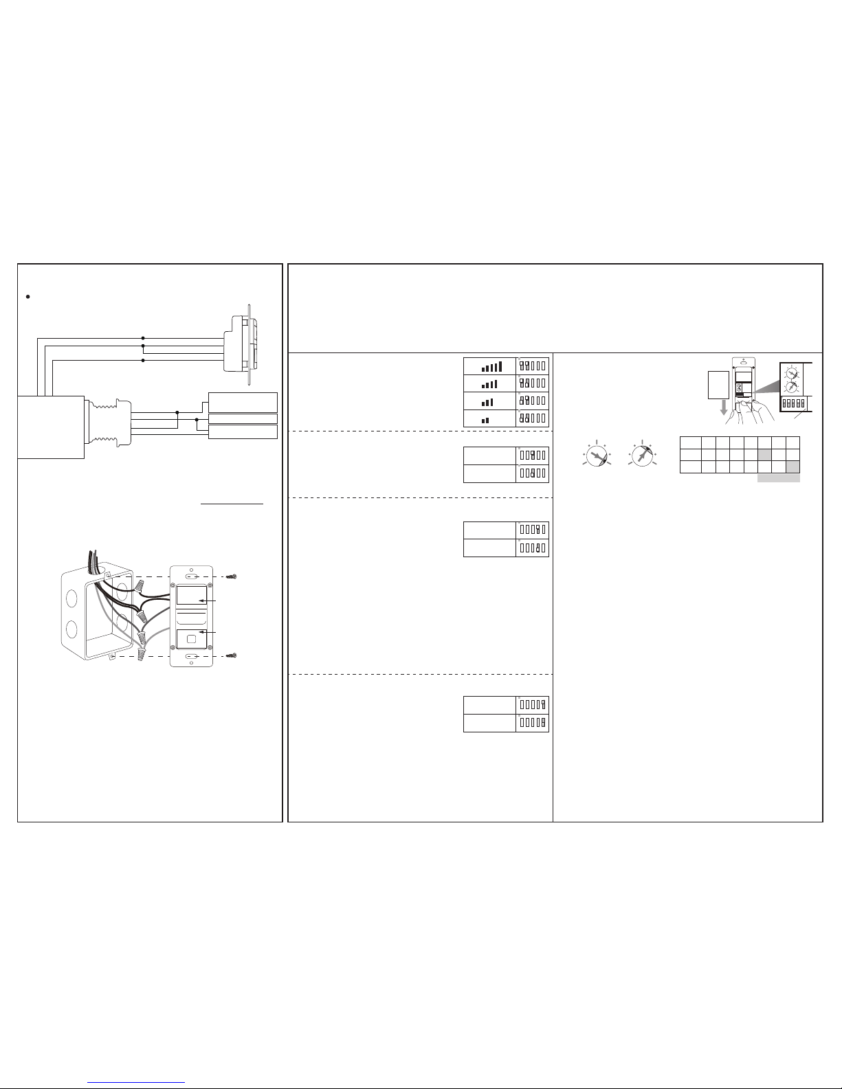
WIRING DIAGRAM
The sensor may be available with other control options,
for assistance.
Sensor control ON/OFF
Hot Black
White
Red
Red
Black
Green
White
Red
Black
Blue
Red
Neut
Relay
Relay
DC24V
GND
Control
Manual
Hold ON
Hold OFF
Load
Hot
120~277V
Neutral
PPU-300/301
DC+
GND
COM
NO
(PPU-300/301)
OPERATION
The BDS-700 series low voltage dual-tech wall switch sensor
employs passive infrared (PIR) and High Frequency Doppler (HFD)
sensing technologies to monitor the occupancy status within
its coverage, and provide an isolated dry contact output for the
connected power pack to control the operation of connected load.
The BDS-700S also features ambient light sensor to inhibit
unnecessary lighting when ambient light is higher than the level set.
TIME setting determines the delay time that the sensor will
hold the load ON after the last motion detected. Factory
setting is 10 minutes, and it can be changed by pointing the
arrowhead of potentiometer to the specific position.
TIME - Delay time
LUX setting determines the threshold of ambient light level
that the sensor will inhibit switching ON the load. The factory
setting is ALS disabled (24 Hr) for testing convenience, and it
can be changed by pointing the arrowhead of potentiometer
to the specific position.
LUX – Ambient light level
TESTING
Restore the line power for sensor operation and wait for
the sensor to warm-up (GREEN LED will blink during the
warm-up period).
Move within the desired range and observe the sensor
detection. BLUE blink indicates the PIR sensor detected,
and GREEN blink indicates the HFD sensor detected.
Move outside of the desired range and observe if the HFD
sensor can detect. If GREEN LED blinks, reducing the HFD
sensitivity accordingly.
Replace the wall plate cover after sensor testing and setting
completed.
1.
2.
3.
NOTE: The connected load will be switched ON as delay time
set (factory default 10 minutes) after the power applied. The
delay time can be set to the shortest (10 seconds) for test
convenience. Ensure to set the TIME back to the desired
delay for optimum operation after test.
To program the sensor
operation mode or change
the settings, press the
push-button cover and slide
it down as shown.
SETTING - Potentiometer
The combinations of DIP switch 1 and
2 determines the sensitivity of HFD
sensor.
SETTING - DIP Switch
HFD Sensitivity - SW1 & 2
- SW3
- SW4
- SW5
DIP switch 3 changes the operating
sensor. If necessary, the BDS-700 can
be programmed as a single HFD wall
switch sensor.
Operating Sensor
Occupancy/Vacancy Sensor Selection
Push-button Operation Control
PIR & HFD
HFD only
ON
1 2 3 4 5
ON
1 2 3 4 5
ON
1 2 3 4 5
ON
1 2 3 4 5
Occupancy
Vacancy
ON
1 2 3 4 5
ON
1 2 3 4 5
ON/OFF
PM
Occupancy sensor switches the light
ON automatically when PIR sensor
detects the presence of an occupant.
The sensor will switch the light OFF
automatically if no occupant activity has been detected by
either PIR or HFD sensor before the time delay elapses.
Vacancy sensor requires the user to manually press the
push-button to turn ON the light. The sensor will switch the light
OFF automatically if no occupant activity has been detected by
either PIR or HFD sensor before the time delay elapses.
NOTE: The sensor will automatically turn ON the light if it
detects occupant activity within 30 seconds after time delay
elapsed.
Pressing the push-button during
occupied state will turn OFF the load of
respective pole and hold OFF until the
push-button is pressed again.
In Presentation Mode (PM), pressing the push-button will turn
OFF the lights immediately, and the lights will remain OFF even
if motion is detected. Pressing the push-button again will turn
the light ON and the sensor will operate per its settings. If the
time delay expires and no occupant activity has been detected,
the sensor will return to its normal operation. The lights will turn
ON with the next motion detected.
LUX
1 7
2 6
3 5
4
TIME
1 7
2 6
3 5
4
LUX
TIME T
POS. 1 2 3 4 5 6 7
1’ 3’ 5’ 10’ 20’ 30’
10 20 35 50
100 150 24H
Factory Set
Slide ON
1 2 3 4 5
TIME
LUX
Press
&
DIP
Switch
ON
1 2 3 4 5
TIME
LUX
ON
1 2 3 4 5
ON
1 2 3 4 5
ON
1 2 3 4 5
ON
1 2 3 4 5
LENS
PUSH-
BUTTON
The time delay (TIME) and ambient light level (LUX) settings can be changed
by rotating the respective Accu-Set potentiometer at different positions. Via
DIP switch setting, the BDS-700S can be programmed to adjust the HFD
sensitivity, operate as a single HFD wall switch sensor, control the load as an
Occupancy Sensor or Vacancy Sensor, and set the push-button operation to
turn ON/OFF manually or in Presentation Mode (PM).
To program the sensor operation mode or change the settings, press the
push-button cover and slide it down as shown.