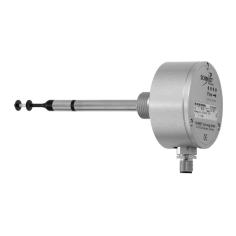
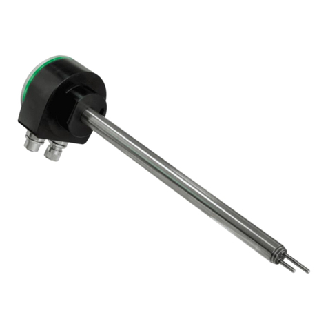
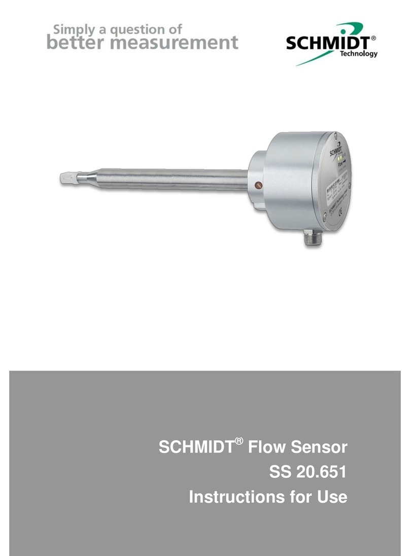
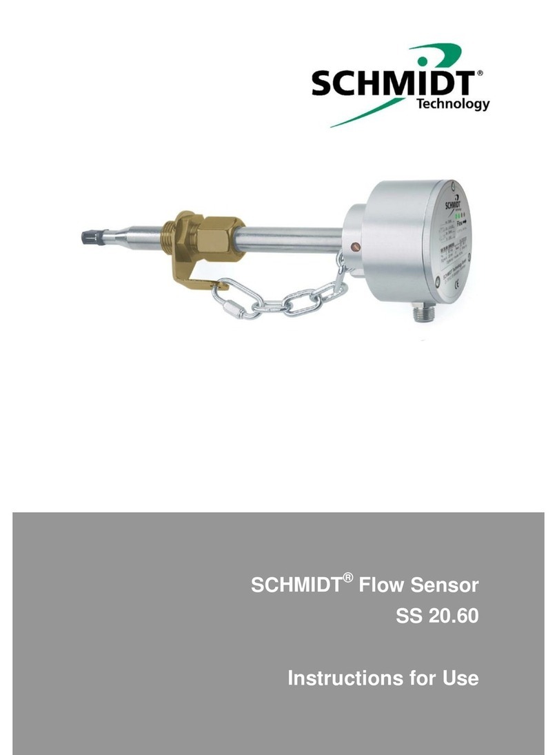
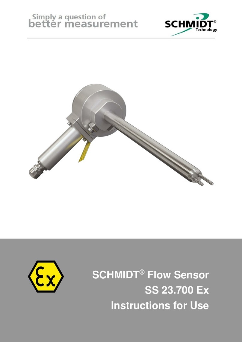
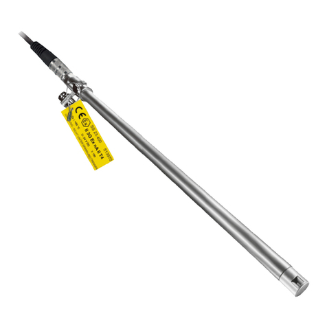
Schmidt SS 20.500 Ex User manual

SCHMIDT®Flow Sensor
SS 20.500 Ex
–Supplement for use ATEX
Instructions for Use

Instructions for Use SS 20.500 Ex –Supplement for use ATEX Page 2
SCHMIDT®Flow Sensor
SS 20.500 Ex –ATEX version
Table of Contents
1Important information.......................................................................3
2Transport and storage.....................................................................4
3Safety instructions for explosive atmospheres................................5
4Application range.............................................................................6
5Mounting instructions.......................................................................7
6Electrical connection and protective sleeve assembly....................9
7Type plate - Labeling.....................................................................11
8Declarations of conformity.............................................................12
9Type-examination certificate .........................................................13
Imprint:
Copyright 2021 SCHMIDT Technology GmbH
All rights reserved
Version 526488.02F
Errors and technical modifications subject to change

Instructions for Use SS 20.500 Ex –Supplement for use ATEX Page 3
1 Important information
The present instructions for use contain all ATEX specific information for
fast commissioning and safe operation of the version of SCHMIDT®Flow
Sensor SS20.500 Ex suitable for ATEX.
Please also read the "Instructions for Use SS 20.500“ (material no.:
523375.02) as the present instructions for use are supplementary in-
structions for use in explosive atmospheres.
These instructions for use must be read completely and observed care-
fully, before putting the unit into operation.
Any claims under the manufacturer's liability for damage resulting from
non-observanceor non-compliance with these instructions will become
void.
Tampering with the device in any way whatsoever - with the exception
of the designated use and the operations described in these instruc-
tions for use - will forfeit any warranty and exclude any liability.
The unit is designed exclusively for the use described below (see chap-
ter 4). In particular, it is not designed for direct or indirect protection of
personal and machinery.
SCHMIDT Technology cannot give any warranty as to its suitability for
certain purpose and cannot be held liable for accidental or sequential dam-
age in connection with the delivery, performance or use of this unit.
Other instructions for assembly, commissioning, maintenance and disas-
sembly can be found in the general instructions for use (material no.:
523375.02) of the SCHMIDT®Flow sensor SS 20.500.
Symbols used in this manual
The symbols used in this manual are explained in the following section.
Danger warnings and safety instructions - Read carefully!
Non-observance of these instructions may lead to injury of the
personnel or malfunction of the device.
Risk of explosion - Read carefully!
Important instructions for use in areas subject to explosion haz-
ards.
!

Instructions for Use SS 20.500 Ex –Supplement for use ATEX Page 4
2 Transport and storage
Packaging
The device is protected by its packaging. The packaging is environmen-
tally safe and recyclable. Basically, the following materials are used:
Cardboard box
Polyethylene film
Dispose available packaging parts by submitting it to a recycling company.
Conditions for transport and storage
The following points must be observed in order to prevent damage:
Do not expose the device to excessive mechanical load, such as throw-
ing, stacking, falling etc.
Do not use the device in environments where humidity and rain is pos-
sible.
Do not expose the device to direct sunlight for a long time.
Before transport or shipment of the sensor, the delivered protective cap
must be placed onto the sensor tip.
The storage temperature must not be lower than -40 °C or higher than
+85 °C.

Instructions for Use SS 20.500 Ex –Supplement for use ATEX Page 5
3 Safety instructions for explosive atmos-
pheres
The ATEX version SCHMIDT Flow Sensor SS 20.500 Ex is
only suitable for the following applications:
oIn explosive dust atmospheres: Zone 22
oIn explosive gas atmospheres: Zone 2
The important explosion protection data indicated on the label
of the product must be observed:
oG = Gas, D = Dust
oDevice categories 1, 2, 3 in the 3 zones
oGas specific values: Temperature class (T1 …T6)
oDust specific values:
-Conductive and not conductive
-Surface temperature with regard to smoldering temper-
ature (less 75 oC) and ignition temperature (2/3); the
smaller value applies
Prior to carry out operations such as assembly or electrical
connection, make sure that:
othe operation approval of the owner is available
othere is no explosive atmosphere
othe device is disconnected from the mains
othe device cannot be switched on inadvertently
Avoid dust deposits (installation position, protection, cleaning
measures…) in order to prevent dangerous increase of the
surface temperature.
Installation, commissioning and periodic checks must be car-
ried out by qualified personnel only ("qualified person“ ac-
cording to TRBS, Technical Rules for Operational Safety,
1203).
Repair work must be carried out by the manufacturer only.
Changes to the device are not allowed and can cause risk of
explosion (ignition).
Only original accessories from the manufacturer may be
used.

Instructions for Use SS 20.500 Ex –Supplement for use ATEX Page 6
The following standards and rules are useful:
oEN 1127-1: Explosion prevention and protection - Basic con-
cepts and methodology
oTRBS series
oStandards for explosive gas ("G") and dust atmospheres ("D"):
- EN 60079-14: Electrical apparatus for explosive atmospheres
- EN 60079-17: Inspection and maintenance
oStandards for explosive gas atmospheres ("G"):
- EN 60079-10-1: Classification of explosive gas atmospheres
oStandards for explosive dust atmospheres ("D"):
- EN 60079-10-2: Classification of explosive dust atmospheres
4 Application range
The ATEX version of the category 3 SCHMIDT®Flow sensor SS 20.500
Ex is designed for stationary measurement of the flow velocity as well as
the temperature of air or gas in potentially explosive atmospheres featur-
ing the following types of protection for:
oGases (Zone 2): II 3G Ex ec ic IIC T4 Gc
oDusts (Zone 22): II 3D Ex tc ic IIIC T135°C Dc
The sensor is suitable for use in atmospheres with combustible,
conductive dust with a smoldering temperature higher than 210 °C.
Special condition for use ("X"):
oThe main housing of the sensor may only be operated in an
area with a minimum degree of contamination 2, as defined in
IEC 60991-1.
oThis does not apply to the tube-shaped sensor probe (includ-
ing the connecting cable for the remote version).
The permissible operating temperatures are:
oElectronics : -20 ... +70 °C
oSensor probe: -40 ... +85 °C
Electrical datas:
oRated voltage : 24 VDC/AC ± 20 %
oRated current: 170 mA
oMeasurement outputs: 0 … 10 V / 4 … 20 mA
Enclosure:
oDegree of protecion: IP64
Instructions for Use SS 20.500 Ex –Supplement for use ATEX Page 7
5 Mounting instructions
Prior to the assembly in explosive atmospheres, the following safety
measures must be observed:
Check if the device category corresponds to the specified
zones.
Check if the operation approval from the owner is available.
Check if there is no explosive atmosphere during assembly,
maintenance or other activities.
Compliance with the applicable regulations and the entire rel-
evant documentation for this device.
ATEX relevant operating conditions
Pressure-tight accessories
Only use suitable, pressure-tight accessories if media separation
is required.
Observe pressure safety measures.
Opening of housing
It is not allowed to open the housing (sealed housing screws).
Unauthorized opening of the housing renders the explosion pro-
tection null and void!
Remote version
The connecting cable between sensor probe and main housing
includes intrinsically safe circuits. It is already connected ex
works and must not be disconnected or modified in any way.
Mounting ground or equipotential bonding conductor
The metallic enclosure of the sensor must be connected electrically to
grounding or equipotential bonding according to EN IEC 60079-0.
The cable required for this must be fastened at the terminal screw of the
enclosure, for the remote version also at the sensor probe.
In general the following applies to grounding:
The external ground connections of the enclosure must be con-
nected to the equipotential bonding of the hazardous area with
low ohmic resistance.
No equipotential current must flow between the hazardous
area and non-hazardous area.
Minimum cable cross-section: 1 x 4 mm2

Instructions for Use SS 20.500 Ex –Supplement for use ATEX Page 8
The screw must be tightened firmly at the terminal so that the
conductor cannot be loosened or twisted.
The potential difference between the GND of the operating
voltage and the grounding potential must be ≤ 30 VPeak 1.
Figure 5-1 Grounding contacts (red), remote version
Figure 5-2 Grounding contact (red), compact sensor
1
ESD protection via in-house varistor installed between GND and housing.

Instructions for Use SS 20.500 Ex –Supplement for use ATEX Page 9
6 Electrical connection and protective sleeve
assembly
Electrical connection is realized via a special connecting cable only avail-
able at SCHMIDT Technology that can be purchased as additional op-
tional accessory:
Material nos.: 523565 or 523566
Connecting cable
The sensor must be operated only with a original connecting ca-
ble by SCHMIDT Technology (optional accessory).
Otherwise, the ATEX suitability is null and void.
Connection on the sensor side is realized by means of a plug-in connector
which has to be protected against impacts and UV radiation by means of
a protective sleeve
2
. Latter features an ATEX-certified cable entry (1x
M12) and must be installed afterwards (see Figure 6-1).
Protective sleeve for plug-in connector
Must absolutely be mounted!
If the protective sleeve is not mounted professionally, the explo-
sion protection becomes null and void!
It is recommended to connect, first, the connecting cable on the field side
(before, fit protective sleeve on cable, see Figure 6-1).
Other electrical accessories, such as Zener barriers or intrinsically safe
power supplies, are not required for the ATEX operation.
In general the followings apply:
During electrical installation ensure that no voltage is applied
and inadvertent activation is not possible.
This applies in particular when disassembling the sensor.
WARNING!
DO NOT DISCONNECT THE CONNECTING CABLE AND
SENSOR WHEN THEY ARE UNDER VOLTAGE!
WARNING!
DO NOT OPEN PROTECTIVE SLEEVE UNDER VOLTAGE!
2
Included in delivery
!

Instructions for Use SS 20.500 Ex –Supplement for use ATEX Page 10
Figure 6-1 Assembly of connecting cable with protective sleeve
(1)
(3)
(2)
(4)
Cable
connection
Protective
sleeve
Sensor plug
Fastening screw of
protective sleeve
(with snap ring)
Nut of cable
bushing
(M12, 7 Nm)

Instructions for Use SS 20.500 Ex –Supplement for use ATEX Page 11
Assembly (see Figure 6-1):
(1) Insert open end of connecting cable into protective sleeve (un-
screw the screw of cable bushing) and push latter until almost
touching the cable connector.
(2) Insert cable connector into plug of the sensor housing and tighten
spigot nut by hand.
(3) Push protective sleeve over plug-in connector and fasten it with
the included screws (hexagon sockets 2.5 mm; don’t forget snap
rings) to the housing (tighten by hand).
(4) Tight nut of cable bushing (M12, 7 Nm).
7 Type plate - Labeling
The rating plate for labeling according to the standards is fixed at the sen-
sor by means of a wire loop.
If required, the customer can attach this plate on or at the sensor on his
own responsibility provided that it can be clearly assigned to the sensor
and is legible and undetachably. Examples are:
Mounting it directly at the sensor, e.g. with a machine screw
through the loop hole.
Mounting it undetachably onto a near wall according to
EN IEC 60079-0, chapter 29.6.
The side with the warning note
"Do not disconnect under voltage"
must remain visible.

Instructions for Use SS 20.500 Ex –Supplement for use ATEX Page 12
8 Declarations of conformity
SCHMIDT Technology GmbH herewith declares in its sole responsibility,
that the product
SCHMIDTFlow Sensor SS 20.500 Ex
Part-No. 521 501 (configuration code: X Y Z P 2)
is in compliance with the appropriate
European guidelines and standards
and
UK statutory requirements and designated standards.
The corresponding declarations of conformity can be download from
SCHMIDT®homepage:
www.schmidt-sensors.com
www.schmidttechnology.de

Instructions for Use SS 20.500 Ex –Supplement for use ATEX Page 13
9 Type-examination certificate

Instructions for Use SS 20.500 Ex –Supplement for use ATEX Page 14

Instructions for Use SS 20.500 Ex –Supplement for use ATEX Page 15

Instructions for Use SS 20.500 Ex –Supplement for use ATEX Page 16
SCHMIDT Technology GmbH
Feldbergstraße 1
78112 St. Georgen
Germany
Phone +49 (0)7724 / 899-0
Fax +49 (0)7724 / 899-101
Email sensors@schmidttechnology.de
URL www.schmidt-sensors.com
www.schmidttechnology.de
Table of contents
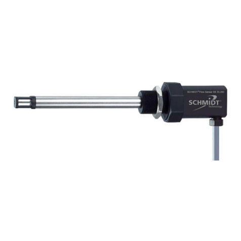
Other Schmidt Accessories manuals

Schmidt
Schmidt SS 20.600 User manual

Schmidt
Schmidt SS 20.500 User manual

Schmidt
Schmidt SS 20.600 User manual

Schmidt
Schmidt SS 20.260 User manual

Schmidt
Schmidt SS 20.700 User manual

Schmidt
Schmidt SS 20.225 User manual

Schmidt
Schmidt SS 20.700 User manual

Schmidt
Schmidt SS 20.60 User manual

Schmidt
Schmidt SS 23.700 Ex User manual

Schmidt
Schmidt SS 20.515 LED User manual
Popular Accessories manuals by other brands

NuTone
NuTone C905 Installation instructions manual

Promate
Promate EnergyMate user guide

Vega
Vega VEGAFLEX 82 operating instructions

Rice Lake
Rice Lake 1280 Enterprise Series Operation manual

PCB Piezotronics
PCB Piezotronics 123B21 Installation and operating manual

Allen-Bradley
Allen-Bradley Photoswitch ColorSight 9000 Series user manual