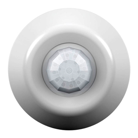
SENSORWORX SWX-201-2 Installation instructions

LINE VOLTAGE
CEILING MOUNT SENSORS
INSTALLATION & OPERATION INSTRUCTIONS
OVERVIEW
SENSORWORX line voltage sensors detect movement in the infrared energy that
radiates from occupants as they move within the devices eld-of-view. Once occupancy
is identied the sensor’s internal relay switches power on to the connected lighting. If
equipped with passive dual technology (PIR/Acoustic), the unit’s microphone is then also
enabled to further enhance detection while the lights are on. This overlapping passive
acoustic occupancy detection is important for rooms with obstructions or where occupant
motion will be limited. An internal timer is set to keep lights on during brief periods of
inactivity, and is reset every time occupancy is signaled by either the passive infrared
or acoustic detection technologies. Additionally, units equipped with ambient daylight
detection (photocells) are capable of overriding lights off during periods of occupancy.
FEATURES
Digital Passive Infrared (PIR)
Detection
Passive Acoustic Detection
(Optional)
360° Coverage Pattern
Compact Size and Matte Finish
Convenient Test Mode and
Adjustable Time Delays
Ambient Daylight Detection
(Optional)
SPECIFICATIONS
ELECTRICAL
OPERATING VOLTAGE
MVOLT (120-277 VAC)
LOAD RATINGS
800W @ 120 VAC
1200W @ 277 VAC
LOAD TYPES
Tungsten
Ballast
LED
PHYSICAL
SIZE
4.00” Diameter x 1.25” H
(10.16 x 3.17 cm)
WEIGHT
4.75 oz
COLOR
White
ENVIRONMENTAL
OPERATING TEMP
-10°F to 122°F (14°C to 50°C)
RELATIVE HUMIDITY
0-95% Non-Condensing,
Indoor Use Only
OPERATION
TIME DELAYS
30 sec to 30 min
10 Minute Default
TEST MODE
5 sec
CODE COMPLIANCE
Sensors can be used to meet
ASHRAE 90.1, IECC, & Title 24
energy code requirements
OTHER
LISTINGS
UL/CUL
SENSOR PLACEMENT
Typically, a sensor should be located such that all entrances to the room/space are
adequately covered. Ideally, a sensor should be located so that its coverage beams are
perpendicular to the door. This ensure that an occupant is detected immediately upon
entering. See Diagram 1. Note, however, it is important to locate a sensor such that its
coverage pattern can not extend through an open door, which could result in detection of
persons walking by, but not into, a room.
If line of sight between a sensor and occupants is blocked (for example by a cubicle
wall or stall), dual technology sensors should be alternatively utilized or additional PIR
sensors should be added until line of sight is restored. Dual technology is recommended
for all spaces where occupants are sitting or where motion within the space is limited
(private ofces, open ofces, restrooms with stalls, libraries). Dual technology is not
recommended for hallways or warehouses.
1:48 Scale = 2.1%
10’ x 11’ SINGLE OFFICE
Diagram 1 - Recommended Sensor Placement in a Private Ofce
MODEL # PIR ACOUSTIC PHOTOCELL LENS TYPE
SWX-201-2 •SMALL MOTION
SWX-211-2 • • SMALL MOTION
SWX-221-2 • • SMALL MOTION
SWX-231-2 • • • SMALL MOTION
SWX-202-2 •LARGE MOTION
SWX-212-2 • • LARGE MOTION
SWX-222-2 • • LARGE MOTION
SWX-232-2 • • • LARGE MOTION
*Additional options include: HE: Humid Environment

12
6
0 ft
6
12
3.7
1.8
0 m
1.8
3.7
TOP VIEW
8 ft Mount
0 ft 0 m
82.4
12 3.7
SIDE VIEW
0 ft
0 m
5
1.5
5
1.5
10
3
10
3
15
4.6
15
4.6
20
6.1
20
6.1
28
14
0 ft
14
28
8.5
4.3
0 m
4.3
8.5
TOP VIEW
8 ft Mount
0 ft 0 m
82.4
12 3.7
15 4.6
SIDE VIEW
0 ft
0 m
10
3
10
3
20
6.1
20
6.1
30
9.1
30
9.1
40
12.2
40
12.2
COVERAGE
PASSIVE INFRARED (PIR)
8 to 15 ft (2.44 to 4.57 m) mounting height recommended
Detection range improves when walking across beams as compared to into beams
Lenses can be swapped in eld if necessary, contact technical support for assistance
DUAL TECHNOLOGY (PIR/ACOUSTIC)
Units with dual technology (SWX-221-2 and SWX-222-2) have overlapping acoustic detection of the complete PIR coverage area
A PIR event is required to initially enable Acoustic detection
Sounds indicating occupancy reset the sensor’s time delay while non-occupant noises are ltered out
Occupant sounds alone will not keep lights on indenitely, PIR motion must be periodically detected for lights to remain on for an extended time
After sensor time out expires, acoustic detection remains enabled for 10 seconds to enable voice reactivation of lights for additional convenience and safety
LARGE MOTION 360°
Best choice for detection of larger motion (e.g., walking)
~2000 ft2of coverage
Longest segment of coverage pattern aligns with screw hole axis on sensor
(shown as dotted line on Top View diagram below)
SMALL MOTION 360°
Best choice for detection of small motions from sitting occupants
(e.g., hand motion)
~500 ft2of coverage
PHOTOCELL OPERATION
Sensors with an integrated photocell will turn lights on/off depending on the amount of ambient light detected. This operation makes them ideal for lighting near skylights or windows.
WIRING
BLK
BLK
WHT
N
120V-
277V
NEUTRAL
SWITCHED HOT
SWITCH
LOAD
SWX
LINE VOLTAGE
SENSOR
Sensors can be wired in parallel, although the total switching load remains the same.
When wired in parallel, both sensors must time out for connected lighting to turn off.
WARNING: TURN POWER OFF AT THE CIRCUIT BREAKER BEFORE WIRING
INSTALLATION NOTES
For supply connections, use wires rated for at least 75°C or equivalent.

INSTALLATION INSTRUCTIONS
PROGRAMMING
BUTTON
MUDRING
4” JUNCTION BOX
SIDEFRONT
SENSOR
SENSOR
COVER
SCREW HOLES FOR DIRECTLY MOUNTING TO:
• CEILING SURFACE
• 3-1/2” (TRADE SIZE) OCTAGON BOX
• MUD RING WITH 2-3/4" SPACED EARS
SENSOR MOUNTED
DIRECTLY TO
3.5” TRADE SIZE
OCTAGON BOX
Designed to mount to a mud ring w/ 2.75” spaced ears, screws provided
Also ts a 3.5” trade size octagon box
Use model #SWX-299 trim ring to mount sensor directly to a 4.0” octagon box, handy box, or to a single
gang mudring.
TESTING & TROUBLESHOOTING
TEST MODE
A test mode with a 5 second time delay is provided in order to efciently perform walk
testing. The sensor will blink White on any detected occupancy (PIR or Acoustic), although
its time delay will only be reset by a PIR event. Note that while in test mode all LED
activity related to ambient light override (photocell) functionality is overridden.
TO PUT A SENSOR IN TEST MODE FOR 10 MINUTES:
Press sensor’s pushbutton 2 times, then wait two seconds
Press button 1 time to start test mode. After 10 minutes, the sensor’s time delay will
revert to previous setting
AMBIENT LIGHT OVERRIDE
Do not mount sensor such that it is directly viewing into the lights it is controlling. This
will cause the measured level of controlled/articial light to be extremely high, thus
preventing the sensor from ever turning lights off from ambient light.
RESET
To restore factory settings, press and release the pushbutton 8 times, wait 2 seconds,
then press and release the pushbutton 3 times again.

MICROPHONE
Dual technology sensors prevent non-occupant sounds from resetting the time delay
by dynamically reducing the microphones sensitivity at specic frequencies. In some
environments, decreasing the sensitivity across all frequencies so that lights go off
sooner, may be preferred. A unit’s microphone can also be disabled (effectively changing
sensor to a PIR only version).
TO CHANGE MICROPHONE SETTINGS:
1. Press unit’s pushbutton 6 times, then wait two seconds. The White LED will blink back
the number of current setting (from table on right).
2. At any time after blink back starts, enter number of new setting by pressing the button
equal times to choice from table.
3. New setting will be saved after White LED blinks back new number 3 times. If Blue
LED double ashes at any time, start process over.
FUNCTION #6 - MICROPHONE
SETTING # DESCRIPTION
2 Normal Operation [Default]
3 Reduced Sensitivity
4 Disabled
CONFIGURATION SETTINGS
TIME DELAY CONFIGURATION
1. Read through the Time Delay Settings list and note the number of the
desired time delay setting (e.g., default is 4 = 10 minutes)
2. Press and release the unit’s pushbutton twice, then wait 2 seconds.
The White LED will blink back the number of the current setting
3. At any time after blink back starts, enter number of new setting
(from Time Delay Settings table on right)
4. New setting is saved after White LED blinks new number back 3 times.
If Blue LED double ashes at any time, start process over
FUNCTION #2 - TIME DELAY SETTINGS
SETTING # DESCRIPTION
1 Test Mode**
2 30 sec
3 5 min
4 10 min [Default]
5 15 min
6 20 min
7 30 min
** 5 SEC TIME DELAY, EXPIRES AFTER 10 MIN
OPERATION MODE CONFIGURATION
To disable the operation of the photocell (in equipped units), use the following procedure:
1. Press and release the unit’s pushbutton 3 times, then wait 2 seconds. The White LED
will blink back the number of the current setting.
3. At any time after blink back starts, enter number of new setting from table on right
(e.g., 2 for OCCUPANCY - ON/OFF) from OPERATIONAL MODES table.
4. New setting is saved after White LED blinks back new number 3 times. If Blue LED
double ashes at any time, an error condition exists and process must be repeated.
FUNCTION #3 - OPERATIONAL MODES
SETTING # DESCRIPTION MODEL # NOTES
2 Occupancy - On/Off Default for SWX-20x-2 & SWX-22x-2
3Occupancy + Ambient Light Override
(Photocell) Default for SWX-21x-2 & SWX-23x-2
LED INDICATION
By default, the sensor blinks its White LED whenever it detects PIR motion. A unit with
dual technology will also blink the LED white when it acoustically detects occupancy. The
intensity of this LED can be increased or disabled. Additionally, the LED can be enabled to
blink white for only PIR events and blue for an acoustic event.
TO CHANGE LED INDICATION SETTINGS:
1. Press unit’s pushbutton 7 times, then wait two seconds. The White LED will blink back
the number of current setting (from table on right).
2. At any time after blink back starts, enter new setting by pressing the button equal
times to numbered choices.
3. New setting will be saved after White LED blinks back new number 3 times. If Blue
LED double ashes at any time, start process over.
SETTING # DESCRIPTION
2 White LED for all occupancy, normal brightness [Default]
3 White LED for all occupancy, increased brightness
4 Disable LED
5 White LED for PIR, Blue for Acoustic, normal brightness
6 White LED for PIR, Blue for Acoustic, increased brightness

Five-Year Limited Warranty.
Complete Warranty Terms Located at: sensorworx.com/warranty
INS200-2 | REV 001–190228
SENSORWORX | 3 Essex Sq, Essex, CT 06426
203.678.4224 | www.sensorworx.com
© 2019 BLP Technologies, Inc. All rights reserved.
AMBIENT LIGHT OVERRIDE (PHOTOCELL) OPERATION
During periods of occupancy, sensors with an integrated photocell (models SWX-21x-2,
SWX-23x-2) will turn lights on/off depending on the amount of ambient light detected.
This operation makes them ideal for lighting in daylight zones (i.e. near windows). Lights
will turn off when the measured light level is high enough for 5 min. such that turning the
lights off will not drop the level below the selected setpoint. During this 5 min. transition
time the LED will blink blue at 0.5 second intervals. After lights are turned off, the
sensor’s LED double blinks blue every 15 seconds as an indication that sufcient ambient
light is the reason the lights are being held off. If the ambient light level falls below the
setpoint for more than 30 seconds, lights will switch back on. During this transition time
the LED also will blink blue at 0.5 second intervals.
CONFIGURATION SETTINGS CONT.
PHOTOCELL SETPOINT
The minimum overall light level that is to be maintained in a space by the sensor is
referred to as the “setpoint”. This value is user selectable or can be chosen by the Auto-
Setpoint function that is built into the sensor.
SETPOINT CONFIGURATION
1. Read through the below setpoint values list and note the number of the desired
setpoint (e.g., default is 7 = 25 fc).
2. Press and release the unit’s pushbutton 4 times, then wait 2 seconds. The White LED
will blink back the number of the current setting.*
3. At any time after blinking starts, enter number of new setting (from Setpoint Value
Table).
4. New setting is saved after White LED blinks new setting back 3 times. If Blue LED
double ashes at any time, an error condition exists and process must be repeated.
FUNCTION #4 - SETPOINT VALUE TABLE
SETTING # DESCRIPTION
2Run Auto-Setpoint*
32.5 fc
45.0 fc
510.0 fc
615.0 fc
725 fc (default)
835 fc
950 fc
*If Auto-Setpoint has been previously run, the value will be blinked back in two alternating digits:
Blue LED = 10’s digit (1-9 blinks or rapid blink or 0)
White LED = 1’s digit (1-9 blinks or rapid blink or 0)
*AUTO-SETPOINT SELECTION DETAILS
AOnce setting 2 “Run Auto-Setpoint” has been selected (by following above steps 1-4),
the sensor’s LED will alternate blue and white for 30 seconds. During this time user
should move away from sensor.
BLights will then be cycled in order for sensor to calculate the controlled (articial) light
level. This is done by subtracting the light level with the lights off (relay open) from the
light level with the lights on (relay closed).
CA setpoint will then be chosen using the following conditions:
If controlled level is less than 3 fc, the application is considered open loop and
the setpoint will be set to 50% of the measured level with the relay closed (plus a
margin to prevent cycling). Setting will be between 0.5 fc and 44 fc.
If controlled level is between 3 and 50 fc, setpoint will be set to that level times
1.25.
If controlled level is greater than 50 fc the setpoint will be set to 50 fc.
DUnit will immediately start operating with new setpoint (i.e. blue LED may begin
ashing indicating it will transition lights soon)
ETo check auto selected setpoint, press and release button 4 times. Setpoint will be
blinked back in two alternating digits:
Blue LED = 10’s digit (1-9 blinks or rapid blink or 0)
White LED = 1’s digit (1-9 blinks or rapid blink or 0)
Manual Setpoint Options
}
This manual suits for next models
7
Table of contents
Other SENSORWORX Accessories manuals
Popular Accessories manuals by other brands
Gibson
Gibson G FORCE owner's manual
Buhler
Buhler PKE 511 Installation and operation instruction
Kasanova
Kasanova Bell'aria MAS020948 instruction manual
Balluff
Balluff BUS M12E0-PPXCR-020-S04G Technical data

Craftsman
Craftsman ASF 486.246213 owner's manual

Yekbee
Yekbee iPad Folio Keyboard Case user manual
