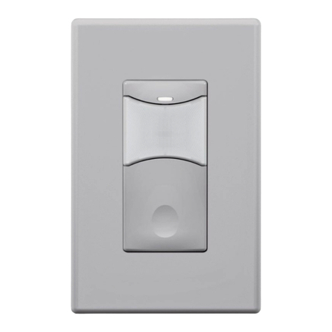
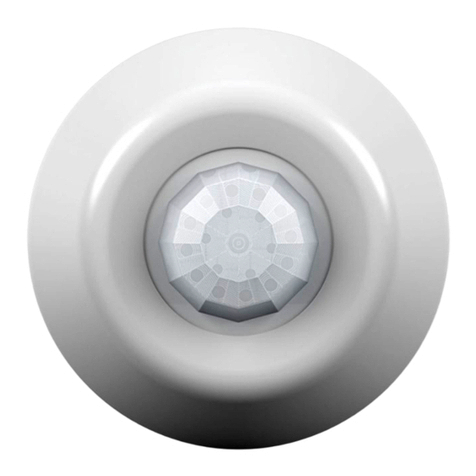
SENSORWORX SWX-101-D Series Installation instructions

LINE VOLTAGE
WALL SWITCH SENSORS
w/ 0-10V DIMMING
INSTALLATION & OPERATION INSTRUCTIONS
MODEL # PIR ACOUSTIC PHOTOCELL DEFAULT MODE
SWX-101-D-xx* •OCC
SWX-103-D-xx •VAC
SWX-104-D-xx •VAC
SWX-111-D-xx • • OCC
SWX-113-D-xx • • VAC
SWX-121-D-xx • • OCC
SWX-123-D-xx • • VAC
SWX-124-D-xx • • VAC
SWX-131-D-xx • • • OCC
SWX-133-D-xx • • • VAC
* XX = COLOR (WH, IV, AL)
OVERVIEW
SENSORWORX wall switch sensors detect movement in the infrared energy that
radiates from occupants as they move within the devices eld-of-view. Once occupancy
is identied, the sensor’s internal relay switches power on to the connected lighting.
Units can also be congured to operate in Vacancy Mode (e.g., require lights be manually
switched on). Once lights are on and if equipped with passive dual technology (PIR/
Acoustic), the unit’s microphone is enabled to further enhance detection. An internal timer
is set to keep lights on during brief periods of inactivity and is reset every time occupancy
is signaled by either the passive infrared or acoustic detection technologies. Ambient
daylight detection can also be enabled in the unit so that lights are held off in rooms with
sufcient light contribution from windows or skylights.
SPECIFICATIONS
ELECTRICAL
OPERATING VOLTAGE
120/277 VAC, 50/60 Hz
LOAD RATINGS
MAX: 800W @ 120VAC
1200W @ 277VAC
MIN: None
LOAD TYPES
LED Driver/Lamps
CFL, Electronic/Magnetic Ballasts
(Fluorescent)
Tungsten (Incandescent)
DIMMING CAPABILITY
0-10 VDC ballasts or drivers compliant
with IEC 60929 Annex E.2
DIMMING LOAD
- 50 mA (sink only)
PHYSICAL
SIZE
2.74”H x 1.68”W x 1.39”D
(6.96 x 4.27 x 3.53 cm)
Not Including Mounting Strap
WEIGHT
4.5 oz
MOUNTING
Single Gang Switch Box
ENVIRONMENTAL
OPERATING TEMP
32°F to 122°F (0°C to 50°C)
RELATIVE HUMIDITY
0-95% Non-Condensing,
Indoor Use Only
CODE COMPLIANCE
Wall Switch sensors can be used to
meet many requirements of ASHRAE
90.1(2016), IECC (2015), and Title 24
(2016). In particular, Manual On
(e.g., Vacancy) operation is prescribed
for many building spaces.
FEATURES
ELECTRICAL FEATURES
Interchangeable Line & Load Wires -
Impossible to Wire Backwards
Accommodates Neutral (3-wire)
and No-Neutral (2-Wire) Installation
Electronically Timed Switching
Ensures Long Relay Life
Compatible with LED, Fluorescent
and Incandescent Lighting
Meets NEC Guidelines Regarding
Current Leakage
PHYSICAL FEATURES
Enclosure is 25-40% Shallower than
Other Sensors (< 1” depth into wallbox)
Unique Bat-Wing Shaped Lens Provides
Enhanced Peripheral Detection
Self-Grounding Mounting Strap
Modern Look and Intuitive
Easy-Tap Button for On/Off, Raise, & Lower
Rugged Vandal Resistant Lens
Settings are Adjustable Without Removing
Cover Plate
OPERATIONAL FEATURES
Wall-To-Wall Passive Infrared
Small Motion Detection
Passive Acoustic Detection (Optional) -
Prevents False Offs when No Motion is Present
100% Passive Detection Methods -
No Interference Potential from External Devices
Congurable Dimming Parameters including
High/Low Trims, Turn on Levels, and Curve Types
Ambient Daylight Override Mode Increases
Energy Savings
Blue Locator LED when Ligths are Off

BLK
WHT
BLK
NH
GRN
* NEUTRAL CONNECTION IS OPTIONAL,CAP IF UNUSED
*
0-10V DIMMING +
0-10V DIMMING –
GRY
VIO
0-10V DIMMABLE LOAD
SWX
WALL SWITCH
SENSOR
w/ DIMMING
WALL SWITCH
0 ft 0 m
41.2
SIDE VIEW
0 ft
0 m
10
3.0
20
6.1
30
9.1
40
12.2
TOP VIEW
4 ft Mount
4012.1
4012.1
206.1
0 ft0 m
206.1
COVERAGE
30” to 48’ (0.76 - 1.22 m) recommended mounting height
Wall to wall (~180 degree) coverage
Small motion (e.g., hand movement) detection up to 20 ft (6.10 m), ~625 ft2
Large motion (e.g., walking) detection greater than 36 ft (10.97 m), ~ 2025 ft2
Overlapping acoustic detection of occupants over entire coverage area
Advanced signal processing lters out nuisance noises while not effecting
overall sensitivity
As an added safety convenience, the acoustic detection is left active for
10 seconds after sensor turns the lights off to allow for voice reactivation
3-WAY WIRING
TWO SENSORS IN PARALLEL
Only one sensor can be model with 0-10V Dimming
Both sensors must time out for lights to turn off (or both buttons must be switched)
Recommended for Automatic On (Occupancy) applications only
INSTALLATION
STANDARD WIRING
WARNING: TURN POWER OFF AT THE CIRCUIT BREAKER BEFORE WIRING
* NEUTRAL CONNECTION IS OPTIONAL, CAP IF UNUSED
* NEUTRAL CONNECTION IS OPTIONAL, CAP IF UNUSED
WIRING
For supply connections, use 14 AWG (90° C) or larger wires
Risk of Electric Shock - more than one disconnect switch may be required
to de-energize the equipment before servicing
It is recommended that wiring the unit’s ground connection be done rst.
Unit works both in installations where Neutral connection is available as
well as installations where only Ground connection is present
The unit’s two black wires are interchangeable (e.g., one connects to line
power, one connects to load)
After wiring and mounting, install wall plate (not included) before turning
back on power at the circuit breaker
0-10V DIMMING +
0-10V DIMMING –
GRY
VIO
BLK
WHT
LOAD
BLK
N
SWX
WALL SWITCH
SENSOR
H
GRN
BLK
WHT
BLK
NN
SWX
WALL SWITCH
SENSOR
H
GRN
BLK
WHT
BLK
SWX
WALL SWITCH
SENSOR
w/ DIMMING
N
GRN
BLK
WHT
BLK
N
SWX
WALL SWITCH
SENSOR
GRN
Standard Wiring
3-Way Wiring
H
1-Sensor: 3-Way Wiring
3-WAY SWITCH
COMMON
TRAVELERS
TRAVELERS
LOAD
* NEUTRAL CONNECTION IS OPTIONAL,CAP IF UNUSED
*
**
*
* NEUTRAL CONNECTION IS OPTIONAL,CAP IF UNUSED
* NEUTRAL CONNECTION IS OPTIONAL,CAP IF UNUSED
0-10V DIMMABLE LOAD

INSTALLATION CONT.
MOUNTING
Designed to mount in 1-gang wall box with 3.28” hole spacing
Units also can share multiple gang wall boxes with other devices
** SENSOR FACE IS FIELD REMOVABLE IN ORDER TO CHANGE COLORS. CONTACT FACTORY FOR ADDITIONAL FACES
FRONT SIDE
SUPPLIED MOUNTING SCREWS
FOR MOUNTING TO
SINGLE GANG SWITCH BOX
1.39”
0.94”
KEY INSTALLATION
FEATURE
25-40% SHALLOWER
THAN OTHER WALL
SWITCH SENSORS
BREAK-OFF
BRACKET EARS
BREAK-OFF
BRACKET EARS
LED INDICATOR
RAISE
ON/OFF BUTTON
LOWER
SENSOR FACE**
2.74”
1.69”
** SENSOR FACE IS FIELD REMOVABLE IN ORDER TO CHANGE COLORS. CONTACT FACTORY FOR ADDITIONAL FACES
DIMMING APPLICATION TABLE
MODEL # DETECTION TYPE DEFAULT OPERATING MODE 1,2
PIR ACOUSTIC NAME DESCRIPTION
SWX-101-D •Partial On Auto-On to 50%
SWX-103-D •Vacancy Manual On to Last Level
SWX-111-D •Partial On Auto-On to 50%
SWX-121-D • • Partial On Auto-On to 50%
SWX-123-D • • Vacancy Manual On to Last Level
SWX-131-D • • Partial On Auto-On to 50%
1. ALL MODES ARE ENERGY CODE COMPLIANT
2. MODES ON ALL UNITS ARE FIELD CONFIGURABLE
DIMMING APPLICATION OVERVIEW

CENTER BUTTON
FUNCTION NAME BUTTON POSITION FUNCTION #
Time Delay Center 2
Operating Mode Center 3
Photocell Setpoint Center 4
Auto-on Sensitivity Center 5
Microphone Center 6
LED Center 7
Factory Reset Center 8
LEFT BUTTON
DIMMING
FUNCTION NAME BUTTON POSITION FUNCTION #
Turn Off Scheme Left 2
Low Trim Left 3
Fade Off Time Left 4
RIGHT BUTTON
DIMMING
FUNCTION NAME BUTTON POSITION FUNCTION #
Turn On Dimming Level Right 2
High Trim Right 3
Fade On Time Right 4
Dimming Curve Type Right 5
CONFIGURATION SETTINGS
CONFIGURATION PROGRAMMING
1From the lists of Conguration Functions below, note the Button Position and number (#) of the Function to be changed. For example, HIGH TRIM setting is the Right Button, #3.
2Enter programming mode by pressing and holding the CENTER button until the blue LED begins rapid ashing.
3Press and release the applicable button for the chosen function. For example, press the RIGHT button 3 times for the HIGH TRIM setting.
4The LED will ash back the setting number of the current value as it appears in each function’s detailed table of values. For example, the default HIGH TRIM is setting #2 (10V) for the
RIGHT button.
5Press and release the applicable button the number of times equal to the new setting #. For example, RIGHT button 3 times (for 9V).
6The LED will ash back the new setting number as conrmation.
7To exit programming mode, press and hold the function’s applicable button again until the LED ashes rapidly. The LED will then blink white twice as conrmation of success.
NOTE IF THE LED DOUBLE FLASHES TWICE BLUE AT ANY POINT, REPEAT THE ABOVE PROCEDURE.
CONFIGURATION FUNCTIONS
LED INDICATOR

CONFIGURATION SETTINGS CONT.
DETAILED FUNCTION TABLES FOR NON-DIMMING FEATURES
FUNCTION #2 TIME DELAY
CENTER BUTTON
SETTING # DESCRIPTION FUNCTION #
1 Test Mode Temporary 5 sec time delay, reverts after 10 min
2 30 Sec
3 5 Min
4 10 Min Default for all models
5 15 Min
6 20 Min
7 30 Min
FUNCTION #3 OPERATIONAL MODES
CENTER BUTTON
Several pre-programmed operational modes are available to accommodate both
preferences and applicable energy codes.
SETTING # DESCRIPTION NOTES
2
Vacancy Mode (Manual On / Automatic Off)
This mode provides increased energy savings but
requires the user to initially turn on the lights by
pressing the button. Lights can also be switched off
manually.
Default for models
SWX-1x3-D and
SWX-1x4-D.
3
Occupancy Mode (Automatic On / Automatic Off)
Automatic On and Automatic Off operation. If lights are
switched off manually, the Automatic On functionality
is temporarily disabled to allow the occupant a
few seconds to leave the room before returning to
Automatic On operation. However, if the person
remains in the space, the unit will stay in a manual on
state until the switch is pressed again.
Default for SWX-1x1-D
models. Not available
for SWX-1x4-D models.
4
Automatic On w/ Exit Time Mode (Automatic On/
Automatic Off)
If lights are switched off manually, the Automatic On
functionality is disabled for a xed 30 seconds to allow
a person time to leave the room.
Not available for SWX-
1x4-D models.
5
Override Off Mode
Automatic On and Automatic Off operation until lights
are switched off manually, at which point Automatic
On functionality is disabled until the button is pressed
again.
6
Disabled Switch Mode
Automatic On and Automatic Off operation only. Switch
functionality to manually turn on/off lights is disabled.
7
Presentation Mode
If lights are switched off manually, the Automatic
On functionality is disabled until the space becomes
unoccupied and the sensor’s time delay expires.
FUNCTION #5 AUTO ON SENSITIVITY
CENTER BUTTON
This setting indicates the sensor’s PIR sensitivity when the lights are off. Typically, this
setting should be FULL, but if reective surfaces (like windows) are causing false-ons the
REDUCED setting should be used. Note that the unit returns to full sensitivity after initial
detection.
SETTING # DESCRIPTION NOTES
2 Full initial PIR sensitivity Default for all models
3
Reduced PIR sensitivity for initial turn-ons in order to
eliminate false on’s caused by reective surfaces like
windows. Full sensitivity after initial turn-on.
FUNCTION #6 INITIAL ACOUSTIC SENSITIVITY
CENTER BUTTON
Dual technology (i.e. PIR + acoustic) sensors prevent non-occupant sounds from
resetting the time delay by dynamically reducing the microphone’s sensitivity at specic
frequencies. In some environments, decreasing the sensitivity across all frequencies so
that lights go off sooner, may be preferred. A unit’s microphone can also be disabled
(effectively changing sensor to a PIR only version).
SETTING # DESCRIPTION NOTES
2 Normal Default for all models
3 Reduced
4 Disabled
FUNCTION #7 LED FUNCTION
CENTER BUTTON
By default, the sensor’s LED will be solid blue when the unit’s relay is in the open/ off
state. This serves as a switch locator. Once the lights are on, the LED will blink white
whenever the sensor detects PIR motion. A unit with dual technology will also blink
the LED white when it acoustically detects occupancy. The blue and/or white LED
functionality can also be disabled.
SETTING # DESCRIPTION NOTES
2 White LED for occupancy, blue locator LED enabled Default for all models
3 White LED for occupancy, blue locator LED disabled
4 All LED functionality disabled.
5White LED for PIR, blue LED for acoustic detection.
Blue locator LED enabled.
6White LED for PIR, blue LED for acoustic detection.
Blue locator LED disabled.
FUNCTION #8 RESTORE FACTORY DEFAULTS
CENTER BUTTON
SETTING # DESCRIPTION
3 Restore Factory Defaults

Five-Year Limited Warranty.
Complete Warranty Terms Located at: sensorworx.com/warranty
INS100-D | REV 001–181220
SENSORWORX | 3 Essex Sq, Essex, CT 06426
203.678.4224 | www.sensorworx.com
© 2018 BLP Technologies, Inc. All rights reserved.
CONFIGURATION SETTINGS CONT.
FUNCTION #4 AMBIENT LIGHT OVERRIDE (PHOTOCELL)
CENTER BUTTON
Sensor will prevent lights from automatically turning on when measured light level
exceeds selected setpoint (e.g., ambient light threshold). LED blinks blue every 10 seconds
when lights are being overridden. If ambient light level falls below threshold for more
than 45 seconds, lights will switch on. During transition time, the LED will blink blue at an
increasingly faster rate. Once on, lights will stay on until occupancy time delay expires,
regardless of ambient light level.
SETTING # DESCRIPTION
2 Disabled [Default]
3 Run Auto-Setpoint*
4 2 fc
5 5 fc
6 15 fc
7 30 fc
8 50 fc
9 75 fc
10 99 fc
*Instead of blinking back setting #, the value of the setpoint will be blinked back in two alternating digits:
Blue LED = 10’s digit (1-9 blinks or rapid blink or 0)
White LED = 1’s digit (1-9 blinks or rapid blink or 0)
AUTO-SETPOINT SELECTION DETAILS
AOnce setting 3 “run auto-setpoint” has been selected, exit programming mode by
pressing button until LED changes from blue to white. The sensor’s LED will rapid ash
white twice conrming programming change.
BLED will then blink back blue at an increasing rate for 15 sec. In order to provide user
time to exit area in front of sensor.
CLights will then cycle in order for sensor to calculate the controlled (articial) light
level. This is done by subtracting the light level with the lights off (relay open) from
the light level with the lights on (relay closed).
D Setpoint selection
If controlled level is less than 2 fc, setpoint will be set to measured level when
relay is open (minimum 2 fc)
If controlled level is greater than 75 fc, setpoint will be set to 99 fc
If controlled level is between 2 and 35 fc, setpoint will be set to that level plus a
reectivity ratio factor.
If controlled level is between 35 and 70 fc, setpoint will be set to 75 fc
E To check auto selected setpoint, press and hold button again until LED ashes rapidly.
Release and press button 4 times. Setpoint will be blinked back in two alternating digits:
Blue LED = 10’s digit (1-9 blinks or rapid blink or 0)
White LED = 1’s digit (1-9 blinks or rapid blink or 0)
Manual Setpoint Options
}
DETAILED DIMMING FUNCTION TABLES
FUNCTION #2 TURN OFF SCHEME
LEFT BUTTON
SETTING # VALUES NOTES
2Unit’s relay opens immediately, switching
power off to load
Default for all models, wired in
either 2-way or 3-way
3Unit fades dimming output down to low trim
level then opens relay.
For applications wired in 2-way
conguration only
4
Unit fades dimming output down to 0 volts
(i.e. below a connected driver’s electronic off
level). Relay remains closed
5Unit fades dimming output down to low trim
level. Relay remains closed
FUNCTION #2 TURN ON DIMMING LEVEL
RIGHT BUTTON
SETTING # VALUES NOTES
2 Fade on to 100% of High Trim
3 Fade on to 50% of High Trim Default for SWX-101, SWX-111,
SWX-121, SWX-131 models
4 Fade on to last user level Default for SWX-103, SWX-123
5 Fade on to current (custom) level Saves unit’s current dim level
FUNCTION #3 LOW TRIM
LEFT BUTTON
SETTING # VALUES NOTES
2 Saves current level as low trim
3 0%
Exact output voltage level depends on
Dimming Curve selected (e.g. Linear,
Log). Light output at each level depends
on driver/ballast and luminaire.
4 10% (Default)
5 20%
6 30%
7 40%
8 50%
FUNCTION #3 HIGH TRIM
RIGHT BUTTON
SETTING # VALUES NOTES
2 Saves current level as high trim
3 100% (default)
Exact output voltage level depends on
Dimming Curve selected (e.g. Linear,
Log). Light output at each level depends
on driver/ballast and luminaire.
4 90%
5 80%
6 70%
7 60%
8 50%

Five-Year Limited Warranty.
Complete Warranty Terms Located at: sensorworx.com/warranty
INS100-D | REV 001–181220
SENSORWORX | 3 Essex Sq, Essex, CT 06426
203.678.4224 | www.sensorworx.com
© 2018 BLP Technologies, Inc. All rights reserved.
OPERATIONAL NOTES
TEST MODE
A test mode with a 5 second time delay is provided in order to efciently perform walk
testing. The sensor will blink White on any detected PIR event and Blue on any detected
acoustic event, although its time delay will only be reset by a PIR event. While in test
mode, the blue locator LED also will not be lit when the lights are off (i.e. relay open).
TO PUT A SENSOR IN TEST MODE FOR 10 MINUTES:
Press and hold the push button until blue LED begins to rapid ash, then release
Press sensor’s pushbutton 2 times, then wait two seconds
Press button 1 time to select Test Mode
To exit and save, press and hold the push button again until blue LED changes to
white, then release. Unit will blink white twice indicating save was successful. If LED
blinks twice blue, an error condition has occurred.
After 10 minutes, the sensor’s time delay will revert to previous saved time delay
VACANCY MODE
If sensor is congured for vacancy (manual on) operation, the ambient light override
setting will be overwritten to “DISABLED” and any attempted modications to the
setting will trigger an error condition (indicated by double blue LED ash after exit/
save). The ambient light override feature (i.e. photocell) can only be enabled when the
sensor is in an automatic on operating mode.
There is a 15 second “grace” period after the sensor times out when the sensor will
switch lights back on automatically. After 15 seconds the sensor will revert to vacancy
(manual on) operation.
MICROPHONE GRACE TIMER
As an added safety and convenience feature, a sensor with acoustic detection will
keep its microphone enabled for an additional 10 secs. after lights are automatically
turned off to enable voice reactivation.
CONFIGURATION SETTINGS CONT.
FUNCTION #4 FADE OFF TIME
LEFT BUTTON
SETTING # VALUES NOTES
2 0.75 Sec
3 1.5 Sec Default for all models
4 3 Sec
5 5 Sec
6 15 Sec
FUNCTION #4 FADE ON TIME
RIGHT BUTTON
SETTING # VALUES NOTES
2 0.75 Sec
3 1.5 Sec Default for all models
4 3 Sec
5 5 Sec
6 15 Sec
FUNCTION #5 MANUAL DIMMING RESPONSE CURVE
RIGHT BUTTON
SETTING # VALUES NOTES
2 Linear Default for all models
3 Log
4 Square Log
This manual suits for next models
9
Table of contents
Other SENSORWORX Accessories manuals
Popular Accessories manuals by other brands

PCB Piezotronics
PCB Piezotronics 356A33 Installation and operating manual

Pentair
Pentair Greenspan PS7000 user manual

Cornelius
Cornelius Energize 2 HC Operator's manual

PCB Piezotronics
PCB Piezotronics 034AD100JW Installation and operating manual
KUNDALINI
KUNDALINI SHAKTI Assembly instructions
Dometic
Dometic POWER AWNING PRO Installation and operation manual
