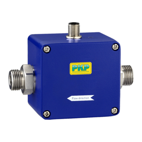
PKP DTL06 User manual

Instruction Manual
DTL06
Calorimetric flow sensor for air
-analogue output-
PKP Prozessmesstechnik GmbH
Borsigstraße 24
D-65205 Wiesbaden- ordenstadt
Tel.: ++49-(0)6122-7055-0
Fax: ++49-(0)6122-7055-50
Email: info@pkp.de - www.pkp.de

Table of Contents
Safety Information..................................................................................................................2
Functional Description...........................................................................................................3
Installation instruction............................................................................................................3
Electrical Connection.............................................................................................................4
Commissioning.......................................................................................................................4
Maintenance and Cleaning....................................................................................................5
Troubleshooting.....................................................................................................................5
Safety Information
General Instructions
To ensure safe operation, the device should only be operated according to the specifica-
tions in the instruction manual. The requisite Health & Safety regulations for a given appli-
cation must also be observed. This statement also applies to the use of accessories.
Every person who is commissioned with the initiation or operation of this device must have
read and understood the operating instructions and in particular the safety instructions!
The liability of the manufacturer expires in the event of damage due to improper use, non-
observance of this operating manual, use of insufficiently qualified personnel and unau-
thorized modification of the device.
Proper sage
The calorimetric compact flowmeters type DTL06 are used for measuring air flows. Any
other use of the device is prohibited and outside the scope of application.
In particular, applications in which shock loads occur (for example, pulsed operation)
should be discussed and checked in advance with our technical staff.
The series DTL06 flow meter devices should not be deployed as the sole agents to pre-
vent dangerous conditions occurring in plant or machinery. Machinery and plant need to
be designed in such a manner that faulty conditions and malfunctions do not arise that
could pose a safety risk for operators.
Dangerous substances
For dangerous media such as e.g. Oxygen, Acetylene, flammable or toxic substances as
well as refrigeration systems, compressors, etc. must comply with the relevant regulations
beyond the general rules.
DTL06 Instruction manual 05/2021 page 2

Qualified Personnel
The DTL06 devices may only be installed by trained, qualified personnel who are able to
mount the devices correctly. Qualified personnel are persons, who are familiar with
assembling, installation, placing in service and operating these devices and who are suit-
ably trained and qualified.
Inward Monitoring
Please check directly after delivery the device for any transport damages and deficiencies.
Additional with reference to the accompanying delivery note the number of parts must be
checked.
Claims for replacement or goods which relate to transport damage can only be considered
valid if the delivery company is notified without delay.
Functional Description
A temperature-sensitive resistor is heated according to the calorimetric measuring
principle. The temperature-sensitive resistor is heated by a second resistor. A flow in the
medium dissipates heat from the measuring resistor, causing the resistor temperature an
impedance to change. This temperature change is evaluated. Since both the velocity and
the temperature of the flowing medium affect the dissipated heat, a relationship must be
created between flow and temperature. For this purpose, a second temperature-
dependent measuring resistor is located next to the first one. The second measuring
resistor (temperature compensation) is not heated and is only used for the temperature
measurement.
Installation instruction
In order to avoid malfunctions, the following points must be observed:
•The sensor should be mounted in such a way that the air flow passes through the
lateral opening. The marking is intended as an assembly aid.
•Installation where there is low turbulence, if possible.
•Do not install directly behind bends (distance approx 10x bend radius).
•Install the probe in the middle of the duct where possible (distance at least 1/3 of
the duct diameter from the wall).
•Do not install directly behind the heating register (rapid changes in temperature
may lead to the measured values being falsified.
DTL06 Instruction manual 05/2021 page 3

Electrical Connection
Attention: Before the electrical connection of the device, it must be ensured that the sup-
ply voltage corresponds to the required one and that the supply voltage is switched off.
Connection to mains supply (L, ) must be made by means of a protected isolating switch
with the usual fuses. As a matter of principle, the General VDE Regulations must be
complied with (VDE 0100, VDE 0113, VDE 0160).
Wiring diagram:
Commissioning
Commissioning the DTL06 you need to follow these points:
1. install the device (see also: “Installation instruction”!)
2. connect the device regarding to the manual
3. set potentiometer “sensitivity” to minimum sensitivity
4. switch on supply voltage; The device is instantly operational.
5. switch on the working flow
6. turn potentiometer “sensitivity” to the needed output voltage
(e.g. flow=5 m/s -> U=5 V)
7. to check for proper operation, please lower or switch off the flow. The yellow LED
should darken and the transistor output disconnects.
DTL06 Instruction manual 05/2021 page 4

Maintenance and Cleaning
The calorimetric flow monitors described here are basically maintenance-free. They do not
contain any components that have to be repaired or replaced on site. Repairs are only
carried out at the manufacturer´s works.
The airflow sensor contains a sensor element which is sensitivity to mechanical loading
and which must not be touched with hard and pointed objects. Any cleaning that may be
necessary is possible in water (also with addition of detergents). Let the unit drip off and
dry renewed start-up.
Troubleshooting
Problem Cause Solution
Device does not work at all o or wrong mains voltage
connected
Check mains voltage and con-
nection
Device does not detect flow Sensor is not installed correctly
Sensor is highly plluted
Check installation conditions
Clean the sensor
Device shows unusual
response
Sensor is heavily contaminated
by the medium
Clean the sensor
Mistakes and misprints are not to be excluded. All information „without guarantee“.
DTL06 Instruction manual 05/2021 page 5

Flow Measurement and Monitoring
DTL06
Calorimetric Flow Sensor
for Air
-Analogue Output-
•analogue output 0... 0 V
•measuring range: 0, ...30 m/s
•max. pressure: 0 bar
•max. temperature: 70 °C
•negligible pressure loss
•no moving parts
•independent of nominal diameter, pressure
and temperature
Description:
The air flow meters work according to the proven aclorimetric
principle. A temperature-independent resistance at the sensor
tip is electronically heated. The flowing air withdraws heat
from it, which changes the resistance value. A second
unheated resistor is used to measure the medium
temperature.
The temperature difference between the two resistances is
proportional to the flow velocity and thus to the volume flow.
The measured values of the DTL0 can be read off
analogously by a voltage signal, which is simply set on site via
a built-in potentiometer.
Typical applications:
The DTL0 calorimetric flowmeters are characterized by their
particularly good price-perfomance ratio. The devices are
used wherever laminar air flows have to be measured or
monitored: For example in building services engineering, air
supply, compressor monitoring, consumption measurement,
leakage monitoring, cooling circuits, etc.
PKP Prozessmesstechnik GmbH
Borsigstr. 24 • D- 5205 Wiesbaden
S +49 (0) 122-7055-0 • T +49 (0) 122 7055-50
[email protected] • www.pkp.de
20190731

Models:
DTL06.A... Linear analogue output for flow
Technical Data:
Meas ring range: 0…30 m/s
Analog e o tp t: 0...10 V, (Ra = 10 kOhm)
adjustable via potentiometer
Acc racy of the o tp t
signal: +/- 10 % of measured value
Reprod cibility of the
o tp t signal: +/- 2 % of FS
Operating voltage: 24 VAC/DC, +/- 5%
Signal display
operating voltage: green LED
Power cons mption max. 2 VA
Temperat re range:
ambient
medi m
−20 … + 0 °C
0 … +70 °C
Temperat re gradient: 15 K/min
Compression strength: 10 bar
Process connection: PG 7
mounting flange
G ½ reduction
Immersion depth: 130 mm
Sensor material: brass 58 nickel plated
Connection: 3 clamps, 2,5 mm²
Protection class ho sing: IP54
Protection class sensor: IP 7
* Reference conditions: 20 °C, 48 % r.h., 101 mbar
Electrical Connection:
Order Code:
Order n mber: DTL06.
Calorimetric flow sensor for air
-analog e o tp t-
A. 30. 1. 0
Model:
A = analogue output 0...10 V
Meas ring range:
30 = 0,1…30 m/s
Process connection:
1 = PG7 thread
2 = mounting flange
3 = G ½ reduction
Options:
0 = without
9 = please specify in plain text
Dimensions:
PKP Prozessmesstechnik GmbH
Borsigstr. 24 • D- 5205 Wiesbaden
S +49 (0) 122-7055-0 • T +49 (0) 122 7055-50
[email protected] • www.pkp.de
Flow
Table of contents
Other PKP Measuring Instrument manuals
Popular Measuring Instrument manuals by other brands

Liverage
Liverage Fiber Checker User manual and specifications

TRIDON
TRIDON TOLEDO Vernier Caliper user guide

PCE Instruments
PCE Instruments PCE-2800 manual

Argus
Argus PiCUS Tree Motion Sensor Online Hardware manual

AR
AR DC3010A Operating and service manual

Sekonic
Sekonic LITEMASTER PRO L-478DR-A-EL Startup guide