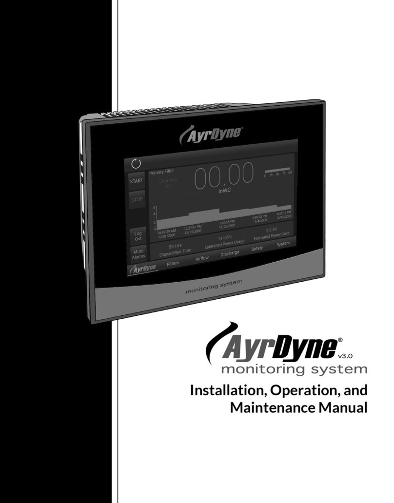
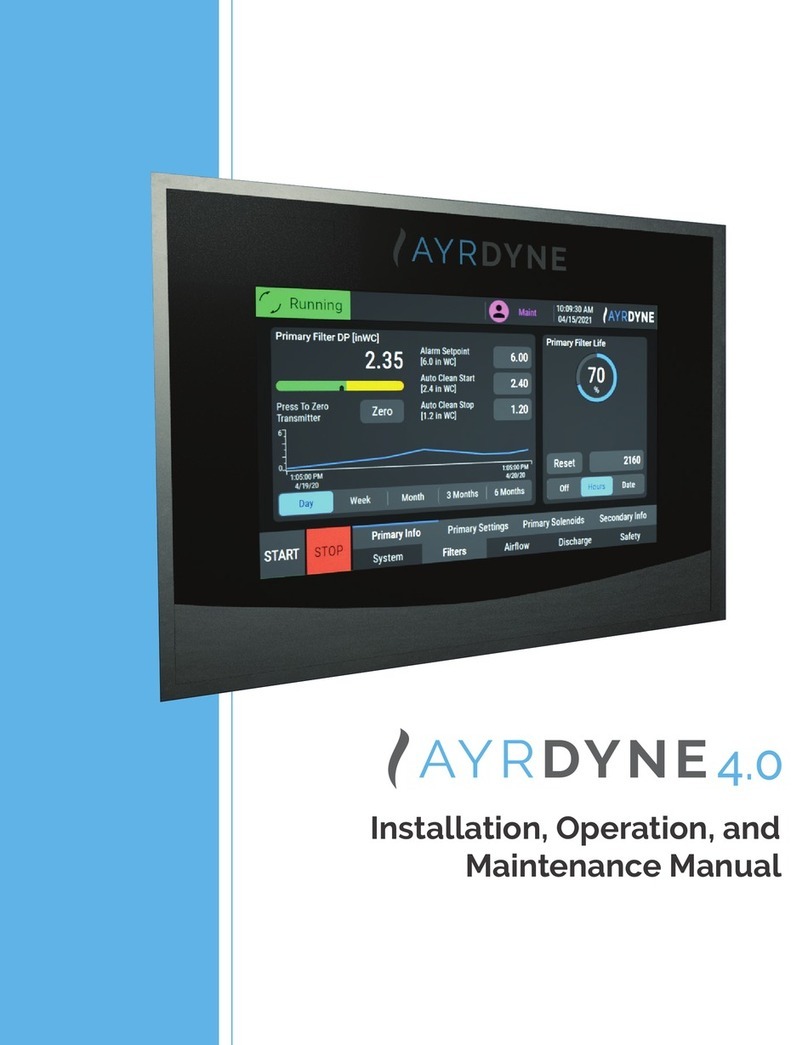
Dentech AYRDYNE User manual

www.ayrdyne.com
Installation, Operation, and
Maintenance Manual

www.ayrdyne.comwww.ayrdyne.com
1.1 Introduction
1.2 Safety
2.1 Removal of HMI
2.2 Installation of HMI
2.3 Removal of PLC
3.1 System
3.2 Filters
3.3 Airow
3.4 Discharge
3.5 Safety
4.1 Alarms
5.1 Glossary
2.3.1 Installing and Removing
the CPU from the DIN rail
3.1.1 Status Bar
3.1.2 Navigation Bar
3.1.3 Main Screen
3.2.1 Primary Information
3.2.2 Primary Settings
3.2.3 Primary Solenoids
3.2.4 Secondary Information
3.3.1 Static Pressure
3.3.2 Velocity
3.3.3 VFD Settings
3.3.4 Blower Maintenance
3.4.1 Rotary Valve
3.4.2 Double Dump Valve
3.5.1 Safety Circuit & Isolation Valve
2.3.2 Installing and Removing
an SB, CB or BB
2.3.3 Installing or Replacing the Battery
in the BB 1297 battery board
2.3.4 Installing and Removing an SM
2.3.5 Installing and Removing
an CM or CP
2.3.6 Removing and Reinstalling the
S7-1200 Terminal block
connector
TABLE OF CONTENTS
1
1 OVERVIEW
2 INSTALLATION
& REMOVAL
3 OPERATION
4 TROUBLESHOOTING
5 GLOSSARY
. . . . . . . . . . . . . . . . 2
. . . . . . . . . . . . . . . . . . . 3
. . . . . . . . . . . . . . 4
. . . . . . . . . . . . . 6
. . . . . . . . . . . . . . 8
. . . . 8
. . . . . . . . . 9
. . 10
10
. . . . . . . . . . 12
. . . . . . . . . . . 13
. . . . . . . . . . . . . . . . . . 15
. . . . . . . . . . . 16
. . . . . . . . . 17
. . . . . . . . . . 18
. . . . . . . . . . . . . . . . . . . 28
. . . . . . . . . . . . . . . . . . 34
. . . . . . . . . . . . . . . . . . . 42
. . . . . . . . . . . . . . . . . . 46
. . . . . . . . . . . . . . . . . . 48
. . . . . . . . . . . . . . . . . 50
. . . . . . 28
. . . . . . . . 30
. . . . . . . 32
. . . . . 33
. . . . . . . . . 34
. . . . . . . . . . . . . 36
. . . . . . . . . . 38
. . . . . . 40
. . . . . . . . . . 42
. . . . . . . 44
46

www.ayrdyne.comwww.ayrdyne.com
SAFETYINTRODUCTION
OVERVIEW
SAFETY
2
OVERVIEW
3
The installation, maintenance, operation, and
care of the AyrDyne® Monitoring System Human
Machine Interface (HMI) should only be performed
by individuals who are qualied and trained
to do so. A “qualied” person in this context is a
person who has skills and knowledge related to the
construction and operation of electrical equipment
and its installation through both work experience
and training. Additionally, a qualied person is one
who has received and undergone safety training
specic to electrical maintenance. Anyone who has
not undergone safety training specic to this system
should not operate or perform maintenance on the
system.
In terms of maintenance of this system, “lock out tag
out” safety protocol applies. This means that any
time maintenance on this system is performed, the
machine must be shut down, unplugged and tagged
or labeled, explaining that maintenance is taking
place.
DenTech is not liable for any
consequences arising from misuse of
this system. If you are unsure of whether you
are qualied to use or maintain this system, please
contact an electrician or other qualied professional
for assistance. Failure to follow safety protocol for
this and any other system could result in serious
bodily harm or other injury. No responsibility is
assumed by DenTech for any consequences arising
out of the use of this material.
1.1
The purpose of this document is to outline
proper installation, maintenance, operation,
and care of the AyrDyne® Monitoring
System Human Machine Interface (HMI). This
document is in no way intended to be used
to determine the reliability of this product
outside of its originally intended application.
It is the duty of the end user or integrator to
perform the appropriate risk analysis in order
to determine the relevance of its use within any
specic application.
All pertinent state, regional, and local
safety regulations must be observed when
installing and using this product. For reasons
of safety and to help ensure compliance
with documented system data, only the
manufacturer should perform repairs to
components.
Failure to follow the guidelines outlined in
this manual may result in injury, harm, or
improper operating results. Failure to observe
this information may also result in equipment
damage, premature wear, or failure.
This symbol indicates that an electrical hazard
exists which could result in personal injury if
the instructions are not followed.
This safety alert symbol is used to alert you
to potential personal injury hazards. Obey all
safety messages that follow this symbol to
avoid possible injury or death.

www.ayrdyne.comwww.ayrdyne.com
1
2.1 REMOVAL OF HMI
REMOVAL OF HMIREMOVAL OF HMI
INSTALLATION & REMOVAL
4
INSTALLATION & REMOVAL
5
Figure 2.1.1a
Figure 2.1.1b
Front view of HMI.
Rear view of HMI.
Figure 2.1.1c
Figure 2.1.2
Power connection removed from HMI.
Ground wire with T-20 Torx screw.
Pull green connector downward to remove
power connection from HMI.
Use a T-20 Torx screwdriver to remove the
ground wire.
2.1 2.1
2
MECHANICALLY UNSTABLE TERMINAL
Always keep HMI stable in panel cut-out while you
are installing or removing installation fasteners.
FAILURE TO FOLLOW THESE INSTRUCTIONS MAY
RESULT IN INJURY, OR EQUIPMENT DAMAGE.
CAUTION!
ELECTRICAL SHOCK HAZARD EXISTS
- Ensure that the control enclosure within
which you are working is powered down
and locked out.
- Verify that all power sources are in a zero
energy state.
FAILURE TO FOLLOW THESE INSTRUCTIONS MAY
RESULT IN INJURY, DEATH, OR EQUIPMENT DAMAGE.
WARNING!

www.ayrdyne.comwww.ayrdyne.com
REMOVAL & INSTALLATIONREMOVAL
INSTALLATION & REMOVAL
6
INSTALLATION & REMOVAL
7
Figure 2.1.3
Figure 2.1.4
Loosening HMI fasteners.
Installation fasteners removed.
Figure 2.1.5a
Figure 2.1.5b
Removal of the HMI from the front of the enclosure.
HMI completely removed.
With the HMI free from all electrical wiring,
begin to loosen the 10 installation fasteners
that secure the HMI to the control enclosure
door using a small at head screwdriver. Make
sure to support the HMI with the other hand.
Continue to loosen fasteners until they can be
removed from the HMI.
Once the installation fasteners have been
removed, gently remove the AyrDyne
HMI from the front of the enclosure door,
taking care not to damage or displace the
installation gasket.
2.1 2.1
3
4
5
To install the HMI, follow the steps on pages
six through nine in reverse order.
1
2.2 INSTALLATION OF HMI

www.ayrdyne.comwww.ayrdyne.com
INSTALLING & REMOVING PLCINSTALLING & REMOVING PLC
8 9
For the removal of the PLC portion of the AyrDyne
Monitoring System, please visit the AyrDyne website
for a link to the Siemens installation manual.
Siemens S7-1200 Manual System Manual, 04/2012,
A5E02486680-06
Pages 50-55
// A) REMOVING AN SB, CB, OR BB
2.3 2.3
2.3.2 INSTALLING & REMOVING AN SB, CB OR BB
TASK PROCEDURE
1. Ensure that the CPU and all S7-1200 equipment are
disconnected from electrical power.
2. Disconnect the I/O connectors, wiring, and cables from the
CPU (Page 55).
3. Remove the CPU and any attached communication
modules as a unit. All signal modules should remain
installed.
4. If an SM is connected to the CPU, retract the bus
connector:
– Place a screwdriver beside the tab on the top of the
signal module.
– Press down to disengage the connector from the CPU.
– Slide the tab fully to the right.
5. Remove the CPU:
– Pull out the DIN rail clip to release the CPU from the
rail.
– Rotate the CPU up and o the rail, and remove the
CPU from the system.
TASK PROCEDURE
1. Ensure that the CPU and all S7-1200 equipment
are disconnected from electrical power.
2. Remove the top and bottom terminal block
covers from the CPU.
3. Place a screwdriver into the slot on top of the
CPU at the rear of the cover.
4. Gently pry the cover up and remove it from the
CPU.
5. Place the module straight down into its mounting
position in the top of the CPU.
6. Firmly press the module into position until it
snaps into place.
7. Replace the terminal block covers.
TASK PROCEDURE
1. Ensure that the CPU and all S7-1200 equipment
are disconnected from electrical power.
2. Remove the top and bottom terminal block
covers from the CPU.
3. Place a screwdriver into the slot on top of the
module.
4. Gently pry the module up to disengage it from
the CPU.
5. Remove the module straight up from its
mounting position in the top of the CPU.
6. Replace the cover onto the CPU.
7. Replace the terminal block covers.
TASK PROCEDURE
1. Install the DIN rail. Secure the rail to the mounting panel every 75 mm.
2. Ensure that the CPU and all S7-1200 equipment are disconnected from
electrical power.
3. Hook the CPU over the top of the DIN rail.
4. Pull out the DIN rail clip on the bottom of the CPU to allow the CPU to t over
the rail.
5. Rotate the CPU down into position on the rail.
6. Push in the clips to latch the CPU to the rail.
// B) REMOVING THE CPU FROM A DIN RAIL
// A) INSTALLING THE CPU ON A DIN RAIL
// A) INSTALLING AN SB, CB, OR BB
INSTALLATION & REMOVAL INSTALLATION & REMOVAL
2.3.1 INSTALLING & REMOVING THE CPU ON A DIN RAIL

www.ayrdyne.comwww.ayrdyne.com
INSTALLING & REMOVING PLCINSTALLING & REMOVING PLC
10 11
// A) INSTALLING AN SM
2.3.3 INSTALLING OR REPLACING THE BATTERY IN BB 1297 BATTERY BOARD
2.3.4 INSTALLING & REMOVING AN SM
2.3 2.3
TASK PROCEDURE
Install your SM after installing the CPU.
1. Ensure that the CPU and all S7-1200 equipment are disconnected
from electrical power.
2. Remove the cover for the connector from the right side of the CPU.
3. Insert a screwdriver into the slot above the cover.
4. Gently pry the cover out at its top and remove the cover. Retain the
cover for reuse.
Connect the SM to the CPU:
1. Position the SM beside the CPU.
2. Hook the SM over the top of the DIN rail.
3. Pull out the bottom DIN rail clip to allow the SM to t over the rail.
4. Rotate the SM down into position beside the CPU and push the
bottom clip in to latch the SM onto the rail.
Extending the bus connector makes both mechanical and electrical connections for the SM.
1. Place a screwdriver beside the tab on the top of the SM.
2. Slide the tab fully to the left to extend the bus connector into the CPU. Follow the same
procedure to install a signal module to a signal module.
TASK PROCEDURE
You can remove any SM without removing the CPU or other SMs in place.
1. Ensure that the CPU and all S7-1200 equipment are disconnected from
electrical power.
2. Remove the I/O connectors and wiring from the SM (Page 55).
3. Retract the bus connector.
– Place a screwdriver beside the tab on the top of the SM.
– Press down to disengage the connector from the CPU.
– Slide the tab fully to the right.
If there is another SM to the right, repeat this procedure for that SM.
Remove the SM:
1. Pull out the bottom DIN rail clip to release the SM from the rail.
2. Rotate the SM up and o the rail. Remove the SM from the system.
3. If required, cover the bus connector on the CPU to avoid contamination.
Follow the same procedure to remove a signal module from a signal module.
// B) REMOVING AN SM
INSTALLATION & REMOVAL INSTALLATION & REMOVAL
The BB 1297 requires battery type CR1025. The battery
is not included with the BB 1297 and must be purchased
by the user.
TO INSTALL A NEW BATTERY,
FOLLOW THESE STEPS:
TO REPLACE THE BATTERY IN THE BB 1297:
In the BB 1297, install a new battery with
the positive side of the battery on top, and
the negative side next to the printed wiring
board.
The BB 1297 is ready to be installed in the
CPU. Follow the installation directions on
page 11 to install the BB 1297.
1
2
Remove the BB 1297 from the CPU following
the removal directions on page 11.
Carefully remove the old battery using a
small screwdriver. Push the battery out from
under the clip.
Install a new CR1025 replacement battery
with the positive side of the battery on top
and the negative side next to the printed
wiring board.
Re-install the BB 1297 battery board following
the installation directions on page 11.
1
2
3
4

www.ayrdyne.comwww.ayrdyne.com
INSTALLING & REMOVING PLCINSTALLING & REMOVING PLC
// A) REMOVING THE CONNECTOR
// B) REMOVING A CM OR CP
// A) INSTALLING A CM OR CP
12 13
Attach any communication modules to the CPU and install the assembly as a unit, as shown in Installing
and Removing the CPU (page 49). The CPU, SB, and SM modules provide removable connectors to make connecting the wiring easy.
2.3 2.3
2.3.5 INSTALLING & REMOVING A CM OR CP 2.3.6 REMOVING & REINSTALLING THE S7-1200 TERMINAL BLOCK CONNECTOR
TASK PROCEDURE
1. Ensure that the CPU and all S7-1200 equipment are
disconnected from electrical power.
2. Attach the CM to the CPU before installing the assembly as a
unit to the DIN rail or panel.
3. Remove the bus cover from the left side of the CPU:
– Insert a screwdriver into the slot above the bus cover.
– Gently pry out the cover at its top.
4. Remove the bus cover. Retain the cover for reuse.
5. Connect the CM or CP to the CPU:
– Align the bus connector and the posts of the CM with the
holes of the CPU
– Firmly press the units together until the posts snap into
place.
6. Install the CPU and CP on a DIN rail or panel.
TASK PROCEDURE
Remove the CPU and CM as a unit from the DIN rail or panel.
1. Ensure that the CPU and all S7-1200 equipment are disconnected from
electrical power.
2. Remove the I/O connectors and all wiring and cables from the CPU and CMs.
3. For DIN rail mounting, move the lower DIN rail clips on the CPU and CMs to
the extended position.
4. Remove the CPU and CMs from the DIN rail or panel.
5. Grasp the CPU and CMs rmly and pull apart.
TASK PROCEDURE
Prepare the system for terminal block connector removal by removing the power
from the CPU and opening the cover above the connector.
1. Ensure that the CPU and all S7-1200 equipment are disconnected from
electrical power.
2. Inspect the top of the connector and locate the slot for the tip of the
screwdriver.
3. Insert a screwdriver into the slot.
4. Gently pry the top of the connector away from the CPU. The connector will
release with a snap.
5. Grasp the connector and remove it from the CPU.
// B) INSTALLING THE CONNECTOR
TASK PROCEDURE
Prepare the components for terminal block installation by removing power from
the CPU and opening the cover for connector.
1. Ensure that the CPU and all S7-1200 equipment are disconnected from
electrical power.
2. Align the connector with the pins on the unit.
3. Align the wiring edge of the connector inside the rim of the connector base.
4. Press rmly down and rotate the connector until it snaps into place.
Check carefully to ensure that the connector is properly aligned and fully
engaged.
INSTALLATION & REMOVAL INSTALLATION & REMOVAL
CAUTION!
Do not use a tool to separate the modules because this will
damage the units.

www.ayrdyne.comwww.ayrdyne.com
SYSTEM
OPERATION
14
This section convers the navigation and operation of the standard AyrDyne monitoring system. The
operation and functionality of each screen is covered in detail in later sections. The table below shows the
layout of the screens. Available screens depend on system requirements and conguration.
Airow
Safety
System
Filters
Discharge
Alarms
Settings
Overview
Primary Info
Airow Control
Primary Solenoids
Metrics
Primary Settings
VFD Settings
Secondary Info
Maintenance
Alarms monitoring and control
Contains all monitoring, settings, and controls related to airow
Contains all monitoring, settings, and controls related to safety
An overview of the system and the rst screen to display
when power is applied
Primary lter dierential pressure monitoring and cleaning
Airow monitoring and control settings
Primary lter cleaning system monitoring and manual
control
Contains system wide monitoring, settings, and controls
Contains all monitoring, settings, and controls related to the lters
Contains all monitoring, settings, and controls related to the discharge system
System Metrics
Primary lter cleaning settings
Airow monitoring and control settings
Secondary lter dierential pressure monitoring
Motor maintenance
OPERATION
15
3.1.0 OPERATION OVERVIEWNOTES
3.1 3.1

www.ayrdyne.comwww.ayrdyne.com
SYSTEMSYSTEM
16 17
3.1.1 STATUS BAR OVERVIEW 3.1.2 NAVIGATION BAR OVERVIEW
The status bar, which displays system information, is visible in all screens. This bar displays system
information, active alarm description and corrective action. The navigation bar is located at the bottom of each screen and can be used to navigate through the
various systems. The underline indicates the section currently displayed. The circle with the exclamation
symbol denotes when a section is in alarm.
USER
Shows the user that is currently logged in.
Pressing the user icon will logout the current
user.
TIME AND DATE
This graphic display shows the internal date
and time. Pressing the time and will display a
pop-up entry page where the date and time
can be adjusted.
LOGO
This graphic display shows the logo
of the company that you may contact
for information on the system, spare or
replacement parts ordering and help with
the system. Pressing the logo will display the
contact information. Once on the information
screen, you may press anywhere on the
screen to return to the home screen.
4
5
3
START
This button starts the system.
STOP
This button stops the system on the rst
press and stops the downtime cleaning, if
running, on the second press.
SYSTEM
This button displays the system screen
FILTERS
This button displays the lters screen
1
2
2
3
3
4
4
AIRFLOW
This button displays the airow screen
DISCHARGE
This button displays the discharge screen
SAFETY
This button displays the safety screen
5
5
6
6
7
7
SYSTEM STATE INDICATOR
This graphic display shows the current
system state.
SYSTEM FAULTS
This text display shows details of any active
faults as well as corrective actions.
1
2
System is Stopped
System is Running
System is Cleaning
System is Faulted
3.13.1
OPERATION OPERATION
14 5321

www.ayrdyne.comwww.ayrdyne.com
SYSTEMSYSTEM
18
3.1.3 MAIN SCREEN OVERVIEW
19
PRIMARY FILTER DP
This numeric display and dial display show
the lter dierential pressure measured
between the dirty and clean sides of the
lters.
PRIMARY FILTER LIFE
This numeric display and dial display show
lter status and remaining life.
DATA PLOT
This graphical display shows the lter
dierential pressure over time. The time line
view can be changed from one day to 6
months.
AIRFLOW
This numeric display and bar graph show the
system static pressure, velocity or volume
measured between the clean side of the lter
and atmosphere.
VFD (Hertz)
This numeric display shows VFD output
frequency.
UPTIME (Hrs)
This numeric display shows the total time
that the collector has been powered on.
AUTO STOP (Hrs)
This shows the status of the auto stop
Auto Stop Disabled by REM run:
Auto stop is not available when
using the remote run signal
Schedule Auto Stop:
Press and follow onscreen prompts
to schedule an auto stop
Auto Stop in hhh:mm:ss:
Shows the remaining hours, minutes
and seconds until the system
automatically stops
1
2
3
4
5
6
7
9
8
3.1 3.1
a
b
c
RUNNING TIME (%)
This numeric display shows what percentage
of the up time was spent running.
STOPPED TIME (%)
This numeric display shows what percentage
of the up time was spent stopped.
FAULTED TIME (%)
This numeric display shows what percentage
of the up time was spent in a fault condition.
10
OPERATION OPERATION
9
8
7
10
1
3
2 4 5
6

www.ayrdyne.comwww.ayrdyne.com
SYSTEMSYSTEM
20
3.1.4 METRICS (STATIC PRESSURE)
21
1
2
5
6
3
4
7
9
8
10
11
12
13
14
RUNTIME (h)
This numeric display shows the total system
runtime for the calendar year. This metric is
not resettable.
SP AVE (in WC)
This numeric display shows the average
Static Pressure for the calendar year. This
metric is not resettable.
HZ AVE (Hz)
This numeric display shows the average
blower frequency for the calendar year. This
metric is not resettable.
DP
This numeric display shows the average
Dierential Pressure for the calendar year.
This metric is not resettable.
CLEAN PULSES
This numeric display shows total cleaning
pulses executed by the bag cleaning
system for the calendar year if equipped.
MONTH
This column shows the month of year for
the saved metrics. Blue numbers in the
corresponding rows represent the current
month.
RUN (H)
This numeric display shows the total system
runtime for the corresponding month. This
metric is not resettable.
SP (in WC) / FPM
This numeric display shows the average
Static Pressure or FPM, depending on
system conguration, for the corresponding
month. This metric is not resettable.
HZ (Hz)
This numeric display shows the average
blower frequency for the corresponding
month. This metric is not resettable.
DP
This numeric display shows the average
Dierential Pressure for the corresponding
month. This metric is not resettable.
PULSES
This numeric display shows the total
number of cleaning pulses for the
corresponding month. This metric is not
resettable.
POWER SAVINGS TOTAL (USD)
This numeric display, visible when equipped
with a VFD, shows estimated power usage
cost saved in comparison to a motor starter.
POWER SAVINGS YEAR-TO-DATE (USD)
This numeric display, visible when equipped
with a VFD, shows estimated power usage
cost saved on a yearly basis in comparison
to a motor starter.
ESTIMATED POWER USAGE MONTH
DISPLAY
This bar graph shows estimated power
usage each month if equipped with a VFD.
3.1 3.1
OPERATION OPERATION
1
2
3
4
5
6
14
7 8 9 10 11
13
12

www.ayrdyne.comwww.ayrdyne.com
SYSTEMSYSTEM
22 23
ACTIVE
This tab shows currently active faults with a
time stamp of when the fault occurred and
description of that alarm.
1HISTORY
This tab shows previously active faults with
a time stamp and description of the fault.
RELOAD
This button reloads the alarm history on the
screen.
DELETE
This button deletes the alarm history on the
screen.
2
3
4
3.1 3.1
3.1.5 ALARMS
OPERATION OPERATION
1
2
3
4

www.ayrdyne.comwww.ayrdyne.com
SYSTEMSYSTEM
AUTO LOGON
Allows the manager to setup Auto Logon.
When enabled, the system will attempt
to log on the user as specied in the user
and password elds. Note that these elds
are NOT linked to the user administration
table and thus changing user names and
passwords in the table, will break the auto
logon feature until the user and password
are updated in the auto logon elds.
DEFAULT USERS AND PASSWORDS
The system ships with the default users and
passwords below. Make sure to make your
passwords secure and document them.
User: maint Password: 123
User: manager Password: 123
User: operator Password: 123
24
3.1.6 SETTINGS - USERS
25
1 2
3
USER ADMINISTRATION TABLE
This table allows administration of users.
See the list of dierent
User:
Shows the users in the system. To
add a user, login as a manager and
click on empty row and assign a
user, password, group and logo
time.
Password:
Shows the password for the
respective user. To change, click
on password and follow on-screen
prompts.
Group:
Shows the group for the respective
user.
Manager: Can perform any
operation on the system as
well as add / remove users,
change group assignments
and passwords for any user.
Maintenance: Can
perform any operation
except for user
administration. May change
its own password or logo
time.
Operator: Can change
settings on the system that
are not part of the airow
and balancing. May change
its own password or logo
time.
Logotime:
Shows the inactivity time in minutes
that the respective user would have
prior to being logged o
automatically.
3.1 3.1
a
a
b
c
b
c
d
OPERATION OPERATION
i.
ii.
iii.
1a
2 3
ci
cii
ciii
1b 1c 1d

www.ayrdyne.comwww.ayrdyne.com
SYSTEMSYSTEM
26
3.1.7 SETTINGS - I/O
27
1
2
3
DIGITAL IN
This graphic display shows the status of
each input. A gray number indicates that
the corresponding input is OFF; a yellow
number indicates that the corresponding
input is ON. Each input may also be ipped
by the “Flip” button immediately to the right.
When the “Flip” button is gray, the input
remains as wired; when the “Flip” button is
blue, the input state is ipped. The number
immediately to the right of the “Flip” button
shows the status of the input as evaluated in
the program.
DIGITAL OUT
This graphic display shows the status of
each output. A gray number indicates that
the corresponding output is OFF; a yellow
number indicates that the corresponding
output is ON.
ANALOG IN / OUT
This graphic display shows the signal of
each analog input / output from 0 – 100%.
3.1 3.1
OPERATION OPERATION
1 32

www.ayrdyne.comwww.ayrdyne.com
FILTERSFILTERS
28
3.2.1 PRIMARY INFO
29
PRIMARY FILTER DP
This numeric display and bar-graph show the
lter dierential pressure measured between
the dirty and clean sides of the lters.
ZERO METER
The Zero push button will zero the dierential
pressure reading, should it wander from
zero over the lifespan of the dierential
pressure sensor. This can only be done when
the system is not running. Additionally, the
pneumatic tubing should be disconnected
from the control panel.
ALARM SET POINT
This numeric entry/display shows the set
point that the dierential pressure must
rise above to initiate an alarm. This value is
adjustable between the Clean Start Set Point
and max transmitter output. Recommended
setting is 6 inWC.
AUTO CLEAN START
This numeric entry/display shows the set
point that the dierential pressure must
rise above to start On Demand cleaning.
This value is adjustable between the
Clean Stop Set Point and Alarm Set point.
Recommended setting is 2.4 inWC.
CLEAN STOP SET POINT
This numeric entry/display shows the set
point that the dierential pressure must fall
below to stop On Demand cleaning. This
value is adjustable between min transmitter
output and the Clean Start Set Point.
Recommended setting is 1.2 inWC
DATA PLOT
This graphical display shows the lter
dierential pressure over time. The time line
view can be changed from one day to 3
months.
PRIMARY FILTER LIFE
The lter life shows the remaining life of the
lter. When the lter is nearing end of life, it
will remind you to order or schedule the lter
change. Once the lter has reached end of
life, it will prompt you to change the lter.
RESET
This button resets the hour meter or date,
after the lters have been replaced.
1 7
8
2
3
4
5
6
3.2 3.2
OPERATION OPERATION
6
1 7
8
2
3
4

www.ayrdyne.comwww.ayrdyne.com
FILTERSFILTERS
30
3.2.2 PRIMARY SETTINGS
31
MODE
These toggles select the mode of cleaning
OFF
This toggle switch turns the cleaning system
o.
AUTO
This toggle switch turns the cleaning
system to automatic mode. In this mode, the
cleaning sequence is activated anytime the
dierential pressure reaches Auto Clean Start
setpoint and stops when it reaches the Auto
Clean Stop setpoint.
HAND
This toggle switch turns the cleaning system
on to clean constantly.
DOWNTIME DELAY (s)
This numeric entry/display shows how long
after the collector is shut down that the
downtime cleaning will start in seconds.
PULSES PER SOLENOID
This numeric entry/display shows how many
times each solenoid should be pulsed during
downtime cleaning.
COMPRESSED AIR SAVER
This toggle turns the Compressed Air saver
on and o. When enabled, the Auto Clean
Start and Auto Clean Stop setpoints will be
increased if the Auto Clean is active for 8
consecutive hours.
DOWNTIME BLOWER SPEED (Hz)
This numeric entry/display shows how long
after the collector is shut down that the
downtime cleaning will start in seconds.
PULSE DURATION (ms)
This numeric entry/display shows the
duration of each cleaning pulse. This value is
adjustable between 50 and 500 milliseconds.
Recommended setting is 100 ms.
PULSE SPACING (s)
This numeric entry/display shows the delay
between each cleaning pulse. The elapsed
time display (xx /) shows how long until the
next pulse. This value is adjustable between
1 and 20 seconds. Recommended setting is
10 s.
SECONDARY PULSE
This toggle switch turns on pulsing of
alternating manifolds to reduce downtime
cleaning time without aecting air recovery.
1
2
3
4
5
6
7
8
9
3.2 3.2
10
11
OPERATION OPERATION
1 9
10
11
2 3 4 5
7 8
6

www.ayrdyne.comwww.ayrdyne.com
FILTERSFILTERS
32
3.2.3 PRIMARY SOLENOIDS 3.2.4 SECONDARY INFORMATION
33
COMPRESSED AIR MONITORING
When equipped with a Compressed Air
Monitoring Device, the solenoids will appear
with an orange highlight, if a fault is detected.
The number of modules and valves per
module is dependent upon the user’s
system. Modules not displayed on the screen
may be selected from the navigation buttons
on the left of the screen.
1
3.2 3.2
This screen enables the user to manually pulse each solenoid valve on the selected Module. Each
solenoid is numbered and may be pressed to manually re the solenoid valve.
The Compressed Air Monitoring Device
detects solenoid failures and leaks, if
equipped with the airow monitoring
device. When the same solenoid fails to
pulse three times, it is highlighted orange
and an alarm produced. In addition, the
monitoring system will also detect air leaks
on the solenoid manifold, at which time it
will alarm. The leak can also be pointed to a
solenoid if it started after a specic solenoid
was pulsed.
OPERATION OPERATION
1
1
6
53
DATA PLOT
This graphical display shows the lter
dierential pressure over time. The time line
view can be changed from one day to 6
months.
SECONDARY FILTER LIFE
The lter life shows the remaining life of the
lter. When the lter is nearing end of life, it
will remind you to order or schedule the lter
change. Once the lter has reached end of
life, it will prompt you to change the lter.
RESET
This button resets the hour meter or date,
after the lters have been replaced.
SECONDARY FILTER DP
This numeric display and bar-graph show
the lter dierential pressure measured
between the dirty and clean sides of the
lters.
ZERO METER
The Zero push button will zero any
dierential pressure reading, should it
wander from zero over the lifespan of the
dierential pressure sensor. This can only
be done when the system is not running.
Additionally, the pneumatic tubing should
be disconnected from the control panel.
ALARM SET POINT
This numeric entry/display shows the set
point that the dierential pressure must
rise above to initiate an alarm. This value
is adjustable between the min and max
transmitter outputs. Recommended setting
is 6 inWC.
1
2
3
4
5
6
4
2

www.ayrdyne.comwww.ayrdyne.com
TUNING DISPLAY
Theis graphical display shows the
relationship between the blower frequency
(In green) and the static pressure (In blue).
CONTROLLER GAIN (Kc)
This numeric entry/display allows for
advance tuning of the airow controllers PID
loop.
RESET TIME (Ti)
This numeric entry/display allows for
advance tuning of the airow controllers PID
loop.
AIRFLOWAIRFLOW
34
3.3.1 STATIC PRESSURE (If equipped) (3.5)
35
AIRFLOW DISPLAY
This numeric display and bar graph show the
system static pressure, measured between
the clean side of the lter and atmosphere
BLOWER SPEED (Hertz)
This numeric display, bar graph shows
blower speed in Hertz.
ZERO METER
The Zero push button will zero any reading,
should it wander from zero over the lifespan
of sensor. This can only be done when the
system is not running. Additionally, the
pneumatic tubing should be disconnected
from the control panel.
MODE SELECTION
The mode selection allows the user to
choose between Auto or Hand control of the
Airow Controller system.
Auto
Default and recommended
mode of operation. The controller
adjusts the blower speed in order to
maintain a constant airow.
Hand
Blower speed set according
to Blower Speed numeric entry/
display.
PROCESS SET POINT
This numeric entry/display is visible in Auto
mode shows the desired set point for the
static pressure. The Airow Controller will
automatically adjust the blower speed to
best meet this set point. Factory default
setting is 4 inWC.
MANUAL BLOWER SPEED (HZ)
This numeric entry/display is visible in Hand
mode shows the desired set point for the
Blower Speed.
1
2
3
4
5
6
7
3.3 3.3
8
9
OPERATION OPERATION
a
b
1 2 7
3 5 6 8 94

www.ayrdyne.comwww.ayrdyne.com
DUCT DIAMETER (IN)
This numeric entry/display is used to enter
the duct size at the point where the airow
measuring device is installed for the purpose
of calculating CFM.
CFM
This numeric text display is used to show the
calculated CFM based on air velocity and
duct size.
TUNING DISPLAY
This graphical display shows the relationship
between the blower frequency (In green) and
the static pressure (In blue).
CONTROLLER GAIN (Kc)
This numeric entry/display allows for
advance tuning of the airow controllers PID
loop.
RESET TIME (Ti)
This numeric entry/display allows for
advance tuning of the airow controllers PID
loop.
AIRFLOWAIRFLOW
36
3.3.2 VELOCITY (If equipped) (3.5)
37
AIRFLOW DISPLAY
This numeric display and bar graph show the
system air velocity, measured inside of the
duct.
BLOWER SPEED (Hertz)
This numeric display, bar graph shows
blower speed in Hertz.
ZERO METER
The Zero push button will zero any reading,
should it wander from zero over the lifespan
of sensor. This can only be done when the
system is not running. Additionally, the
pneumatic tubing should be disconnected
from the control panel.
MODE SELECTION
The mode selection allows the user to
choose between Auto or Hand control of the
Airow Controller system.
Auto
Default and recommended
mode of operation. The controller
adjusts the blower speed in order to
maintain a constant airow.
Hand
Blower speed set according
to Blower Speed numeric entry/
display.
PROCESS SET POINT
This numeric entry/display is visible in
Auto mode shows the desired set point for
the air velocity. The Airow Controller will
automatically adjust the blower speed to
best meet this set point. Factory default
setting is 2500 FPM.
MANUAL BLOWER SPEED (HZ)
This numeric entry/display is visible in Hand
mode shows the desired set point for the
Blower Speed.
1
2
3
4
5
6
3.3 3.3
8
9
10
11
OPERATION OPERATION
7
a
b
1 2 9
3 5 78 6 10 114
Other manuals for AYRDYNE
1
Table of contents
Other Dentech Measuring Instrument manuals
Popular Measuring Instrument manuals by other brands
Tek-Trol
Tek-Trol TEK-VOR 1300C instruction manual

BZB Gear
BZB Gear BG-AVTPG-A user manual

AutoMeter
AutoMeter RC-300 Operator's manual
S.E. International
S.E. International Radiation alert Monitor 1000 EC Operation manual
Promax
Promax CABLE RANGER user manual
Securitytronix
Securitytronix IP BUDDY+ user manual
