Senstar Stellar 100 Manual

Operator’s
DA-030203-09, Rev G
Ninth edition
March 22, 2002
Senstar 100®
Alarm annunciation and control system
guide
(Version 5.3)

Senstar-Stellar locations
Canada
Senstar-Stellar Corp.
119 John Cavanaugh Drive
Carp, Ontario
Canada K0A 1L0
Telephone: (613) 839-5572
Fax: (613) 839-5830
USA
Senstar-Stellar, Inc.
43184 Osgood Road
Fremont, CA
USA 94539
Telephone: (510) 440-1000
1-800-676-3300
Fax: (510) 440-8686
Website: www.senstarstellar.com
UK
Senstar-Stellar Ltd.
Orchard House
Evesham Road
Broadway, Worcs.
U.K. WR12 7HU
Telephone: +(44) (1386) 834433
Fax: +(44) (1386) 834477
Europe
Senstar GmbH
Riedheimer Str. 8
D-88677 Markdorf
Germany
Telephone: +(49) (7544) 95910
Fax: +(49) (7544) 959129
email: info@senstarstellar.com
Latin America
Senstar-Stellar Latin America
Pradera No. 214
Col. Pradera
Cuernavaca, Morelos
62170, Mexico
Telephone: +(52) (777) 313-0288
Fax: +(52) (777) 317-0364
DA-030203-09, Rev G
Ninth Edition
Senstar 100 and Sentrax are registered trademarks of Senstar-Stellar Corporation. Senstar-Stellar, the
Senstar-Stellar logo and S∞Trax are trademarks of Senstar-Stellar Corporation.
QNX is a registered trademark of QNX Software Systems Ltd.
IBM is a registered trademark of International Business Machines.
Hostess 550 is a trademark of Comtrol Corporation.
Copyright (c) 1995, 1996, 1997, 1998, 1999, 2000, 2001, 2002 Senstar-Stellar Corporation.
All Rights Reserved. Printed in Canada
The information provided in this guide has been prepared by Senstar-Stellar Corporation to the best of its
ability. Senstar-Stellar Corporation is not responsible for any damage or accidents that may occur due to
information about items of equipment or components not manufactured by Senstar-Stellar Corporation.
Features and specifications are subject to change without notice.
Senstar-Stellar Corporation intellectual property is protected by the following patents:
CANADA No.: 1216340, 1332185
U.S. No.: 4562428, 4987394, 5247270
U.K. No.: 2120823, 2163580, 2165681
Patents pending in many other countries.

operator’s guide ••• toc-1
Table of contents
Introduction to Senstar 100
Overview- - - - - - - - - - - - - - - - - - - - - - - - - - - - - - - - - - - - - - - - - - - - - - - - - - 1 - 1
The Senstar 100 system - - - - - - - - - - - - - - - - - - - - - - - - - - - - - - - - - - - - - - - - 1 - 2
Senstar 100 system menus - - - - - - - - - - - - - - - - - - - - - - - - - - - - - - - - - - - - - - 1 - 3
Entering commands- - - - - - - - - - - - - - - - - - - - - - - - - - - - - - - - - - - - - - - - - - - 1 - 6
Senstar 100 screen display - - - - - - - - - - - - - - - - - - - - - - - - - - - - - - - - - - - - - - 1 - 7
Maps and map symbols - - - - - - - - - - - - - - - - - - - - - - - - - - - - - - - - - - - - - - - 1 - 10
Processing alarms
Overview- - - - - - - - - - - - - - - - - - - - - - - - - - - - - - - - - - - - - - - - - - - - - - - - - - 2 - 1
Types of alarms- - - - - - - - - - - - - - - - - - - - - - - - - - - - - - - - - - - - - - - - - - - - - - 2 - 2
Alarm priorities - - - - - - - - - - - - - - - - - - - - - - - - - - - - - - - - - - - - - - - - - - - - - 2 - 4
Displaying CCTV camera views (option) - - - - - - - - - - - - - - - - - - - - - - - - - - - - - - 2 - 7
Responding to alarms - - - - - - - - - - - - - - - - - - - - - - - - - - - - - - - - - - - - - - - - - 2 - 8
How to process alarms - - - - - - - - - - - - - - - - - - - - - - - - - - - - - - - - - - - - - - - - 2 - 11
Processing sensor alarms - - - - - - - - - - - - - - - - - - - - - - - - - - - - - - - - - - - - - - 2 - 12
Processing equipment alarms - - - - - - - - - - - - - - - - - - - - - - - - - - - - - - - - - - - 2 - 20
Processing notification alarms - - - - - - - - - - - - - - - - - - - - - - - - - - - - - - - - - - - 2 - 24
Processing alarms at the Sennet control panel- - - - - - - - - - - - - - - - - - - - - - - - - 2 - 26
Routine operation
Overview- - - - - - - - - - - - - - - - - - - - - - - - - - - - - - - - - - - - - - - - - - - - - - - - - - 3 - 1
Operator menu display- - - - - - - - - - - - - - - - - - - - - - - - - - - - - - - - - - - - - - - - - 3 - 5
Displaying maps - - - - - - - - - - - - - - - - - - - - - - - - - - - - - - - - - - - - - - - - - - - - - 3 - 7
Displaying camera views (option) - - - - - - - - - - - - - - - - - - - - - - - - - - - - - - - - - 3 - 12
Editing the automatic camera stepping sequence - - - - - - - - - - - - - - - - - - - - - - - 3 - 21
Displaying concealed maps (option) - - - - - - - - - - - - - - - - - - - - - - - - - - - - - - - 3 - 28
Accessing or securing sensors and control points- - - - - - - - - - - - - - - - - - - - - - - - 3 - 30
Performing a sensor test - - - - - - - - - - - - - - - - - - - - - - - - - - - - - - - - - - - - - - - 3 - 37
Clearing alarms - - - - - - - - - - - - - - - - - - - - - - - - - - - - - - - - - - - - - - - - - - - - 3 - 39
Displaying the checklist - - - - - - - - - - - - - - - - - - - - - - - - - - - - - - - - - - - - - - - 3 - 43
Logging off - - - - - - - - - - - - - - - - - - - - - - - - - - - - - - - - - - - - - - - - - - - - - - - 3 - 45
Glossary
Index


operator’s guide ••• 1-1
1Introduction to Senstar 100
Overview
This chapter introduces Senstar 100. It describes:
• the Senstar 100 menus
• how the Senstar 100 screens are organized
• how to enter commands
• Senstar 100 site maps

introductiontoSenstar100
1-2 ••• operator’sguide
The Senstar 100 system
Senstar 100 is an alarm annunciation and control system that lets you
monitor your site from a personal computer. With Senstar 100, you
display your site information on color-coded maps, and control your
system through the use of menus and function keys.
You are guided logically through system operation by a series of menus.
The touch screen makes it easy to enter commands and respond quickly
to alarm situations simply by touching the screen. The menu functions
can also be accessed by using a mouse or trackball in place of the touch
screen.
Senstar 100 also provides you with help screens that give you information
about the functions you’re using.

introductiontoSenstar100
operator’s guide • • • 1-3
Senstar 100 system menus
The screen below displays the Senstar 100 main menu. It provides access
to the four system menus:
•Operator
•Supervisor
•Maintenance
•Setup
If the system is configured for two-language operation, the Lang function
also appears. The Lang function toggles between the two languages
configured for the system.
The term Lang is the generic term used for the
language function. The system might display the
actual name of the language used by the system.
Depending on how your system is set up, the system menus could be
displayed on one color monitor, split between a color and a
monochrome monitor, or split between two color monitors. If the menus
are displayed on one monitor, they will appear as shown below.

introductiontoSenstar100
1-4 ••• operator’sguide
The menu titles and function keys shown here
display the language and terminology used
when the Senstar 100 system is shipped. Your
system may be set up to use different
terminology; consult with your supervisor.
If the system menus are displayed on two monitors, they will appear as
shown.

introductiontoSenstar100
operator’s guide • • • 1-5
Certain menus may be protected with passwords, and you may or may
not have access to these menus. If you select a menu accidentally and a
password screen or the menu screen appears, press the Quit function
and return to the main menu.
If the Senstar 100 main menu is displayed on the monitor, and you don’t
touch any of the functions for five minutes, the information on the
monitor disappears, and only the date and time are displayed moving
around the screen. If you touch the screen, the main menu reappears. If
an alarm occurs, it is automatically displayed on the monitor.

introductiontoSenstar100
1-6 ••• operator’sguide
Entering commands
Senstar 100 commands are displayed in boxes along the bottom of the
screen. To select a command, touch the box. If you have a two-monitor
system, the boxes on the secondary screen are displayed with the
corresponding function key. Press the function key on the keyboard to
select the function. If your secondary monitor is disabled (i.e., all menus
are displayed on the primary monitor), the function keys are displayed on
the primary monitor.
This manual assumes that you have a touch
screen and that the system menus are displayed
on two monitors.
Other areas of the screen can also be touched to activate certain
commands. For example, to scroll through maps, touch the map name in
the top left corner. To select a zone, touch the zone on the screen. These
features are explained in more detail in the following section.

introductiontoSenstar100
operator’s guide • • • 1-7
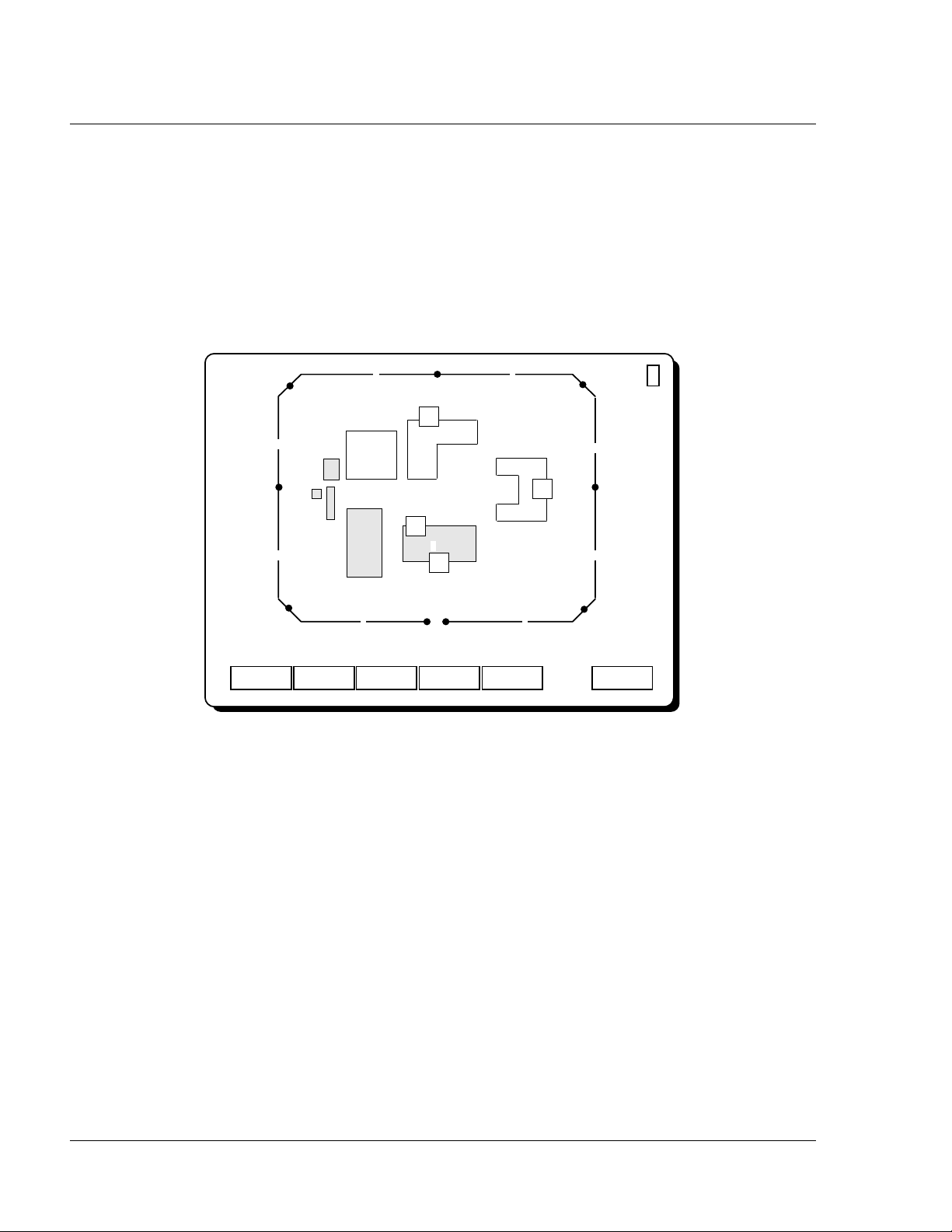
Senstar 100 screen display
Within the Operator menu, screens display the site maps. The maps show
the sensor locations and the status of the sensors. Other information on
the display includes prompts or messages to the user, and a line of
function boxes that are used to select other menus or activate commands.
Screens are divided into six main areas. Each area is described in detail on
the following pages.
An optional auxiliary VGA monitor is also available. This monitor displays
alarm information text that has been defined by the supervisor.
Helpfunction
The help function (?) always appears in the upper right-hand corner of
the display. It provides information on the functions currently available to
you. To get help, touch the ? function on the screen.
help function
main area
system prompt line
date/time
function line
alarm prompt line

introductiontoSenstar100
1-8 ••• operator’sguide
A sample help screen is shown below.
Mainarea
The main area of the screen displays either a map or text, depending on
which menu and function you’re using. On map displays, the map name
appears in the upper left corner. In most cases you can touch the map
name to get access to other maps in the system. On text displays, the page
number appears in the upper left corner. Touch the page number to
move to other pages. Alternatively, the function line commands can be
used.
Systempromptline
The system prompt line appears under the map. It displays:
• information about the current status of the system
• information about the function you’ve selected
• operator instructions
Clear Alrm Page 1 of 2
Remove a tamper, jam, fail or equipment alarm once the problem has
been fixed.
Display a list of Sensor or Equipment alarms. This function is
only displayed if the selected alarm type (Sensor/Equipment) has
more than one alarm to be cleared.
F1
Clear
F2
List
Choose Sensor to clear tamper, jam and fail alarms. This
function is only displayed if there are sensor alarms to be
cleared.
F3
Sensor
F4
Equipment
Page Quit
98/02/17
16:20:02
Choose Equipment to clear equipment alarms. This function is
only displayed if there are Equipment alarms to be cleared.

introductiontoSenstar100
operator’s guide • • • 1-9
Alarmpromptline
The alarm prompt line appears under the map. It displays:
• a location prompt that shows where a sensor is located (e.g., Main
entrance)
• a response prompt that tells you what to do in an alarm situation
(e.g., Call security)
Both prompts are displayed when an alarm occurs. The location prompt
also appears during normal processing.
Date/Time
The current date and time are always displayed in the lower right-hand
corner of the screen.
Functionline
The function line is located below the alarm prompt line.
The function line is the menu of available functions. You select a function
by touching it on the screen.
A highlighted function indicates that it has been selected and is enabled.
Sometimes the screen displays a highlighted function and the ↓and ↑
scrolling functions. This indicates that you use the scrolling keys with the
highlighted function.
For example, if the Page function is highlighted and the ↓and ↑boxes
appear, it means that there is more than one page to view. You use the ↓
function to view the next page, and the ↑function to view the previous
page.
introductiontoSenstar100
1-10 ••• operator’sguide
Maps and map symbols
Maps provide a visual display of an area or site, and indicate the status of
any sensors protecting that area. The maps are viewed in the Operator
menu and displayed during alarm processing. When an alarm occurs, the
map on which the alarm is located is automatically displayed.
The maps show:
• the sensors that provide detection for the site
• the zones where the sensors are located
• identifying information such as buildings, roadways, rooms, doors,
etc.
Concealedmaps(option)
Senstar 100 contains a feature that allows maps to be concealed from
operator view. This feature is only available if you have multiple control
units, a dual system (two Senstar 100 systems – two control units), and/or
a Sennet control panel(s) connected to the system. This feature allows
the Senstar 100 systems and Sennet control panels to operate as
independent consoles, each with its own set of maps.
?
Operator Menu>
G1 2
3
4
5
6
7
8
9
DOR
VOL
Main Campus
1
1
1
Checklist Test Acc/Sec Clear Alrm Logoff
Map Step
DOR
DOR
1
98/02/17
16:20:02

introductiontoSenstar100
operator’sguide • •• 1-11
Maps concealment status is determined at the Supervisor menu. The
function prevents specified maps from being displayed on a specific
control unit in a dual system. If a map has been concealed at a control
unit, you will not be able to view it at that control unit, and you will not
be able to process any alarms associated with the concealed map.
A map can never be concealed on all control units at the same time. If one
Senstar 100 system fails, the map concealment function is automatically
disabled. All maps are automatically displayed on the other system. When
the failed unit becomes available, the map concealment function is
automatically enabled, and the map concealment status reverts to the last
configuration saved in the Supervisor menu.
If all maps are concealed on a control unit, the Operator menu will not be
accessible on that system.
Monitoredmaps
Monitored map status is determined at the Supervisor menu. If a map is
configured to be monitored at a control unit, alarms can be viewed at that
control unit, however the alarms cannot be processed at the monitored
location initially. The alarms are presented at the control unit where they
are configured to be posted. If they are not processed within the set
timeout period, the alarms are presented at the monitored location for
processing.
Sensorlabelsandsymbols
The various types of sensors that are used to protect an area or site are
represented by labels and symbols on the site maps.
Each sensor is assigned a label up to three characters in length (e.g.,
Sentrax = SX, door sensor = DOR). The label might be surrounded by a
symbol (e.g., square or triangle). Your supervisor should tell you what
labels your sensors have.

introductiontoSenstar100
1-12 ••• operator’sguide
When several sensors provide coverage for one zone (maximum three
sensors per zone), their labels are displayed in the same symbol. Only the
first character of each sensor label is displayed in the symbol.
A sensor’s label and symbol are always displayed on the site map when:
• the sensor has generated an alarm
• the sensor has been accessed (i.e., alarms will not be sent to the
operator)
• the equipment that the sensor is connected to has failed
A sensor’s label and symbol might also be displayed on the site map when
the sensor is secure (i.e., fully operational).
If the system is configured to display detection alarm status, a sensor with
a detection alarm will display a flashing sensor label as long as the alarm
is present on the sensor.
Zonelabelsandsymbols
Site maps are divided into zones which represent the area covered by one
to three sensors. Each zone has a label of up to three characters. This
label is usually a number, but it can include letters. The zone label
appears above the sensor symbol.
Each zone might be surrounded by a zone symbol, which represents the
area of detection. The symbol appears either as a line or a polygon.
SX
Single-sensor zone
one sensor SDF
Multiple-sensor zone
3 sensors
(SX, DOR, FN)

introductiontoSenstar100
operator’sguide • •• 1-13
Groups
The zones on a map might be grouped together based on common
elements.
For example, all the zones along the perimeter of a site might be placed
in a group called the ‘Outer Perimeter’. This decision is made when the
maps are designed.
The Group feature makes certain operations easier (e.g., CCTV Setup,
Access/Secure) because it allows you to perform operations on the whole
group, rather than zone by zone.
?
Operator Menu>
G1 2
3
4
5
6
7
8
9
DOR
VOL
Main Campus
1
1
1
Checklist Test Acc/Sec Clear Alrm Logoff
Map Step
DOR
DOR
1
98/02/17
16:20:02
zone label
sensor symbol
sensor label
zone symbol (for zone 2)

introductiontoSenstar100
1-14 ••• operator’sguide
Equipmentlabelsandsymbols
Each item of equipment in your system is assigned a three-character label
that consists of a two-character abbreviation and the equipment number.
The equipment label appears in a rectangular symbol on the map. Some
equipment labels are shown in the table below. Your supervisor should
tell you what equipment labels you have.
Device Label
Control unit (main) CU1
Control unit (mate) CU2
Video switcher VS1
Control Module CM#
Interface Unit IU#
Sennet network SN#
Starcom SC#
DAVID Chassis DV#
Video Controller VC#
Fiber Sensys FS#
FOIDS 3000 DX FI#
Custom device handler CH#

introductiontoSenstar100
operator’sguide • •• 1-15
Equipmentcomponentlabelsandsymbols
Some items of equipment have component cards associated with them.
Each component card is assigned a four-character label consisting of a
two-character abbreviation and a two-character card number. The
component card label and the associated equipment label appear in a
rectangular symbol on the map, for example:
The component card labels are shown below.
Component card Label
Control Module Transceiver Module TM##
Perimitrax Sensor Module SM##
Sennet network Transponder Units TU##
Sennet network Large Transponder Units TU##
Sennet network Control Panels CP##
Fiber Sensys FC##
CM1
TM02
Control Module #1
Transceiver Module #2

Table of contents
Other Senstar Stellar Security System manuals


