Yacht Devices YDAB-01 User manual

User Manual
Alarm Button YDAB-01
also covers models
YDAB-01N, YDAB-01R
Firmware version
1.08
2022

Contents
Introduction 4
Warranty and Technical Support 5
I. Specication 6
II. Device overview 8
III. Device Installation and Connection to NMEA 2000 12
IV. Conguration with External Button 15
V. Conguration with Installation Description Strings 16
VI. Control from a MFD with CZone Support 25
VII. Built-in LED Signals 26
VIII. Firmware Updates 27
Appendix А. Troubleshooting 29
Appendix B. List of Sound Signals 31
Appendix C. List of External LED Signals 33
Appendix D. Engine and Transmission warnings 35
Appendix E. NMEA 2000 Messages 36
Package Contents
Device 1 pc.
This Manual 1 pc.
Button with Integrated LED 1 pc.
Sound Speaker 10W 4 Ohm Not supplied
NMEA 2000 Cable Not supplied

— 4 —
Introduction
Alarm Button (hereinafter Device) is a multifunctional NMEA 2000 device with wires for connection of an
external button with LED indicator (supplied with the Device) and a standard 4 or 8 Ohm sound speaker
(not supplied). It can be congured for the following functions:
• MOB button (default mode). Press and hold the connected button for 2 seconds to trigger a
sound alarm and send NMEA 2000 AIS MOB messages (emulating the MOB alerts received from
EPIRB and SART devices by NMEA 2000 AIS VHF) with the current GPS position. It sets the
mark of MOB position on a chart plotter. Press the button for a second time to cancel alarm and
stop transmission of MOB messages. Note that messages sent from the Device are not transmitted
externally via VHF or AIS, but are available to all NMEA 2000 devices on the vessel.
• Digital switching alarm unit. Device acts as an NMEA 2000 binary switch bank with 28
channels, each channel has a unique sound alarm and LED ashing sequence. Channels
(and corresponding sound alarms) can be turned ON or OFF from other equipment, including our
smart sensors, or from the screen of a modern chart plotter. Press the connected button to cancel
alarms.
• Engines monitoring unit. In this mode Device monitors NMEA 2000-integrated engines status
and parameters and triggers an alarm upon reception of engine waring ags or if certain engine
parameter goes out of range. This mode is very useful if an existing engine instrumentation does not
produce an audible ararm or is broken.
Device mode and audio signal level can be congured via connected button. More settings can be congured
with commands sent to the Device via the installation description strings (hardware and software from
Yacht Devices, ActiSense or Maretron is required).
The Device has a built-in a 10W amplier and current consumption during the audio playback may exceed 1
Ampere. Therefore, it is recommended to connect the Device near the NMEA 2000 power cable or connect
an additional power cable to the backbone socket next to the Device.
Thank you for purchasing our product and happy voyages!

— 5 —
Warranty and Technical Support
1. The Device warranty is valid for two years from the purchase date. If the Device was purchased in a
retail store, the sale receipt may be requested when applying for a warranty claim.
2. The Device warranty is terminated in case of Manual instructions violation, case integrity breach, or
repair or modication of the Device without manufacturer’s written permission.
3. If a warranty request is accepted, the defective Device must be sent to the manufacturer.
4. The warranty liabilities include repair and replacement of the goods and do not include the cost
of equipment installation and conguration, neither shipping the defective Device
to the manufacturer.
5. Responsibility of the manufacturer in case of any damage as a consequence of Device operation
or installation is limited to the Device cost.
6. The manufacturer is not responsible for any errors and inaccuracies in guides and instructions
of other companies.
7. The Device requires no maintenance. The Device’s case is non-dismountable. In the event
of a failure, please refer to Appendix A before contacting technical support.
8. The manufacturer accepts applications under the warranty and provides technical support only via
e-mail or through authorized dealers.
9. Manufacturer`s contact details and a list of the authorized dealers are published on the website:
http://www.yachtd.com/.

— 6 —
I. Specification
Figure 1. Drawing of YDAB-01N and YDAB-01R models of Device
Our devices are supplied with dierent types of NMEA 2000 connectors. Models containing an "R" in the
sux of the model name are equipped with NMEA 2000 connectors and are compatible with Raymarine
SeaTalk NG. Models containing "N" in the sux are equipped with NMEA 2000 Micro Male connectors.
Device cable has ve wires to connect the sound speaker (not supplied with the Device) and an external push
button with integrated LED.

— 7 —
Device parameter Value Unit
Power supply voltage, from NMEA 2000 network 7..16 V
Reverse polarity protection (power supply) Yes —
Average current consumption without playback 50 mA
Average current during playback (sound 1, Appendix B; 13V / 4 Ohm) 200 mA
Maximum current during playback (sound 23, Appendix B; 13 V / 4 Ohm) 440 mA
Recommended speaker impedance 4..8 Ohm
Audio amplier output (8 Ohm load at 13V) 10 W
Load Equivalency Number 20 LEN
Built-in current limiting resistor for the external LED 200 Ohm
External LED power supply 3,3 V
Operating temperature range -40..+80 °С
Weight 37 g
Device case length (without connector) 54 mm
Cable length 400 mm
Yacht Devices Ltd declares that this product is compliant with the essential requirements of EMC
directive 2014/30/EU and radio and TTE directive 1999/5/EC.
Dispose of this product in accordance with the WEEE Directive. Do not mix electronic waste with
domestic or industrial refuse.

— 8 —
II. Device overview
Figure 2. Functional scheme

— 9 —
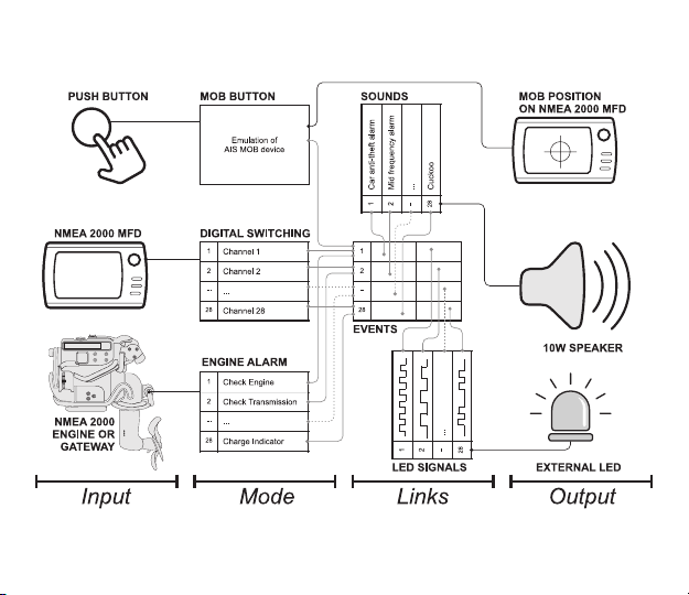
Device can function in one of three modes: MOB button, digital switching alarm unit or engine alarm unit.
1. MOB button mode
This mode is factory default. Press connected button for two seconds (button hold time can be changed in
settings) and Device will start sending NMEA 2000 MOB messages (PGNs 129038, 129802 and 127233),
using current GPS position data received from NMEA 2000 network. Multifunction displays, chartplotters
or navigational software (Expedition, OpenCPN) will place MOB mark on the chart, most of the displays
also will show popup MOB warning. In addition to that, Device will play a sound alarm (Sound 1, or custom
sound, linked with Event 1) and the external LED will start ashing, conrming that MOB alert is activated.
Press the button again to cancel MOB alarm and stop sending MOB PGNs.
For the MOB mark, Device uses MMSI number 972777XXX, where XXX is an incremental number from
000 to 999. This allows to set the mark next time when the previous MOB alert from the Device has been
cancelled or suppressed by the MFD user. Incremetation is used, because some plotters (for example,
Raymarine) do not react on MOB message, if MOB event with the same MMSI number has being already
received but was cancelled earlier.
Unlike a VHF distress button or activation of EPIRB, the signal is not sent out from the boat. The main
purposes of the Alarm Button are to wake up your crew with a sound alert and place the MOB position on
all chart plotters on board. Device is essential for you if you have no chart plotter near the helm, or if your
MFD has no hardware MOB button and you need it to comply with racing rules.
Device can be activated not only by pressing button, but also by MOB PGNs received from a NMEA 2000
AIS unit or chartplotter: PGN 127233 — "Man Overboard Notication (MOB)", PGN 129038 — "AIS Class
A Position Report" (with data eld "Navigational Status" = 14, SART ACTIVE), PGN 129802 — "AIS Safety
Related Broadcast Message" (with data eld "Safety Related Text" = "SART_ACTIVE" or "MOB_ACTIVE"
or "EPIRB_ACTIVE") and Raymarine proprietary PGN 65288 "SeaTalk Alarm" (with "alarm ID" = 38,
MOB).
Reaction on each PGN (127233|129038|129802) can be switched ON/OFF via YD:MOB_SRC command
(see Section V).
You can force device to react only to MOB PGNs with a specic MMSI numbers, included in a custom list
of your own EPIRB/MOB devices via YD:LIST command (see Section V). By default, device will react to
any MMSI.

— 10 —
2. Digital switching mode
Digital switching means that you can turn some loads (digital switching channels) ON or OFF via
chartplotter or software. For example, using a virtual button on the chart plotter screen you can turn on
navigation lights or a bilge pump.
In digital switching mode, Device allows you to turn ON and OFF any of its 28 internal "virtual" digital
switching channels from the chart plotter or from other digital switching equipment or software. Channels
can be managed by NMEA 2000 digital switching messages (PGN 127501 and 127502) or with proprietary
CZone messages (supported in most modern chart plotters, see the Section VI).
In NMEA 2000, digital switching devices are identied on the network by their bank number (can be
changed with YD:BANK command, see Section V). Channels on devices with the same bank number will be
turned ON or OFF synchronously by external equipment, this allows simultaneous activation of multiple
Alarm Buttons with the same function installed at dierent places on the boat.
Temperature, pressure and humidity sensors from Yacht Devices can be set up to turn target digital
switching equipment channels ON or OFF when the measured value is too high or too low. For example,
the Digital Thermometer can trigger an alarm on the Alarm Button when the temperature in an engine
room or live well is too high.
Our NMEA 2000 Wi-Fi Gateway or NMEA 2000 Wi-Fi Router allows to manage digital switching channels
via web browser; it can be used to trigger an alarm remotely, say, from the cockpit, to notify the crew or
scare a thief over the Internet.
Device also can receive and process proprietary Raymarine Seatalk Alarm messages (PGN 65288). Usually,
such messages are sent by Raymarine chart plotters. By default, processing of SeaTalk Alarms is disabled,
you can enable them using command YD:ALARM (see the Section V).
3. Engine alarm mode
In this mode, Device will activate various alarms upon reception of engine and transmission warnings (via
PGNs 127489 and 127493). You can also set up the Device to activate alarms on abnormal values of engine
revolutions, coolant temperature, oil and boost pressure. For example, you can program Device to activate
an alarm when engine revolutions exceed 3000 RPM for 30 seconds or more.

— 11 —
List of supported engine and transmission warnings is available in Appendix D. One Device can handle
events from all engines, or you can link it to a particular engine by NMEA 2000 engine instance. For
example, you can use two separate Devices (each one with its own dedicated speaker), one for port
(instance 0) and another for starboard (instance 1) engine.
4. Events, channels, sounds, ash sequences and links between them
You can congure sound alarms and external LED signals linked to dierent events. In MOB mode, only the
event with number 1 is used. In other modes, all 28 events (with numbers from 1 to 28) are associated with
28 digital switching channels or 28 supported engine and transmission warnings.
The Device memory contains 28 pre-recorded sound signals (see the Appendix B) and 28 LED ashing
sequences (see the Appendix C). In factory default settings, the sound signal number 1 and ashing
sequence number 1 are linked to event 1 and so on.
You can listen to pre-recorded sounds and look at LED ashing sequences using YD:PLAY and YD:LED
commands and set desired sound and ashing sequence for each event using YD:LINK command
(see the Section V). To disable or enable the event use YD:EVENT command.
If dierent events occur at the same time, event with lowest number will have highest priority,
Device will play sound and show LED ashing sequence linked with this event.
In engine alarm mode, pressing the button will suppress the current event for 30 seconds (time can be
changed in settings) for all engines. If multiple engine warnings occurs at the same time, the next event
will be activated.
In digital switching mode, connected button either turns channel/event 1 ON/OFF (channel/event number
can be changed in settings) or if multiple channels/events were already turned ON, each button press will
turn OFF an active channel/event, in order from lowest to highest priority.
For example, if you turn ON channels 1, 2 and 4 from external digital switching control equipment, Device
will play the sound and show LED sequence corresponding to the event 1. When you press the button,
channel 1 will be turned OFF and the Device will play the sound and show LED sequence corresponding
to the event 2. Next button press will turn OFF channel 2 and Device will play the sound and show LED
sequence corresponding to the event 4. Next button presses will turn OFF channel 4.

— 12 —
III. Device Installation and Connection to NMEA 2000
Figure 3. Device connection

— 13 —
Device requires no maintenance. When deciding where to install Device, choose a dry mounting location.
Avoid places where the Device can be ooded with water, this can damage it.
1. Connecting to NMEA 2000
Device can be directly plugged into to the network backbone connector. YDAB-01N model can also be
connected via standard "DeviceNet NMEA 2000 Micro" drop cable. Before connecting the Device, turn
OFF the bus power supply. Refer to the following documentation if you have any questions regarding the
conenctors and other NMEA 2000 backbone components installation requirements:
• SeaTalk NG Reference Manual (81300-1) for Raymarine networks
• Technical Reference for Garmin NMEA 2000 Products (190-00891-00) for Garmin networks
Note that Device is powered from the NMEA 2000 backbone and consumes up to 1 Ampere during
the playback, thus it is recommended to conenct the Device close to the NMEA 2000 power cable or add an
extra power tap from the battery near the connection point.
After connecting the Device, close connection lock to ensure water resistance and reliability. Device has a
built-in LED which ashes red or green. After powering NMEA 2000 network ON, Device’s built-in LED
will start ashing (see Section VII).
2. Connection of the external button and LED
Figure 4. Button terminals and electrical scheme

— 14 —
You can use supplied button or any momentary push-button you like that matches your boat’s interior.
Waterproof IP67 buttons of this type with integrated LED of various colours are widely available from
well-known international suppliers like DigiKey Electronics (www.digikey.com), Mouser Electronics
(www.mouser.com) and others. For example, Mouser part number 123-82-4151.1153 is an IP67 stainless
steel 16mm momentary push-button with white ring illumination (LED 12V, AC/DC).
Device provides 3.3 Volts to the external LED wire (YELLOW) and has a 200 Ohm built-in current-limiting
resistor (you can connect the LED directly to wires). Buttons with LEDs rated for 12 Volt will be brighter
than buttons rated for 24 Volt (actually they dier by current-limiting resistor inside). Buttons with LED
rated for 5 Volt and 3.3 Volt are recomemnded, also widely available.
YELLOW wire of the Device must be connected to LED’s anode (+), the BLUE wire must be connected to
the button, CLEAR wire must be shared between the LED’s cathode (-) and the second button terminal.
Terminals of the button supplied with the Device are shown in Figure 4. It is mandatory to crimp
contacts, soldering is optional. Soldering joints must be protected from the environment with paint or
lacquer.
3. Connection of the sound speaker
Device has a built-in 10 Watt audio amplier and can output current up to 1 Ampere. The best performance
will be achieved with 4 Ohm speakers, the 8 Ohm speaker will sound a little quieter. Piezoelectric sound
emitters can also be used, but they may have adequate performance with tone signals only.
Device's RED wire should be connected to the "+" terminal of the speaker, and BLACK wire should be
connected to the "-" terminal of the speaker (see Figure 3). Sound volume can be adjusted in the settings.
(see Sections IV and V).
Note that Device audio amplier power rails are directly connected to NMEA 2000 power
rails — Device audio output is not galvanically isolated from NMEA 2000 power. Therefore,
do not connect any other equipment to Device audio output and make sure that speaker cable
is routed well in a way that prevents its accidental short (between wires themselves or to the
vessel's common ground).
For maximum possible NMEA 2000 power short protection connect device to backbone via "NMEA
2000 power isolator" tee (e.g. Garmin part number 010-11580-00) and power the device from a
separate NMEA 2000 power cable with dedicated fuse.

— 15 —
IV. Configuration with External Button
Conguration with the external button is limited and allows to change volume and set Device operation
mode (see the Section II). To enter conguration mode:
• in MOB button mode: quickly press the button 5 times;
• in other modes: hold the button for 5 seconds.
Device conrms entering of the conguration mode with a 5-second long signal of the external LED. Press
the button once during that LED signal to enter mode programming, or wait until the Device enters volume
programming after that LED signal.
In mode programming, external LED will continuously ash, depending on the current mode:
• 1 short ash: MOB button mode;
• 2 short ashes: digital switching mode;
• 3 short ashes: engine alarm mode.
In the volume programming:
• 1 short ash: 1% of volume;
• 2 short ashes: 20% of volume;
• 3 short ashes: 40% of volume;
• 1 long ash: 60% of volume;
• 2 long ashes: 80% of volume;
• 3 long ashes: 100% of volume.
Press the button to cycle between modes or volume levels.
To apply settings, do not press the button for 10 seconds, Device will save current settings and return to
normal operation mode.

— 16 —
V. Configuration with Installation Description Strings
Installation description strings are usually set by installers to specify the device location or to leave notes
or contact information. This can be done with professional PC software (with a hardware gateway to NMEA
2000 network) and it may be supported by some models of chart plotters. Please refer to your software or
chart plotter documentation for details.
Figure 5. Programming with CAN Log Viewer
Programming of the Device should not be performed at sea.

— 17 —
To program the Device, enter a special string starting with "YD:" to installation description eld 2 in the
Device properties. For example, "YD:DEV 1" (without quotes) will change the NMEA 2000 Device instance
to 1. If command (except "YD:RESET") is accepted by the Device, it will add "DONE" to entered text and
"YD:DEV 1 DONE" will be displayed in this installation description eld. If a command is entered without
the parameter(s), Device replies with the current value of the parameter(s).
In Figure 5 on the previous page, you can observe Device programming process with free CAN Log Viewer
software (to open this window, select "NMEA 2000 Devices" in "View" menu, refresh the list of devices,
select the Device and click "Properties" button). You can download this program (runs on Microsoft
Windows, macOS and Linux) at http://www.yachtd.com/downloads/, Yacht Devices NMEA 2000 Wi-Fi
Gateway, Yacht Devices NMEA 2000 Wi-Fi Router or Yacht Devices NMEA 2000 USB Gateway is required
to connect the PC and CAN Log Viewer to NMEA 2000 network.
CAN Log Viewer also allows you to modify the NMEA 2000 device instance by entering a value in the
dedicated eld. After entering the "Device Instance" value (Figure 1, "Address Claim" settings group) click
the "Update" button to apply changes and the value in the "Device Instance" eld will be changed to 1, and
"Installation Details 2" eld will be changed to "YD:DEV 1 DONE".
If you want to replace built-in sounds with your own custom sounds you should have CAN Log Viewer
version 1.30 or higher and Device rmware version 1.02 or higher. Click "More.." button at Properties page,
and the "Sound Uploader" window will open (see Figure 6 below).
You can replace built-in sounds 25-28; other sounds (1-24) cannot be replaced. If you need to replace the
sound for MOB event 1, you can upload your custom sound le to slot 25 and link the sound 25 to event 1
with command:
YD:LINK 1 SOUND 25
To upload new or replace an old sound select slot number, select audio le, and click "Upload le" button.
You can also adjust "Start delay" and "Replay delay" parameters (from 0.1 to 600 seconds with 0.1 second
intervals) with "Update delays" button. For example, if you need a "fog horn" alarm where a 5-second signal
should be automatically repeated each minute, set replay delay of 1 minute.

— 18 —
Note that sounds 25–28 cannot be restored to factory defaults with the "YD:RESET" command. You will
need to re-upload original sounds again. Device rmware archive contains "SOUND" subfolder where
copies of original sounds audio les are present. The last two digits in le name are the factory start delay
and replay delay settings.
Device can accept audio les only in specic format — mono 16-bit PCM WAV les with sample rate of
22050 Hz, and length from 0.1 to 13 seconds (from 4 to 688 kBytes). Yes, the slot size is limited and you will
not able to upload your favourite MP3 track. But 13 seconds is enough for a long phrase.
We recommend free Audacity software to make audio les (https://www.audacityteam.org/ works on
Windows, macOS and Linux). It allows clipping of les, adjusting the volume (Eect > Amplify...) and
saving in various formats. Make sure to set the "Project Rate" to 22050 Hz and save the le of type "WAV
Microsoft signed 16-but PCM".

— 19 —
Figure 6. Audio les uploading
Full list of commands is given in Table 1. Parameters in square brackets can be omitted to get the current
setting value from the Device.

— 20 —
Table 1. Special strings
String format Examples Description
System commands
YD:RESET Reset all settings to factory defaults.
YD:DEV [0..255] YD:DEV 0 Set NMEA 2000 device instance value
(0 - 255). Factory setting 0.
YD:SYS [0..15] YD:SYS 0 Set NMEA 2000 system instance value
(0 - 15). Factory setting 0.
YD:PGN <pgn> [interval
| OFF]
YD:PGN 126993 60000
YD:PGN 127501 2000
Set transmission interval for PGN 126993
(Heartbeat) or 127501 (Binary Status Report)
in milliseconds. Values from 50 to 60 000 (1
minute) are allowed. OFF or 0 disables PGN
transmission.
Commands available in all modes
YD:MODE [MOB | DS |
ENGINE]
YD:MODE MOB Set operation mode. Device will be rebooted
after two seconds. Factory setting is MOB.
Note, that NMEA 2000 device class and
function will be changed after reboot, and you
may need to refresh NMEA 2000 devices list
in the software or on a chartplotter.
YD:PLAY [0..28] YD:PLAY 1 Play sound of specied number (1 – 28) or
stop playback (0). See Appendix B.
YD:LED [0..28] YD:LED 1 Show external LED indication sequence
of specied number (1 – 28) or stop LED
indication (0). See Appendix C.
This manual suits for next models
2
Table of contents