SENSTAR FPS-3 Original operating instructions

FPS System
Fence Protection System
G2DA0302-001, Rev A
First edition
September 15, 2009
FPS-3
Installation &
Operation Guide

Senstar Corporation
119 John Cavanaugh Drive
Carp, Ontario
Canada K0A 1L0
Tel: +1 (613)-839-5572
Fax: +1 (613)-839-5830
Website: www.senstar.com
Email address: info@senstar.com
G2DA0302-001, Rev A
First edition
September 15, 2009
Senstar is a registered trademark, and the Senstar logo is a trademark of Senstar Corporation. Product names and Company
names used in this document are included for identification purposes only, and are the property of, and may be trademarks of,
their respective owners. Copyright © 2009 Senstar Corporation. All rights reserved. Printed in Canada.
The information provided in this guide has been prepared by Senstar Corporation to the best of its ability. Senstar Corporation is
not responsible for any damage or accidents that may occur due to errors or omissions in this guide. Senstar Corporation is not
liable for any damages, or incidental consequences, arising from the use of, or the inability to use, the software and equipment
described in this guide. Senstar Corporation is not responsible for any damage or accidents that may occur due to information
about items of equipment or components manufactured by other companies. Features and specifications are subject to change
without notice. Any changes or modifications to the software or equipment that are not expressly approved by Senstar
Corporation void the manufacturer’s warranty, and could void the user’s authority to operate the equipment.
Senstar’s Quality Management System is IS0 9001:2000 registered.

Limited Warranty
a) The Company warrants that the electronic components of the products manufactured by the Company are free from all
manufacturing defects. The Company's warranty does not extend to the performance of the products, which may vary depending
on environmental conditions, use and installation practices. The Company's liability under this warranty shall be limited to, at its
option, either repairing or replacing the defective components of the products or granting a credit for the products or parts thereof.
The Company's liability shall apply only to products which are returned to the factory or authorized repair point, transportation
charges prepaid by the Buyer within one (1) year from the shipment date of the product from the Company and which are, after
examination, disclosed to Company's satisfaction to be defective due to defects in workmanship and/or materials. This warranty
shall not apply to any products which have been installed, repaired or altered by other than personnel certified by the Company, or
to products which have been subject to physical or electrical abuse, misuse, or improper storage or to products which have not
been used or maintained in compliance with any applicable recommendations of the Company. This warranty does not apply to
any parts or components of the products, which are normally consumed in operation, including but not limited to batteries, fuses
and light bulbs.
b) The Company specifically disclaims any and all warranties, expressed or implied, including but not limited to any warranties
or merchantability or fitness for a particular purpose. Under no circumstances be it due to a breach ofwarranty or any other
cause arising out of the performance or non-performance of the Product shall the Company be liable to the Buyer for incidental or
consequential damages, including but not limited to: lost profits, loss of property due to the freight, plant downtimes, or suits by
third parties.

5
INSTALLATION AND OPERATION INSTRUCTIONS — FENCE PROTECTION SYSTEMS
CONTENTS
PAGE
1QUICK START...................................................................... 1
2GENERAL ...........................................................................10
3THEORY OF OPERATION .................................................. 11
4FENCE CONDITIONS .........................................................14
5INSTALLATION ..................................................................18
6SYSTEM START UP AND TESTING ....................................45
7MAINTENANCE/TROUBLESHOOTING ............................. 52
ADDENDUM I – FIELD PERFORMANCE ANALYZER ................... A-1
iv

INSTALLATION AND OPERATION INSTRUCTIONS — FENCE PROTECTION SYSTEMS
v
LIST OF FIGURES PAGE
Figure 1 Typical MX-5300/FPS System Connections ..... 2
Figure 2 Fence Mounted FPS Dual Zone Pre-Amp ......... 3
Figure 3 Cable Tie Installation................................................ 4
Figure 4 Dual Zone Pre-Amp Cable Connections ........... 4
Figure 5 MPS-4100 Microwave Installation....................... 5
Figure 6 MPS Connections to FPS-3 via
Dual Zone Relay Input Card................................... 6
Figure 7 MX-5300 Power Supply Connections ................ 7
Figure 8 Central Controller Connections ........................... 8
Figure 9 MX-5300 Loop Connections.................................. 9
Figure 10 FPS-3 System .............................................................. 10
Figure 11 Alarm Zone Connections ....................................... 12
Figure 12 Block Diagram ............................................................ 13
Figure 13 Loose Fabric at Fence Posts ................................... 14
Figure 14 Loose Fabric at Diagonal Stiffeners .................... 14
Figure 15 Loose Fabric at Wire Stiffeners ............................. 15
Figure 16 Dangling Barbed Wire ............................................. 15
Figure 17 Improperly Secured Brackets................................ 15
Figure 18 Missing Vertical Locking Posts.............................. 15
Figure 19 Excessive Play............................................................. 16
Figure 20 Loose Chain and Lock.............................................. 16
Figure 21 Roller and Rail Play................................................... 16
Figure 22 Signs Not Securely Attached................................. 16
Figure 23 Fence-mounted Pre-amp ....................................... 19
Figure 24 Pre-Amp Remote Mounting .................................. 21
Figure 25 Pre-Amp Pedestal Mounting................................. 22
Figure 26 Unreeling Cable ......................................................... 23
Figure 27 Cable Tie Installation................................................ 24
Figure 28 Transducer Cable Around Fence Post ................ 25
Figure 29 Transducer Cable Service Loop ............................ 25
Figure 30 Increasing Transducer Cable Sensitivity ........... 26
Figure 31 Zone Overlap .............................................................. 27
Figure 32 Helisensor/Sensor Cable Termination-
Single Run .................................................................... 30
Figure 33 Helisensor/Sensor Double Run Installation/
Termination ................................................................. 31
Figure 34 Transducer Cable Routing in Condulet ............. 32
Figure 35 Transducer Cable Connection .............................. 32

7
INSTALLATION AND OPERATION INSTRUCTIONS — FENCE PROTECTION SYSTEMS
LIST OF FIGURES PAGE
Figure 36 End-of-Line Termination ......................................... 33
Figure 37 Splice Termination .................................................... 33
Figure 38 End-of-Line Termination With 2 Megaohm
Resistor.......................................................................... 33
Figure 39 EOL Condulet Attached To Fence........................ 34
Figure 40 Condulet Splice Attached To Fence.................... 34
Figure 41 Condulet “G”Attached To Fence .......................... 34
Figure 42 Transducer Service Kit ............................................. 36
Figure 43 Transducer Cable Preparation .............................. 36
Figure 44 Hinged Gate Installation......................................... 37
Figure 45 Telegate Installation ................................................. 38
Figure 46 Telegate Support Post Location........................... 39
Figure 47 MPS Microwave System .......................................... 41
Figure 48 Pre-Amp Cable Connections ................................. 42
Figure 49 Central Controller Cable Connections ............... 43
Figure 50 Dual Zone Relay Input Card Wiring .................... 44
Figure 51 Interface Board Connections and Controls ..... 46
Figure 52 Dual Zone Card.......................................................... 46
Figure A-1 Field Performance Analyzer ................................ A-3
LIST OF TABLES
Table 1 Sensor Cable Capacitance...................................... 13
Table 2 Field Measured Gain and Count Settings......... 51
Table 3 FPS-3 Troubleshooting Table ................................ 56
Table 4 Interface Board Fault Isolation Matrix................ 58
vi

1
INSTALLATION AND OPERATION INSTRUCTIONS — FENCE PROTECTION SYSTEMS
FENCE PROTECTION SYSTEMS
1 QUICK START
Qualified technicians may follow these simplified procedures to install and test the FPS-3 Fence
Protection System.Prerequisites for using the quick start procedures are:
• Attendance at one or more Magal-SenstarFPS-3 training class.
• Prior MX-5000 or MX-5300 field installation experience.
Before proceeding, VERIFY that you have a complete site layout showing zone extents, processor
locations, and conduit interconnections. If you are not familiar with any of the procedures described in
this section, refer to the appropriate manual for more detailed information.
IMPORTANT PROCEDURES
Throughout the installation it is very important that certain procedures are observed:
Install ground rods and proper grounding at the MX-53OO,all FPS-3 fence-
mounted pre-amps, and all microwave locations.
Use only the approved multiconductor shielded cable for connecting the MX-
5300 FPS-3 Central Controller to the FPS and MPS units.
Terminate wiring and shields exactly as shown. Improper terminations will cause
system noise and degrade performance.
The FPS-3 Central Controller must be installed within 100 feet of the MX-5300.

INSTALLATION AND OPERATION INSTRUCTIONS — FENCE PROTECTION SYSTEMS
2
Installation
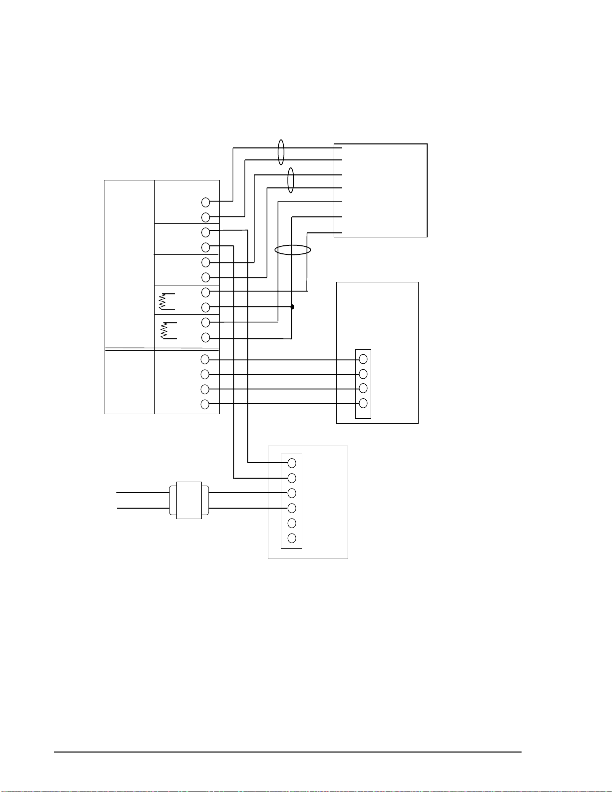
Figure 1 shows the typical wiring interconnection of components.
•The interconnect wiring should be run in conduit, either underground or along the base of the
fence.
•The interconnect cable must be an approved two-pair, 24-gauge, individually shielded twisted
pair low capacitance cable, with high density polyethylene jacket, such as the Magal-Senstar
FPS Interconnect Cable or factory-approved equal.
Figure 1. Typical MX-5300 / FPS System Connections

3
INSTALLATION AND OPERATION INSTRUCTIONS — FENCE PROTECTION SYSTEMS
Mount each FPS-3 Dual Zone Pre-Amp processor as shown in Figure 2.
• Use metal brackets or Unistrut-type mounting material to provide a solid backing. A fence post
will provide a solid mounting.
• Arrange the conduit/control wiring entrance as shown.
• Install a copper-clad ground rod at each processor location, and connect a minimum 8-gauge
ground wire to the processor bolt as shown. IMPORTANT: Connect the ground wire directly to
the enclosure stud as shown.
Figure 2. Fence Mounted Dual Zone Pre-Amp
Ground MUST be
attached to grounding
stud here.
Unistrut type
mounting
Approx. 12" apart
on center.
Install copper-clad
ground rod per
National Electrical Code
To FPS-3 Central
Controller
Watertight com-
pression fittings
GROUND ROD
CONNECTION
FPS-3
DUAL ZONE
PRE-AMP

INSTALLATION AND OPERATION INSTRUCTIONS — FENCE PROTECTION SYSTEMS
4
Run the sensor cable from each FPS-3 dual zone pre-amp as shown in Figures 2 and 3.
NOTE: Your installation may utilize either standard "black" sensor cable or Helisensor.
Observe special requirements for each type sensor.
• Attach the sensor cable to the
fence at approximate 12-inch
intervals with black UV cable ties
as shown in Figure 3. Use ONLY
the approved black UV-protected
cable ties.
• Provide service loops every 50 feet
and increased sensitivity loops at
each corner or end post. Provide
cable overlap at adjacent zones.
Install TSK termination boxes at
each sensor end-of-line (single-run
cable) and splices if necessary.
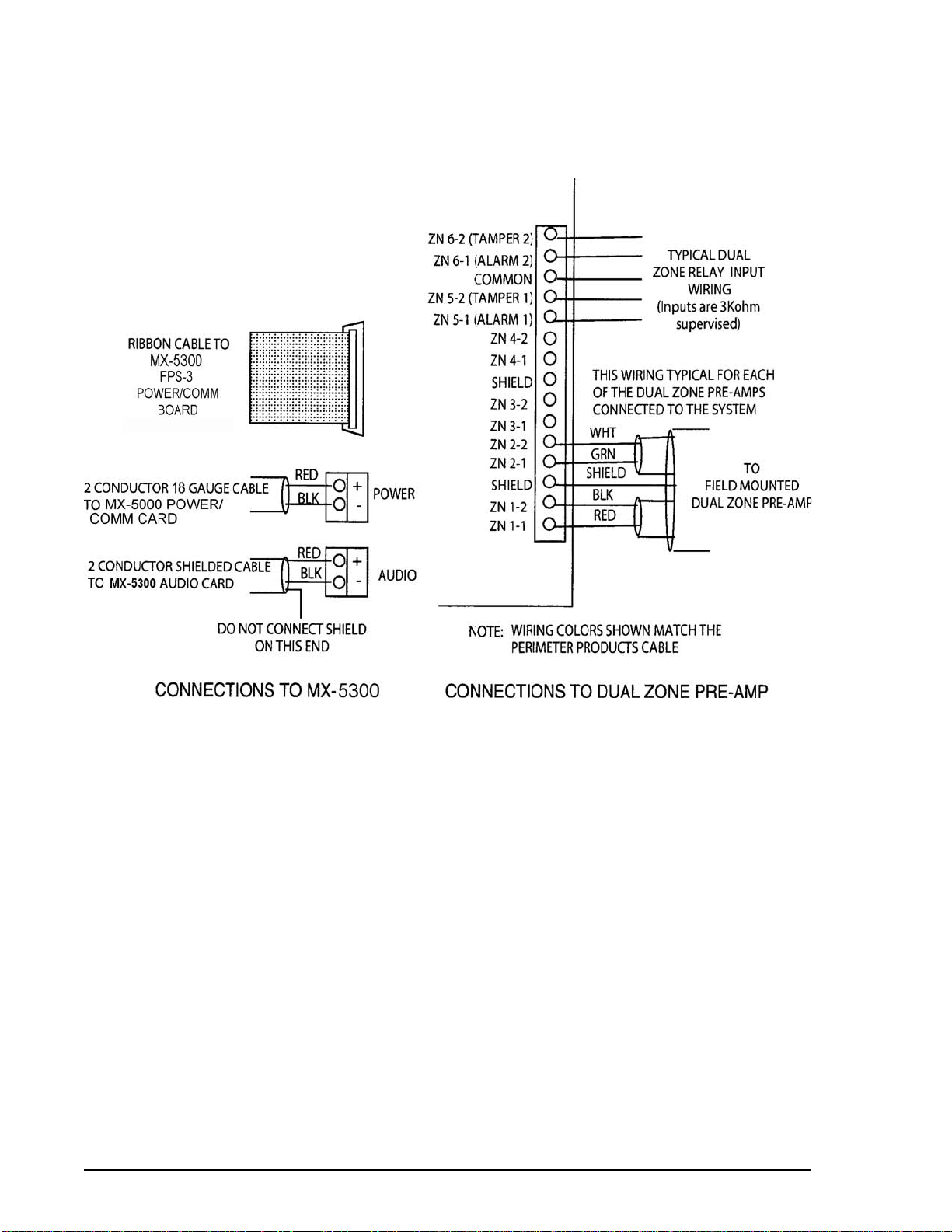
• Connect each sensor cable to the
Pre-Amp as shown in Figure 4.
• Connect the control wiring to each
dual zone pre-amp as shown in
Figure 4.
Figure 3. Cable Tie Installation
Figure 4. Pre-Amp Cable Connections
Approx. 12"
REMOVABLE
TERMINAL BLOCKS
DUAL ZONE PRE-AMP.
CIRCUIT BOARD
1 2
CENTER
SHIELD
1 2 1 2
CENTER
SHIELD
1 2
SHIELD
ZN 1-1
ZN 1-2
ZN 2-1
ZN 2-2
SEE WIRING
DETAIL
WIRING TO
CENTRAL CONTROLLER
SHIELD
ZN 1-1
ZN 1-2
ZN 2-1
ZN 2-2
RED
BLK
SHIELD
GRN
WHT
TO
CENTRAL
CONTROLLER
NOTE: WIRING COLORS SHOWN MATCH THE
Magal-Senstar CABLE
LEFT ZONE
SENSOR CABLE
RIGHT ZONE
SENSOR CABLE
Lightly shaded cables
indicate return sensor
cable terminations in a
double run installation
1 MEG 1 MEG

5
INSTALLATION AND OPERATION INSTRUCTIONS — FENCE PROTECTION SYSTEMS
Mount each MPS-4100 microwave unit (pair) as
shown in Figure 5.
•Install each piece of equipment generally as
shown.
Figure 5. MPS-4100 Microwave Installation
a
a
a
a
a
a
a
aa
a
aa
aaa
a
a
a
a
a
a
a
aa
a
a
a
a
a
a
a
a
a
aa
a
a
a
a
a
a
aa
a
a
a
a
a
a
a
a
a
aa
a
aa
aaa
a
a
a
a
a
a
a
aa
a
a
a
a
a
a
a
a
a
aa
a
a
a
a
a
a
aa
a
a
a
a
a
a
a
a
a
a
a
MPS-4100 TRANSMITTER
MPS-4100 RECEIVER
To FPS-3 Central
Controller
INSTALLATION AND OPERATION INSTRUCTIONS — FENCE PROTECTION SYSTEMS
6
Figure 6. MPS Connections to FPS-3 via Dual Zone Relay Input Card
•Run interconnecting cables and connect as shown in Figure 6.
Position the FPS-3 Central Controller and the MX-5300 Control Unit in the control room as appropriate
for proper viewing and operation.
MPS 4100 TRANSMITTER
+DC OUT
RTN
AC IN
AC IN
BAT +
BAT -
UPS-PFI POWER SUPPLY
CLASS 2
TRANSFORMER
115V/60HZ 16.5 VAC
AUDIO +
AUDIO -
+12 VDC
COMMON
DATA/TEST +
DATA/TEST -
TAMPER
TAMPER
ALARM
ALARM
TB 1
MPS 4100 RECEIVER
3K
COMMON
+12V DC
TAMPER
TAMPER
TAMPER
TAMPER
COMMON
+12V DC
TB 2
AUDIO
ALARM
DUAL ZONE RELAY INPUT
CARD IN FPS-3 CENTRAL
CONTROLLER
TEST
3K
May select
3K at Tx or
N/C here
N/C output
or 3K output
and N/C at
Receiver
TAMPER
COMMON

7
INSTALLATION AND OPERATION INSTRUCTIONS — FENCE PROTECTION SYSTEMS
Connect the power supply transformer and battery as shown in Figure 7.
Figure 7. MX-5300 Power Supply Connections
INSTALLATION AND OPERATION INSTRUCTIONS — FENCE PROTECTION SYSTEMS
8
Field wiring connections to the FPS-3 Central Controller will be made as shown in Figure 8.
Figure 8. Central Controller Connections

9
INSTALLATION AND OPERATION INSTRUCTIONS — FENCE PROTECTION SYSTEMS
Figure 9. MX-5300 Loop Connections
Connections from the FPS-3 Central Controller to the MX-5300 will be made as shown in Figure 9.
Apply power to the MX-5300 and FPS-3 Central Controller by connecting the AC power first, then the
battery system. Perform initial programming to acknowledge initial alarms.
Perform initial testing of each zone using the self-test function and audio probe of the FPS-3 Central
Controller. Measure the optimum gain and count at each dual zone pre-amp using the MSI Field
Performance Analyzer (FPA). Perform fence quieting procedure if necessary.
Complete MX-5300 programming by performing the programming steps needed for your system. For
programming reference,refer to MX-5300 Installation Manual,Table 2.
Set the FPS-3 dual zone card gain switches for each zone based on your field measurements using the
FPA. Program the counts for each zone on the MX-5300.
Perform final testing, including climb test, in each zone as required by the system specifications.
1 2 3 4 5 6 7 8
LOOP 3
AUDIO
LOOP 2
AUDIO
Tie shield to
chassis ground lug.
2 pair shielded cable to
FPS-3 central controller.
AUDIO TERMINAL BOARD
TB 2
FPS-3 POWER/COMM BOARD
TB 3
AUDIO +
COMMON
LOOP 1
AUDIO
1 2
-+
POWER/COMM
BOARD
25 conductor ribbon cable
to FPS-3 central controller.
RED
BLK
BLK
RED

INSTALLATION AND OPERATION INSTRUCTIONS —FENCE PROTECTION SYSTEMS
10
2 GENERAL
Magal-Senstar manufactures a unique outdoor perimeter detection system called the FPS-3
Fence Protection System.The FPS-3 system consists of the fence-mounted transducer sensor cable
connected to the fence-mounted dual zone pre-amp and the FPS-3 Central Controller connected to
the MX-5300 Command and Display System. See Figure10.The FPS-3 system is designed for easy
installation and maintenance while providing superior detection if someone attempts to climb, lift the
fabric or cut through the fence.When the transducer cable is installed on the fence, the transducer
cable AND THE FENCE become the fence protection sensor system.
This manual covers all FPS-3 system installations. Just two FPS-3 models are required to accommodate
all types of installations:
FPS-3 Dual Zone Pre-Amp is used when installing standard fence mounted transducer sensor cable.
FPS-3H Dual Zone Pre-Amp is used when installing Helisensor cable.
The FPS-3 Central Controller and the MX-5300 Command and Display System are used in all FPS-3
system installations.
Figure 10. FPS-3 System

11
INSTALLATION AND OPERATION INSTRUCTIONS —FENCE PROTECTION SYSTEMS
3 THEORY OF OPERATION
Concept
When the Transducer Sensor Cable experiences small mechanical shocks or vibrations, an electrical
signal is generated between the center conductor and the outer shield.The Signal Processor then
analyzes that signal and makes the determination as to whether the vibration is intruder related or
from natural causes such as wind, rain, hail, etc. Should there be an intruder, the signal processor will
generate an alarm output.
The FPS-3 system features the Magal-Senstar exclusive EDAPT alarm processing system.The
EDAPT system utilizes a computer modeling program to analyze the fence activity of all alarm zones
and automatically adjust the alarm threshold based on current fence conditions and historical data.
Alarm processing
The MSI FPS system is a strain-sensitive cable sensor system, meaning that a mechanical disturbance in
the fence causes a small strain on the sensor cable that is converted to an electrical signal.
The sensor cable is a small coaxial cable specially manufactured with a permanent electrical charge
throughout its entire length.Any movement in the fence causes a small voltage to appear at the
sensor cable output. Magal-Senstar tests every foot of the sensor cable to verify that the alarm
sensitivity will be uniform over the entire length.
The sensor cable connects to the FPS-3 dual zone pre-amp mounted on or near the fence at the
beginning of the detection zone.The mechanical disturbance detected by the sensor cable is sent to
the dual zone pre-amp. Each FPS-3 dual zone pre-amp contains two independent zones of perimeter
protection (see Figure 11).The typical FPS-3 dual zone pre-amp will have up to a 1000-foot alarm zone
running in each direction.
1. The dual zone pre-amp sends the alarm and tamper information to the FPS-3 Central Controller
for processing. All alarm event processing is accomplished at the FPS-3 Central Controller, away
from the harsh outdoor environment of the fence.The Central Controller contains individual
plug-in cards for alarm processing, system diagnostic lamps and a built-in test system that allows
you to test each zone.
2. The FPS-3 Central Controller forwards alarm event information to the MX-5300 Control Station.
The MX-5300 utilizes advanced EDAPT processing,which uses the alarm data in a unique calcula-
tion to best determine the occurrence of an actual alarm condition over the external physical
forces (wind, rain, etc.) and the aging conditions of the fence installation.
The dual zone pre-amp is capable of monitoring a transducer cable in excess of 1000 feet, depending
on the total capacitance of the cable attached to the sensor input. The graph,Table 1, indicates the
sensor cable capacitance relative to length. The maximum allowable capacitance is 100,000 pf. In
addition to the transducer cable,it is possible to use nonsensitive cable (30MNS) to connect transducer
cable to the processor as long as the maximum capacitance is not exceeded. This is sometimes desir-
able in cases where the processor is not located near the fence.

INSTALLATION AND OPERATION INSTRUCTIONS —FENCE PROTECTION SYSTEMS
12
The ultimate goal of the fence protection system is reliable detection of cutting and/or climbing with
minimum nuisance alarms. Since the FPS sensor system is mounted to the fence fabric, care must be
taken when installing and maintaining the fence. A fence installed to normal professional standards
will provide an acceptable basis for the FPS system. However, a fence improperly installed and/or
missing tie wires and clamps can cause nuisance alarms.
Figure 11. Alarm Zone Connections
FPS-3
DUAL ZONE
PRE-AMP.
END OF LINE
TERMINATION**
LEFT ZONE RIGHT ZONE
EARTH GROUND
WIRING TO FPS-3
CENTRAL CONTROLLER
END OF LINE
TERMINATION**
SENSITIVE
TRANSDUCER
CABLE
SENSITIVE
TRANSDUCER
CABLE
** Double runs of sensor cable
return to termination located
inside dual zone pre-amp.

13
INSTALLATION AND OPERATION INSTRUCTIONS —FENCE PROTECTION SYSTEMS
Table 1. Sensor Cable Capacitance
Figure 12. Block Diagram
TRANSDUCER
CABLE INPUT
FILTERS
OUTPUT TO
MX-5300
DIFFERENTIAL
AMPLIFIER
ALARM
EVENT
REGISTER
LINE
DRIVER
AMP.
THRESHOLD
DETECTOR
RECEIVER/
BUFFER
DATA
MANAGER
AUDIO
MANAGER
I/O
DECODER
ADDRES
S
SIGNAL
CONDITIONER
TEST
MANAGER
TEST
SELECT
ZONE PROCESSOR
INTERFACE BOARD
DUAL ZONE PRE-AMP
(field mounted)
500 1000 1500
50,000
100,000
T
RANSDUCER LENGTH - ft.
T
ypical FPS Transducer Cable Capacitance - pF
MAXIMUM
SENSOR LOAD
CAPACITANCE

INSTALLATION AND OPERATION INSTRUCTIONS —FENCE PROTECTION SYSTEMS
14
4 FENCE CONDITIONS
Fence Conditions
When the FPS Transducer Sensor Cable is installed on the fence, the sensor cable and the fence be-
come the fence protection system. In effect, the sensor cable listens to the fence to detect the signals
caused by climbing, jacking, or cutting the fence.
It is recommended that you walk the entire length of the fence line to determine if the fence requires
maintenance prior to installation. Grab the fabric between each and every line post, pull it to you, and
let it go. Listen to it! The fence can flex, but if you hear any bangs, clangs, etc., they can be a source of
nuisance alarms and should be corrected. Keep a log of any potential problems so they can be identi-
fied and repaired before the fence protection system is operational. Refer to Fence Quieting later in
this section.
Typical Source or Locations of Trouble Spots
The following photographs (Figures 13 through 22) show examples of the most common problems
found with fence installations.
Figure 13 Loose fabric at fence posts or
horizontal rails
Figure 14 Loose fabric at diagonal
stiffeners
Table of contents
Popular Protection Device manuals by other brands


FORESIGHT
FORESIGHT SP001 quick start guide

ACARiS
ACARiS HORSE PROTECTOR installation manual

Manson Engineering Industrial
Manson Engineering Industrial SSB-2180 user manual

3M
3M Peltor Optime H510A manual

i4Technology
i4Technology BugHunter DAudio bda-4 Voice user manual

Toshiba
Toshiba GRE110 instruction manual


