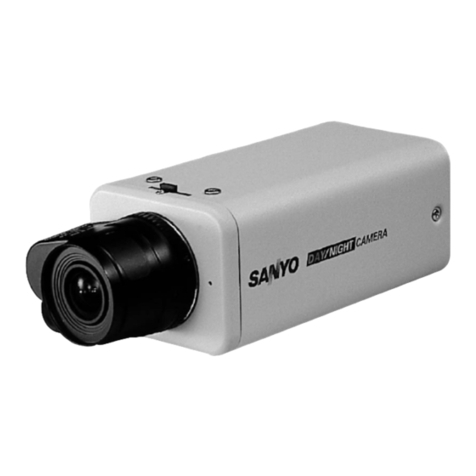
SenTech STC-C42A Owner's manual

Small Cubic Type
CCIR High-Resolutions
Monochrome Analog Camera
STC-C42A (1/2” CCD)
STC-C43A (1/3” CCD)
Product Specification

STC-C42A (1/2” CCD)
STC-C43A (1/3” CCD)
!
CAUTION
RISK OF ELECTRIC SHOCK
DO NOT OPEN
CAUTION:
TO REDUCE TH E RISK OF ELECTRIC SHOCK, DO NOT
REMOVE COVER (OR BACK). NO USER SERVICEABLE
PARTS INSIDE.
REFER SERVICING TO QUALIFIED SERVICE PERSONNEL.
The lightning flash with arrowhead
symbol, within an equilateral triangle,
is intended to alert the user to the
presence of uninsulated “dangerous
vo ltag e” wi thin the produ ct ’s
enclosure that may be of sufficient
magnitude to constitute a risk of
electric shock to persons.
The exclamation point within an
equilateral triangle is intended to alert
the user to the presence of important
operating and maintenance (servicing)
i nst ructi o ns in t h e l i te rat u re
accompanying the appliance.
!
Warning:
This equipment generates and uses radio frequency energy and if
not installed and used properly, I.e., in strict accordance with the
instruction manual, may cause harmful interference to radio
communications. It has been tested and found to comply with the
limits for a Class A computing device pursuant to Subpart J of Part
15 of FCCRules, which are designed to provide reasonable
protection against such interference when operated in a commercial
environment.
For U.S.A.
Warning:
This digital apparatus does not exceed the Class A limits for radio
noise emissions from digital apparatus set out in the Radio
Interference Regulations of the Canadian Department of
Communications.
For Canada
WARNING:
TO PREVENT FIRE OR SHOCK HAZARD, DO NOT EXPOSE
THIS APPLIANCE TO RAIN OR MOISTURE.
!
CAUTION
RISK OF ELECTRIC SHOCK
DO NOT OPEN
CAUTION:
TO REDUCE TH E RISK OF ELECTRIC SHOCK, DO NOT
REMOVE COVER (OR BACK). NO USER SERVICEABLE
PARTS INSIDE.
REFER SERVICING TO QUALIFIEDSERVICE PERSONNEL.
The lightning flash with arrowhead
symbol, within an equilateral triangle,
is intended to alert the user to the
presence of uninsulated “dangerous
vo ltag e” wi th in th e pro du ct ’ s
enclosure that may be of sufficient
magnitude to constitute a risk of
electric shock to persons.
The exclamation point within an
equilateral triangle is intended to alert
the user to the presence of important
operating and maintenance (servicing)
i nst ructi o ns in t h e l i te rat u re
accompanying the appliance.
!
Warning:
This equipment generates and uses radio frequency energy and if
not installed and used properly, I.e., in strict accordance with the
instruction manual, may cause harmful interference to radio
communications. It has been tested and found to comply with the
limits for a Class A computing device pursuant to Subpart J of Part
15 of FCCRules, which are designed to provide reasonable
protection against such interference when operated in a commercial
environment.
For U.S.A.
Warning:
This digital apparatus does not exceed the Class A limits for radio
noise emissions from digital apparatus set out in the Radio
Interference Regulations of the Canadian Department of
Communications.
For Canada
WARNING:
TO PREVENT FIRE OR SHOCK HAZARD, DO NOT EXPOSE
THIS APPLIANCE TO RAIN OR MOISTURE.
!
CAUTION
RISK OF ELECTRIC SHOCK
DO NOT OPEN
CAUTION:
TO REDUCE TH E RISK OF ELECTRIC SHOCK, DO NOT
REMOVE COVER (OR BACK). NO USER SERVICEABLE
PARTS INSIDE.
REFER SERVICING TO QUALIFIEDSERVICE PERSONNEL.
The lightning flash with arrowhead
symbol, within an equilateral triangle,
is intended to alert the user to the
presence of uninsulated “dangerous
vo ltag e” wi th in th e p ro du ct ’s
enclosure that may be of sufficient
magnitude to constitute a risk of
electric shock to persons.
The exclamation point within an
equilateral triangle is intended to alert
the user to the presence of important
operating and maintenance (servicing)
i nst ru cti o ns in t he l i te rat u re
accompanying the appliance.
!
Warning:
This equipment generates and uses radio frequency energy and if
not installed and used properly, I.e., in strict accordance with the
instruction manual, may cause harmful interference to radio
communications. It has been tested and found to comply with the
limits for a Class A computing device pursuant to Subpart J of Part
15 of FCCRules, which are designed to provide reasonable
protection against such interference when operated in a commercial
environment.
For U.S.A.
Warning:
This digital apparatus does not exceed the Class A limits for radio
noise emissions from digital apparatus set out in the Radio
Interference Regulations of the Canadian Department of
Communications.
For Canada
WARNING:
TO PREVENT FIRE OR SHOCK HAZARD, DO NOT EXPOSE
THIS APPLIANCE TO RAIN OR MOISTURE.
Safety Precautions
Product Precautions
Handle the camera with care. Do not abuse the camera. Avoid striking or shaking it. Improper handling
or storage could damage the camera.
Do not pull or damage the camera cable.
During camera use, do not wrap he unit in any material. This will cause the internal temperature of the
unit to increase.
Do not expose the camera to moisture, or do not try to operate it in wet areas.
Do not operate the camera beyond its temperature, humidity and power source ratings.
While the camera is not being used, keep the lens or lens cap on the camera to prevent dust or
contamination from getting in the CCD or filter area and scratching or damaging this area.
Do not keep the camera under the following conditions:
In wet, moist, and high humidity areas
Under hot direct sunlight
In high temperature areas
Near an object that releases a strong magnetic or electric field
Areas with strong vibrations
Use a soft cloth to clean the camera. Use pressured air spray to clean the surface of the glass. DO not
scratch the surface of the glass.

STC-C42A (1/2” CCD)
STC-C43A (1/3” CCD)
Contents
1
2-4
2
3
4
4
5
6
7
C. Dimensions (Camera with Tripod)…………………………………………………………………….
B. Dimensions (Tripod)……………………………………………………………………………………………
I. Specifications
A. Electronic Specs / Mechanical Specs / Environmental Conditions…………….
II. Dimensions
A. Dimensions……………………………………………………………………………………………………………..
B. Rear Panel Specifications…………………………………………………………………………………
1. Connector Pin Assignment……………………………………………………………………..
2. DIP Switch Settings…………………………………………………………………………………….
3. External Sync………………………………………………………………………………………………..
4. Gain Mode Setting……………………………………………………………………………………….
Specification Manual i Rev 1.1

STC-C42A (1/2” CCD)
STC-C43A (1/3” CCD)
I. Specifications
A. Electronic Specifications / Mechanical Specifications / Environmental Conditions
Specification Manual 1 of 7 Rev 1.1

STC-C42A (1/2” CCD)
STC-C43A (1/3” CCD)
B. Rear Panel Specifications
1. Connector Pin Assignment
12 Pin Connector Assignment
The connector type: HR10A-10R-12PB (Hirose) or equivalent
The camera settings can change by RS232C communication with No. 9 and 12.
Please refer the detail for the user’s guide.
12 Pin Connector
DIP Switch
External Sync (HD/VD) Signal
Impedance Switch
Gain Mode Switch
Manual Gain Pot
Figure 1
Figure 2
Specification Manual 2 of 7 Rev 1.1
Pin Assignment
*Note: Pin No.12 can be connected to GND
No. Internal sync External sysnc
1 GND GND
2 +12V DC +12V DC
3 VIDEO GND VIDEO GND
4 VIDEO OUT VIDEO OUT
5 HD GND HD GND
6 HD OUT HD IN
7 VD OUT VD IN
8 GND GND
9 TXD TXD
10 - -
11 - -
12 RXD (Note) RXD (Note)
Signal types

STC-C42A (1/2” CCD)
STC-C43A (1/3” CCD)
2. DIP Switch Settings (Refer to Dip Switch in Figure 1)
DIP Switch No. 1 to 4: Shutter Speed
DIP Switch No. 5 to 7 : No Function
DIP Switch No. 8: Gamma
DIP Switch No.9: Sync. System
DIP Switch No.10: Integration
1
2
3
4
5
6
7
8
9
0
O
N
Figure 3
Specification Manual 3 of 7 Rev 1.1

STC-C42A (1/2” CCD)
STC-C43A (1/3” CCD)
3. External Sync. (HD/VD) signal impedance setting (See External Sync. in Figure 1)
ON: 75Ohm termination
OFF: High impedance
4. Gain Mode Setting (See Gain Mode Switch in Fig. 1)
FIX: Fixed gain
MAN: Manual gain
The gain can be adjustable by the manual gain pot (See Manual Gain Pot in Fig. 1).
Specification Manual 4 of 7 Rev 1.1

STC-C42A (1/2” CCD)
STC-C43A (1/3” CCD)
II. Dimensions
A. Camera Dimensions
Unit: mm
Specification Manual 5 of 7 Rev 1.1

STC-C42A (1/2” CCD)
STC-C43A (1/3” CCD)
B. Tripod Dimensions
Unit: mm
Specification Manual 6 of 7 Rev 1.1
Tripod screw depth 5.5
2-M4 (P=0.7) depth 5.5
33.5
22(9)
24
12
4
9.5 9.5
(10.5)
(R13.8)
6.5
(10.5)

STC-C42A (1/2” CCD)
STC-C43A (1/3” CCD)
C. Camera with Tripod Dimensions
Unit: mm
Specification Manual 7 of 7 Rev 1.1

STC-C42A (1/2” CCD)
STC-C43A (1/3” CCD)
Revisions
Revision
Date (D/M/Y)
Changes
Name
Changes
1.0
26/10/2006
New Document
Sam Aimono
1.1
12/05/2008
Edited English
Michelle Campbell
Specification Manual Rev 1.1

STC-C42A (1/2” CCD)
STC-C43A (1/3” CCD)
Sensor Technologies America, Inc.
1345 Valwood Pkwy, Suite 320
Carrollton, Texas 75006-6891
TEL (972) 481-9223 FAX (972) 481-9209
URL http://www.sentechamerica.com/
Sensor Technology Co., Ltd.
7F, Harada Center Building
9-17, Naka cho 4chrome
Atsugi-city, Kanagawa
243-0018 Japan
TEL +81-46-295-7061 FAX +81-46-295-7066
URL http://www.sentech.co.jp/
Taiwan Sensor Technology, Inc.
3F-6, No. 9, Aiguo W, Rd,. Jhong Jheng District
Taipei City 100, Taiwan, R.O.C.
TEL 886-2-2383-2331 FAX 886-2-2370-8775
Other manuals for STC-C42A
1
This manual suits for next models
1
Table of contents
Other SenTech Security Camera manuals
SenTech
SenTech STC-A33A User manual
SenTech
SenTech STC-400 Series User manual
SenTech
SenTech STC-GE83A User manual

SenTech
SenTech STC-TB83USB-ASH User manual
SenTech
SenTech STC-SCS231POE Installation instructions
SenTech
SenTech STC-1100C User manual
SenTech
SenTech STC-CL500E User manual
SenTech
SenTech STC-400 Series User manual
SenTech
SenTech STC-GE33OX User manual
