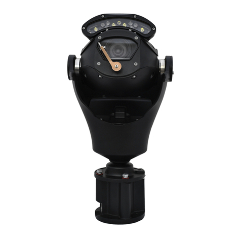
360 Vision Predator Ultra Instruction sheet

Predator
Installation / Configuration
Manual
Predator Installation Manual V10_1_29_00
Page 1 of 56
© 360 Vision Technology Ltd

Table of Contents
1 Safety and Precautions 3-4
2 Brackets &Housing Dimensional Drawing 5-10
3 Connections 11
4 Standalone Alarm card Setup 14
5 Predator Washer / Nozzle Bracket 18
6 Connections to Predator with HMA 19
7 Basic Twisted Pair/RS485 Data Wiring 23
8 Predator Protocol / Address setup 23
9 Predator OSD 24
10 Pin Number 25
11 OSD Operation / Navigation 26
12 Locating the Predator on your Network 32
13 Connecting to the Predator Hybrid 32
14 Live View 34
15 Live Video 34
16 Status 35
17 Settings 36
18 Video 36
19 Video Advanced 34
20 Advanced Features 39
21 Camera 41
22 Date / Time 43
23 Network 44
24 Interfaces 45
25 Add/ Edit Users 47
26 Maintenance 48
27 Browser 50
28 Network Settings Recovery 50
29 Special Presets 51
30 Important – Care of Painted Surfaces 51
31Storage and Handling 52
32 Warranty 52
33 PSU Enclosure 52
34.1080p Stream Resolutions & RTSP Links 52
35 White Balance and Fast Shutter options 53
36 Recording 54
37 Recording Browser 55
Predator Installation Manual V10_1_29_00
Page 2 of 56
© 360 Vision Technology Ltd

Photo-biological safety
Lighting options:
SIR110, SIR140WL, SIR160, 250SWL
The lighting options listed above fulfil the requirements for photo-biological safety
according to IEC/EN 62471 (risk group1).
Avoid prolonged eye exposure, do not stare at operating lamp.
Lighting options:
SIR200, SIR275, SIR250WL, SIR400, SIR550S, 400SWL, SIR100W200N
The lighting options listed above fulfil the requirements for photo-biological safety
according to IEC/EN 62471 (risk group2).
Avoid prolonged eye exposure, do not stare at operating lamp.
1 Safety and Pcautions
Predator Installation Manual V10_1_29_00
Page 3 of 56
© 360 Vision Technology Ltd

Safety and Pcautions
Predator Installation Manual V10_1_29_00
Page 4 of 56
© 360 Vision Technology Ltd

Predator Installation Manual V10_1_29_00
Page 5 of 56
© 360 Vision Technology Ltd

Predator Installation Manual V10_1_29_00
Page 6 of 56
© 360 Vision Technology Ltd

Dual View Dimentions & Predator Thermal (up to 35mm lens) with LED array and built in thermal encoder
Predator Installation Manual V10_1_29_00
Page 7 of 56
© 360 Vision Technology Ltd

Predator Installation Manual V10_1_29_00
Page 8 of 56
© 360 Vision Technology Ltd

2 Brackets & Dimensional Drawings
PMA Bracket
Predator Installation Manual V10_1_29_00
Page 9 of 56
© 360 Vision Technology Ltd

Wall Bracket
Corner Bracket
PMB Bracket
Predator Installation Manual V10_1_29_00
Page 10 of 56
© 360 Vision Technology Ltd

MAINS FUSE
PRED-PSU-SM
MAINS FUSE 3 = 2AF
OUTPUT FUSE
PRED-PSU-SM
FUSE 1 = 6.3AT
FUSE 2 = 1AT
FUSE 4 = N/A
Io Vo
Adj Adj
Use pre-made cable PRED-3M,
PRED-10m, PRED-25m or
PRED-40m to connect to the
Predator camera.
PRED-PSU-SM
255 x 180 x 100mm
Enclosure Dimensions
Analogue Version Wiring
To Analogue
Controller
30Vdc(+)
PINK
0Vdc(-)
GREEN
30Vdc(+)
GREY
0Vdc(-)
WHITE
30Vdc(+)
BROWN
0Vdc(-)BLACK
Coax Core
Coax Screen
RED
ORANGE
RS485 D+
RS485 D-
Coax Core (TC)
Coax Screen (TC)
This PSU is compatible with the following products: ANALOGUE PREDATOR NON-HMA
SAFETY: Isolate mains supply while installing.
FIXING: Securely fix the PSU with suitable fixings.
GLANDS: Face downwards, unused glands must be sealed.
ELECTRICAL CONNECTIONS: Connecting the mains power.
MAINS INPUT 100-240Vac
L=LIVE (BROWN) 100-240Vac 50/60Hz
E=EARTH (GREEN/YELLOW)
N=NEUTRAL (BLUE)
SAFETY: ENSURE MAINS INPUT AND EARTH CONNECTIONS ARE SECURELY CONNECTED AND STRAIN
RELIEVED.
FUSE PROTECTION: Mains input fuse 2AF.
360Vision Technology, 7 Seymour Court Manor Park, Runcorn, Cheshire, WA7 1SY, Tel +44 (0)1928 570000.
www.360visiontechnology.com
Model Number: PRED-PSU-SM-HMA
Serial Number: yymmndd-xxxx
Input Voltage: 100 – 240V AC 50/60Hz
Input Current: 2.1A
Output Voltage: 30V DC
Output Current: 6.2A
360Vision Technology, 7 Seymour Court Manor Park, Runcorn,
Cheshire, WA7 1SY, Tel +44 (0)1928 570000.
www.360visiontechnology.com
PRED-PSU-SM Safety and Installation Sheet
360
USE
3 Connections
Predator Installation Manual V10_1_29_00
Page 11 of 56
© 360 Vision Technology Ltd

Predator Installation Manual V10_1_29_00
Page 12 of 54
© 360 Vision Technology Ltd
SEE BELOW PRED-HYB-PSU-SM
Predator Installation Manual V10_1_29_00
Page 12 of 56
© 360 Vision Technology Ltd

This PSU is compatible with the following products: HD/IP PREDATOR WITH ALARMS
SAFETY: Isolate mains supply while installing.
FIXING: Securely fix the PSU with suitable fixings.
GLANDS: Face downwards, unused glands must be sealed.
ELECTRICAL CONNECTIONS: Connecting the mains power.
MAINS INPUT 100-240Vac
L=LIVE (BROWN) 100-240Vac 50/60Hz
E=EARTH (GREEN/YELLOW)
N=NEUTRAL (BLUE)
SAFETY: ENSURE MAINS INPUT AND EARTH CONNECTIONS ARE SECURELY CONNECTED AND STRAIN
RELIEVED.
FUSE PROTECTION: Mains input fuse 2AF.
360Vision Technology, 7 Seymour Court Manor Park, Runcorn, Cheshire, WA7 1SY, Tel +44 (0)1928 570000.
www.360visiontechnology.com
FUSES
PRED-XALARM-PSU-SM-HD
FUSE 1 = 6.3AT
FUSE 2 = 1AT
FUSE 3 = 2AF
FUSE 4 = N/A
MAINS input
100 - 240Vac
Io Vo
Adj Adj
ALARM INPUTS
CON1
(e.g. Connect A1 to COM
to activate Alarm 1)
ALARM RELAY OUTPUT
CON3 (Volts Free)
0.5A 125Vac max.
1A 24Vdc max
PRED-XALARM-PSU-SM-HD
Coax Core
Coax Screen
Use pre-made cable
PRED-3M, connect to
Predator.
NOTE - All wires in
composite cable must
be connected.
255 x 180 x 100mm
Enclosure Dimensions
30Vdc(+)PINK
0Vdc(-)GREEN
30Vdc(+)GREY
0Vdc(-)WHITE
30Vdc(+)BROWN
0Vdc(-)BLACK
Tx-
Rx-
Rx+
Tx+
RED
ORANGE
VIOLET
BLUE
Camera Network/
Ethernet connection
PRED-XALARM-PSU-SM-HD Safety and Installation Sheet
Model Number: PRED-XALARM -PSU-SM-HD
Serial Number: yymmndd-xxxx
Input Voltage: 100 – 240V AC 50/60Hz
Input Current: 2.1A
Output Voltage: 30V DC
Output Current: 6.2A
360Vision Technology, 7 Seymour Court Manor Park, Runcorn,
Cheshire, WA7 1SY, Tel +44 (0)1928 570000.
www.360visiontechnology.com
PRED-XALARM-PSU-SM-HD_v2
Predator Installation Manual V10_1_29_00
Page 13 of 56
© 360 Vision Technology Ltd

1 1
2 2
8 8
4.1 Standalone Alarmcard Setup
15
1
15
a Inp
4 Standalone Alarm card
Predator Installation Manual V10_1_29_00
Page 14 of 56
© 360 Vision Technology Ltd

Normally Closed Contacts (Un-used inputs must be connected to common)
RS485 Address Settings
Normally Open Contacts
Address 1 to 128 range
Predator Installation Manual V10_1_29_00
Page 15 of 56
© 360 Vision Technology Ltd

Predator Installation Manual V10_1_29_00
Page 16 of 56
© 360 Vision Technology Ltd

MAINS FUSE
PRED-PSU-SM-WA-HD
MAINS FUSE 3 = 2AF
OUTPUT FUSE
PRED-PSU-SM-WA-HD
FUSE 1 = 6.3AT
FUSE 2 = 1AT
FUSE 4 = 1AT
MAINS input
100 - 240Vac
Io Vo
Adj Adj
PRED-PSU-SM-WA-HD
Coax Screen
Coax Core
Use pre-made cable
PRED-3M, PRED-10m,
PRED-25m or PRED-40m
to connect to Predator.
255 x 180 x 100mm
Enclosure Dimensions
360
USE
30VdcPINK
0VdcGREEN
30VdcGREY
0VdcWHITE
30VdcBROWN
0VdcBLACK
Tx-
Rx-
Rx+
Tx+
RED
ORANGE
VIOLET
BLUE
Camera Network/
Ethernet connection
Model Number: PRED-PSU-SM-WA
Serial Number: yymmndd-xxxx
Input Voltage: 100 – 240V AC 50/60Hz
Input Current: 2.1A
Output Voltage: 30V DC
Output Current: 6.2A
360Vision Technology, 7 Seymour Court Manor Park, Runcorn,
Cheshire, WA7 1SY, Tel +44 (0)1928 570000.
www.360visiontechnology.com
PRED-PSU-SM-WA Safety and Installation Sheet
This PSU is compatible with the following products: HD/IP PREDATOR NON-HMA WITH WASHER
SAFETY: Isolate mains supply while installing.
FIXING: Securely fix the PSU with suitable fixings.
GLANDS: Face downwards, unused glands must be sealed.
ELECTRICAL CONNECTIONS: Connecting the mains power.
MAINS INPUT 100-240Vac
L=LIVE (BROWN) 100-240Vac 50/60Hz
E=EARTH (GREEN/YELLOW)
N=NEUTRAL (BLUE)
SAFETY: ENSURE MAINS INPUT AND EARTH CONNECTIONS ARE SECURELY CONNECTED AND STRAIN
RELIEVED.
FUSE PROTECTION: Mains input fuse 2AF.
360Vision Technology, 7 Seymour Court Manor Park, Runcorn, Cheshire, WA7 1SY, Tel +44 (0)1928 570000.
www.360visiontechnology.com
WASHER
Output
100 - 240Vac
PRED-PSU-SM-WA_V2
Predator Installation Manual V10_1_29_00
Page 17 of 56
© 360 Vision Technology Ltd

5 Predator
Washer/Nozzle Bracket
Nozzle bracket.
The Predator washer bracket kit includes the bracket, nozzle M8 plain metal washer, M8 lock washer and four
cable ties.
Nozzle Adjustment
The nozzle is set to produce a vertical water jet. The direction of the jet can be adjusted by rotating the nozzle
body in the bracket, or by using the screw-driver slot.
Fixing Bracket to Predator
Choose one of the four M8 Predator fixing bolt positions to be used to mount the nozzle bracket so that it does
not obscure an important view. E.g. directly above the horizontal bar of a wall bracket would be suitable.
Fit an M8 flat metal washer between the Predator base and the nozzle bracket so that the base of the bracket
is not crooked. Fit an M8 lock washer under the head of the bolt to reduce the risk of the bolt becoming loose
and the bracket moving. Ensure that the curved end of the bracket fixing plate is directed towards the Predator
pan shaft so that the vertical part of the bracket is the maximum distance from the rotating body.
Tube Connection
Suitable tube (not supplied) for connection to the nozzle is PVC with internal diameter 3mm and outside
diameter 6mm PVC.
The end of the tube is pushed over the ridged tube at the rear of the nozzle. Fit a cable tie around the joint
between the PVC tube and the rear of the nozzle to ensure that the tube cannot become detached.
The PVC tube should weave through the two slots in the bracket to provide strain relief. Cable ties can be used
to secure the tube so that it is clear of the Predator's rotating body. Take care that the cable ties do not cause
excessive restriction of the tube.
Water Jet direction (vertical)
Adjustable Nozzle
Tie
Tube
Nozzle Bracket located
Fit M8 Plain Washer Between Nozzle
Bracket and Predator Mounting
Base.
Predator Installation Manual V10_1_29_00
Page 18 of 56
© 360 Vision Technology Ltd

6 Connections to
Pr
e
da
to
r
with HMA
Predator Installation Manual V10_1_29_00
Page 19 of 56
© 360 Vision Technology Ltd

MAINS FUSE
PRED-PSU-SM-HMA
MAINS FUSE = 2AF
MAINS input
100 - 240Vac
Io Vo
Adj Adj
PRED-PSU-SM-HMA
30Vdc
0V
255 x 180 x 100mm
Enclosure Dimensions
PRED-PSU-SM-HMA_v3
This PSU is compatible with the following products: PREDATOR HMA
SAFETY: Isolate mains supply while installing.
FIXING: Securely fix the PSU with suitable fixings.
GLANDS: Face downwards, unused glands must be sealed.
ELECTRICAL CONNECTIONS: Connecting the mains power.
MAINS INPUT 100-240Vac
L=LIVE (BROWN) 100-240Vac 50/60Hz
E=EARTH (GREEN/YELLOW)
N=NEUTRAL (BLUE)
SAFETY: ENSURE MAINS INPUT AND EARTH CONNECTIONS ARE SECURELY CONNECTED AND STRAIN
RELIEVED.
FUSE PROTECTION: Mains input fuse 2AF.
Model Number: PRED-PSU-SM-HMA
Serial Number: yymmndd-xxxx
Input Voltage: 100 – 240V AC 50/60Hz
Input Current: 2.1A
Output Voltage: 30V DC
Output Current: 6.2A
360Vision Technology, 7 Seymour Court Manor Park,
Runcorn, Cheshire, WA7 1SY, Tel +44 (0)1928 570000.
www.360visiontechnology.com
L
E
N
PRED-PSU-SM-HMA Safety and Installation Sheet
360Vision Technology, 7 Seymour Court Manor Park, Runcorn, Cheshire, WA7 1SY, Tel +44 (0)1928 570000.
www.360visiontechnology.com
Predator Installation Manual V10_1_29_00
Page 20 of 56
© 360 Vision Technology Ltd
Other manuals for Predator Ultra
1
This manual suits for next models
1
Table of contents
Other 360 Vision Security Camera manuals
360 Vision
360 Vision Vision i Dome Instruction sheet
360 Vision
360 Vision Predator Radar Instruction sheet

360 Vision
360 Vision Illuminator HD Instruction sheet

360 Vision
360 Vision Invictus Hybrid Manual

360 Vision
360 Vision Eclipse HD Stainless Steel Instruction sheet

360 Vision
360 Vision PRED-3M Instruction sheet

360 Vision
360 Vision Predator Ultra Instruction sheet

360 Vision
360 Vision Visiondome-HD Instruction sheet
360 Vision
360 Vision Predator-Dualview Manual
360 Vision
360 Vision Visiondome-VR Instruction sheet