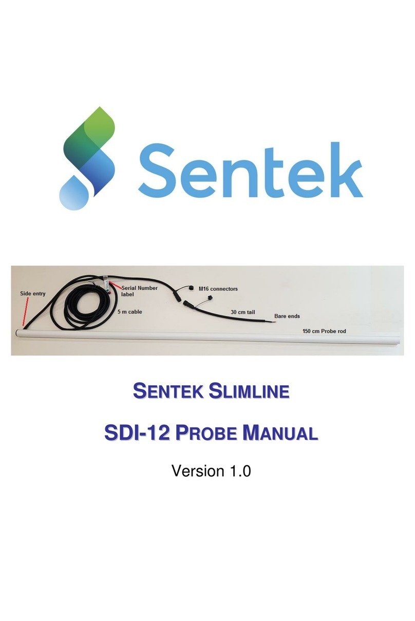
Sentek SDI-12 User manual

S
SE
EN
NT
TE
EK
K
D
DR
RI
IL
LL
L
&
&
D
DR
RO
OP
P
Probe Manual Version 1.1

Sentek Drill & Drop Probe Manual
Copyright © 2001 –2014 Sentek Pty Ltd All rights reserved Page i
All rights reserved. No part of this document may be reproduced, transcribed, translated into any language or
transmitted in any form electronic or mechanical for any purpose whatsoever without the prior written
consent of Sentek Pty Ltd. All intellectual and property rights remain with Sentek Pty Ltd.
All information presented is subject to change without notice.
2001-2014 Sentek Pty Ltd
Sentek™, Drill & Drop™, EnviroSCAN™ , EasyAG™, TriSCAN™, and IrriMAX™ are trademarks or
registered trademarks of Sentek Pty Ltd that may be registered in one or more jurisdictions.
Sentek Pty Ltd
A.C.N. 007 916 672
77 Magill Road
Stepney, South Australia 5069
Phone: +61 8 8366 1900
Facsimile: +61 8 8362 8400
Internet: http://www.sentek.com.au
Email: [email protected]
Drill & Drop Rev 1.1 (2014-08-28)

Sentek Drill & Drop Probe Manual
Copyright © 2001 –2014 Sentek Pty Ltd All rights reserved Page ii
Sentek - Statements of Compliance
FCC note of compliance and statement of liability
This equipment has been tested and found to comply with the limits for a Class B digital device,
pursuant to part 15 of the FCC rules. These limits are designed to provide reasonable protection against
harmful interference in a residential installation. This equipment generates, uses and can radiate radio
frequency energy and, if not installed and used in accordance with the instructions, may cause harmful
interference to radio communications. However, there is no guarantee that interference will not occur
in a particular installation. If this equipment does cause harmful interference to radio or television
reception, which can be determined by turning the equipment off and on, the user is encouraged to try
to correct the interference by one or more of the following measures:
Reorientation or relocation of the receiving antenna.
Connection of the equipment into an outlet on a circuit different from that to which the receiver
is connected.
Consultation with the dealer or an experienced radio/TV technician.
EMC approvals
The Drill & Drop system complies with the following specifications;
FCC Part 15 Subpart B
Radio Frequency Devices –Unintentional Radiators
CISPR 11:2010 Ed 5.1
Industrial Scientific and Medical (ISM) radio-frequency equipment –Electromagnetic
disturbance characteristics –Limits and methods of measurement
IEC 6132601:2012 Ed 2
Electrical equipment for measurement, control and laboratory use –EMC requirements. Part 1:
General requirements.
RoHS
EN 50581:2012
Technical documentation for the assessment of electrical and electronic products with respect to
the restriction of hazardous substances.
Marking
The above EMC approvals allow the product to be marked CE, C-tick and FCC.
Modifications
Any modifications to any part of the equipment or to any peripherals may void the EMC compliance of
the equipment.
Radio Interference
The probe is not to be operated in free air as it may cause interference to radio communication devices

Sentek Drill & Drop Probe Manual
Copyright © 2001 –2014 Sentek Pty Ltd All rights reserved Page iii
Table of Contents
Sentek - Statements of Compliance .....................................................................ii
FCC note of compliance and statement of liability ........................................................ii
EMC approvals ....................................................................................................................ii
RoHS .....................................................................................................................................ii
Marking ............................................................................................................................ii
Modifications...................................................................................................................ii
Radio Interference..........................................................................................................ii
The Drill & Drop Probe........................................................................................1
References.............................................................................................................................1
Interface box.........................................................................................................................1
Probe......................................................................................................................................2
Cables.....................................................................................................................................2
Sentek Probe Configuration Utility...................................................................................2
Setting the SDI-12 Address...........................................................................................3
About the SDI-12 Communication .............................................................................3
Installation and setup of the Drill & Drop probe ................................................ 4
Wiring the Probe Cable........................................................................................ 5
SDI-12 Probe........................................................................................................................5
Sentek MULTI and Modbus RS485 probes ....................................................................5
Sentek PLUS and Modbus RS232 probes........................................................................6
Sentek SOLO probe............................................................................................................7
Drill & Drop Technical Specifications ................................................................ 8
RS232/RS485 Interface specification...............................................................................8
SDI-12 Interface Specifications.........................................................................................8

Sentek Drill & Drop Probe Manual
Copyright © 2001 –2014 Sentek Pty Ltd All rights reserved Page 1
The Drill & Drop Probe
This manual should be used in combination with the appropriate Sentek Hardware manual for which
the probe is configured i.e. Sentek MULTI, Sentek PLUS, Sentek SDI-12 or RS232/485Modbus.
The Drill & Drop probe complements the Sentek EnviroSCAN probe and Sentek EasyAG probe. It
comes in two sensor configurations of 6 sensors or 12 sensors.
The probe consists of two components and associated cables:
References
Drill & Drop Installation Manual
Sentek Probe Configuration Utility
TriSCAN Agronomic User Manual
Sentek SDI-12 Series II Probe Interface Manual
RS232/485 MODBUS Series II Hardware Manual
Sentek MULTI Hardware Manual
Sentek PLUS Hardware Manual
Interface box
The Interface box contains a Sentek interface device preconfigured and normalised to match the probe
rod configuration and the communications option.

Sentek Drill & Drop Probe Manual
Copyright © 2001 –2014 Sentek Pty Ltd All rights reserved Page 2
There are five communication options for the encapsulated interface box:
Product
Interface
Modem
Firmware Version
Sentek PLUS
RS232
NextG, GPRS and
CDMA (Verizon, USA)
Plus-Multi 1.6.2 or
later
Sentek MULTI
RS485
NextG, GPRS and
CDMA (Verizon,USA )
Plus-Multi 1.6.2 or
later
Third party SDI-12 loggers
SDI-12
N/A
SDI-12 1.4.2 or later
Sentek SOLO
RS232
N/A
Solo 1.3.2 or later
MODBUS
RS232 or RS485
N/A
Modbus 1.4.1 or later
The Interface box has two non-removable cables (with non-removable cable glands)
It also has weather proof connector for the Drill & Drop Probe Programming Cable.
Probe
The sensors and cable are encapsulated inside the probe rod:
6 or 12 moisture sensors
6 or 12 moisture and salinity sensors
Every sensor has an associated temperature sensor
Sensors are spaced at 10cm intervals
Probe length 60 cm (24 inches) or 120 cm (48 inches)
The probe interface is preconfigured to start sensors at depth 5cm
Cables
Drill & Drop Probe Programming Cable (for Probe Configuration Utility), USB to Interface box
connector (optional)
Non-removable 1m cable with ends encapsulated in interface box and in probe rod
Cable encapsulated at interface box, supplied with appropriate Sentek connector or bare
wires,.Cable length nominally 5m (see section Wiring the Probe Cable),
Sentek Solo has its cable pre-wired into the Solo Head Unit.
Custom cable lengths may be available with a special order.
Sentek Probe Configuration Utility
Warning!
Probes are supplied pre-normalised. Modifying information stored in the Drill & Drop probe interface
may result in incorrect volumetric water content (mm/10cm) readings being reported to the controlling
device.
The Probe Configuration Utility (PConfig) is provided to configure probe interfaces with depth
location, normalization values (air and water counts) and calibration information for each sensor
installed on the probe. This information is stored in non-volatile memory, and is used to produce the
calculated value (value that has been processed via the interfaces calibration formula) from each sensor
on the probe.
It is not necessary to configure the sensors or normalise Drill & Drop probes as they are sold fully
preconfigured and normalised. An optional Drill & Drop Pconfig cable is available if required.

Sentek Drill & Drop Probe Manual
Copyright © 2001 –2014 Sentek Pty Ltd All rights reserved Page 3
The sampling interval, Web URL address etc. in the Interface box must be setup during commissioning
the probe.
See the Probe Configuration Utility manual or help for further information.
Setting the SDI-12 Address
Drill & Drop SDI-12 probes are preconfigured to SDI-12 address 0.
If multiple probes are on the one SDI-12 bus it will be necessary to use either your SDI-12 logger or
PConfig to change the SDI-12 address of the probe in the range "0" to "9", "A" to "Z" and "a" to "z".
About the SDI-12 Communication
See the Sentek SDI-12 Series II Probe Interface Manual for a description of SDI-12 communication to
a Sentek probe.

Sentek Drill & Drop Probe Manual
Copyright © 2001 –2014 Sentek Pty Ltd All rights reserved Page 4
Installation and setup of the Drill & Drop probe
Physical installation at the desired field location is described in the Drill & Drop Installation Manual.
See the appropriate Sentek PLUS, Sentek SOLO or Sentek MULTI hardware manual for full setup
description.
1. Plug the Interface to DTU cable into the probe connector on the DTU (or third part logger).
2. Plug the DTU front panel PConfig cable into your computer
For SDI-12 or Modbus: Plug the Drill & Drop PConfig cable to the Interface box and to your
Computer.
3. Open PConfig connection to the probe and set required parameters in the interface:
Note: It is not necessary to Auto-detect sensors, set depths or normalise sensors
Synchronise Interface clock to computer clock
Enter Upload URL
Sample interval (preconfigured to 15 minutes)
Sample upload count (preconfigured to 12, for upload every 3 hours)
Change network tab Initialisation setting if your SIM card is configured to use a PIN
Ensure you have a SIM card in the DTU modem
4. Verify the probe is operational by performing a Modem Test, expecting a last response of 040
Success.

Sentek Drill & Drop Probe Manual
Copyright © 2001 –2014 Sentek Pty Ltd All rights reserved Page 5
Wiring the Probe Cable
Most Drill & Drop probes are pre-configured with the appropriate firmware and cable plug for Sentek
PLUS, Sentek SOLO, Sentek MULTI.
For probes that need to be wired, there are three cable configurations. The "Type" label on the Drill &
Drop Interface box identifies which type of probe is relevant.
Caution:
Damage to the Drill & Drop cable may result in moisture entering the cable, resulting in corrosion and
device failure.
SDI-12 Probe
An SDI-12 probe require connection to a third-party logger, consequently no cable connector can be
specified.
SDI-12 Cable
+Vin
0V
DATA
N/C
N/C
5-wire cable
Red
Green
White
Blue
Yellow
Sentek MULTI and Modbus RS485 probes
The Sentek MULTI DTU has a built in connector which uses a four pin "Buccaneer" plug. If required
the probe end connector can be ordered as Sentek Part number:
04086 Sentek MULTI, Probe Cable Connector
For detailed wiring steps, see section Sentek MULTI Probe Cable Connector in the Sentek MULTI Hardware
Manual.
A Modbus RS485 probe require connection to a third-party logger, consequently no cable connector
can be specified.
485 Cable
+Vin
0V
A
B
N/C
5-wire cable
Red
Green
Blue
White
Yellow

Sentek Drill & Drop Probe Manual
Copyright © 2001 –2014 Sentek Pty Ltd All rights reserved Page 6
MULTI Connector Pin
1
2
3
4
Sentek PLUS and Modbus RS232 probes
The Sentek PLUS DTU has a connector which uses a seven pin "Buccaneer" plug. If required this
connector can be ordered as Sentek Part number:
61249 Water tight connector, Sentek PLUS, Probe end
For detailed wiring steps, see section C. Install EnviroSCAN Flat Cap probe (common to all probe types)
in the Sentek PLUS Hardware Manual.
A Modbus RS232 probe require connection to a third-party logger, consequently no cable connector
can be specified.
232 Cable
+Vin
SWCH
In
SWCH
out
0V
TX
RX
RTS
CTS
N/C
9 wire cable
Red
Orange
Brown
Black
Blue
Purple
Green
Yellow
Grey
Plus Connector
pin
1
1 with
Red
2
3
4
5
6
Center
No pin
If the Sentek PLUS DTU does not have a cable with Buccaneer connector, the Drill & Drop probe
cable can be wired directly into connector X2 on the PLUS solar charger board. See section Sentek
PLUS DTU in the Sentek PLUS Hardware Manual.

Sentek Drill & Drop Probe Manual
Copyright © 2001 –2014 Sentek Pty Ltd All rights reserved Page 7
Sentek SOLO probe
A Drill & Drop probe is either supplied:
Pre-assembled in a Sentek SOLO system, with the cable already wired into the SOLO Head
unit.
With a cable that has a bare end. This end must be joined to the existing SOLO Head Unit
cable. This is done using quick connector (PN: 61248) on both Drill & Drop and SOLO Head
Unit cables.
Figure 1: 61248 - Water tight connector Kit, Sentek SOLO or PLUS
Instructions on how to install these connectors can be found in the Sentek PLUS hardware manual.
Wiring order for the SOLO is identical to PLUS.
Note:
Sentek recommends keeping total cable distance between the probe interface and Sentek SOLO Head
unit to 5m or less.

Sentek Drill & Drop Probe Manual
Copyright © 2001 –2014 Sentek Pty Ltd All rights reserved Page 8
Drill & Drop Technical Specifications
All sensors and electronics are encapsulated within the probe rod. The interface box is also
encapsulated and its cable to the probe rod cannot be disconnected.
Sensors are measured starting from the bottom sensor (6 or 12)
Moisture Sensor Resolution: 1:10000
Moisture Sensor Precision: ±0.03% vol.
TriSCAN Sensor Resolution: 1:6000
Temperature Sensor Accuracy: ±2 Deg. C @ 25 Deg C.
Temperature Sensor Resolution: 0.3 Deg C.
Temperature range (operating): -20 Deg C to +60 Deg C.
RS232/RS485 Interface specification
Voltage Supply (+Vin): Modbus and Plus 4 to 15 Volts DC, Nominal 12V
SOLO 4.5 to 6.5 Volt DC, Nominal 6V
MULTI 6.5 to 15 Volt DC, nominal 12 Volt
Current consumption (RS232/RS485): 400µA standby @ 12 V DC
9mA Active @ 12 V DC
25mA @ 12 V DC** Average current over sensor sampling period.
800uA standby @ 6 V DC
16mA Active @ 6 V DC
45mA @ 6 V DC ** Average current over sensor sampling period.
Current is measure at the interface, production version 2.4 manufactured in 2013.
Time to sample 12 sensors: 1.8 seconds for Moisture and Temperature
(approx. 150ms per sensor **)
2.2 seconds for Moisture, TriSCAN and Temperature
(approx. 180ms per sensor **)
Time to sample 6 sensors: 1.1 seconds for Moisture and Temperature
(approx. 215ms per sensor **)
1.3 seconds for Moisture, TriSCAN and Temperature
(approx. 180ms per sensor **)
** Note: Sensor measurement time is approximate and an average of the total time to measure all
sensor types at a single depth.
TTL Interface baud rate: 1200, 2400, 9600 (default), 19200 and 38400 bits per second
SDI-12 Interface Specifications
SDI-12 Protocol : Version 1.2
Time to sample M!, M2!, M4!, C!, C1! commands:

Sentek Drill & Drop Probe Manual
Copyright © 2001 –2014 Sentek Pty Ltd All rights reserved Page 9
1.8 seconds for 12 Sensor Moisture and Temperature.
2.2 seconds for 12 Sensor Moisture, TriSCAN and Temperature.
1.1 seconds for 6 Sensor Moisture and Temperature.
1.3 seconds for 6 Sensor Moisture, TriSCAN and Temperature.
Time to sample M1!, M3! & M5! commands:
0.8 seconds for 12 Sensor Moisture and Temperature.
Voltage Supply (+Vin): 5 to 15 Volts DC
Current consumption (SDI-12): Idle and Sleep currents are as per SDI-12 specification.
Mode:
Current consumption
SDI-12 Sleep
SDI-12 Idle

Sentek Drill & Drop Probe Manual
Copyright © 2001 –2014 Sentek Pty Ltd All rights reserved Page 10
Mode:
Current consumption
SDI-12 Sampling
Other manuals for SDI-12
1
Table of contents
Other Sentek Analytical Instrument manuals
Popular Analytical Instrument manuals by other brands
DNT
DNT Snakoo user manual
Powerfix Profi
Powerfix Profi PEK 2.4 B1 User manual and service information
Agilent Technologies
Agilent Technologies E4440A Getting started guide

Teledyne
Teledyne 3000TA-XL-EU operating instructions
Siemens
Siemens SIPROCESS GA700 quick start
Aethra
Aethra D2010 Technical specifications
