manuals.online logo
Brands
  1. Home
  2. •
  3. Brands
  4. •
  5. TFA
  6. •
  7. Thermometer
  8. •
  9. TFA MALIBU WIRELESS POOL THERMOMETER User manual

TFA MALIBU WIRELESS POOL THERMOMETER User manual

4
+ button
MIN/MAX / RESET
button
SET button
MALIBU
WIRELESS POOL THERMOMETER
Instructions Manual
Cat. No. 30.3053.IT
Thank you for choos ng th s adv ce from TFA.
BEFORE YOU USE IT
Please be sure to read the instruction anual carefully.
Th s nformat on w ll help you to fam l ar se yourself w th your new
dev ce, learn all of ts funct ons and parts, f nd out mportant deta ls
about ts f rst use and how to operate t, and get adv ce n the event
of faults.
Follow ng the nstruct on manual for use w ll prevent damage to the
dev ce and loss of your statutory r ghts ar s ng from defects due to
ncorrect use.
We shall not be liable for any da age occurring as a result of
not following these instructions. Likewise, we take no
responsibility for any incorrect readings and for any
consequences which ay result fro the .
Please look after this anual for future reference.
Please take particular note of the safety advice!
SCOPE OF SUPPLY:
• Temperature stat on (bas c stat on)
• Outdoor transm tter
• Pool sensor
• Instruct on manual
FIELD OF OPERATION AND ALL THE BENEFITS OF
YOUR NEW INSTRUMENT AT A GLANCE:
• For pool and pond
• Water temperature w reless v a pool sensor w th 100 mm
measur ng depth
• Outdoor temperature w reless v a outdoor transm tter
• Transm ss on range up to 100 m (free f eld)
• Ind cat on of ndoor temperature and hum d ty
• Max mum and m n mum values
• Dew po nt
• Rad o controlled clock
• Very s mple nstallat on, no cables requ red
FOR YOUR SAFETY:
• The product s exclus vely ntended for the f eld of appl cat on
descr bed above. The product should only be used as
descr bed w th n these nstruct ons.
• Unauthor sed repa rs, mod f cat ons or changes to the product
are proh b ted.
• The product s not to be used for med cal purpose or for publ c
nformat on, but s ntended solely for home use.
Caution!
Risk of injury:
• Keep the nstruments and the batter es out of reach of
ch ldren.
• Batter es must not be thrown nto the f re, short-c rcu ted,
taken apart or recharged. R sk of explos on!
• Batter es conta n harmful ac ds. Low batter es should be
changed as soon as poss ble to prevent damage caused by a
leak ng battery. Never use a comb nat on of old and new
batter es together or batter es of d fferent types. Wear
chem cal-res stant protect ve gloves and glasses when
handl ng leaked batter es.
! I portant infor ation on product safety!
• Do not expose the nstrument to extreme temperatures,
v brat on or shock.
• The outdoor transm tter s protected aga nst splash water, but
s not watert ght. Choose a shady and dry pos t on for the
outdoor transm tter.
• When water freezes remove the pool sensor.
ELEMENTS
The te perature station
The outdoor trans itter
• Remote transm ss on of outdoor
temperature to temperature stat on by 868
MHz s gnal
• Wall mount ng case
• Mount ng at a sheltered place. Avo d
d rect ra n and sunsh ne
The pool sensor
• Remote transm ss on of water temperature n pool or pond to
temperature stat on by 868 MHz s gnal
• Waterproof case
HOW TO INSTALL AND REPLACE BATTERIES IN THE
OUTDOOR TRANSMITTER
The outdoor transm tter uses 2 x AAA, IEC LR3,
1.5V batter es. To nstall and replace the
batter es, please follow the steps below:
1. Sl de the battery cover downwards and
remove t.
2. Insert the batter es, observ ng the correct
polar ty (see mark ng).
3. Replace the battery cover.
HOW TO INSTALL AND REPLACE BATTERIES IN THE
POOL SENSOR
The pool sensor uses 2 x AA, IEC LR6, 1.5V batter es. To nstall and
replace the batter es, please follow the steps below:
1. Hold the body of the pool sensor and unlock the upper part by
turn ng t counter clockw se and separate t carefully from the
body.
2. Insert batter es observ ng the correct polar ty (see mark ng).
3. Screw the two parts together aga n. Ensure that the cover s
flat and suff c ently t ght secured (mark ngs should
correspond). Th s w ll prevent water from enter ng the battery
compartment and subsequently damage the un t.
HOW TO INSTALL AND REPLACE BATTERIES IN THE
TEMPERATURE STATION
The temperature stat on uses 2 x
AAA, IEC LR3, 1.5V batter es. To
nstall and replace the batter es,
please follow the steps below:
1. Open the battery compartment
by push ng the battery cover
upwards w th your thumb.
Insert batter es observ ng the
correct polar ty (see mark ng).
2. Replace compartment cover.
SETTING UP
1. F rst, nsert the batter es n the outdoor transm tter (see “To
install and replace batteries in the te perature
trans itter” above).
2. Then, nsert the batter es n the pool sensor (see “To install
and replace batteries in the pool sensor” above)
3. W th n 15 seconds of power ng up the outdoor transm tter and
pool sensor, nsert the batter es n the temperature stat on
(see “To install and replace batteries in the te perature
station” above). Once the batter es are n place, all segments
of the LCD w ll l ght up br efly. Follow ng the ndoor
temperature/hum d ty and the t me as 00:00 w ll be d splayed.
If th s nformat on s not d splayed on the LCD after 60
seconds, remove the batter es and wa t for at least 60
seconds before re nsert ng them. Once the ndoor data s
d splayed user may proceed to the next step.
4. After the batter es are nserted, the temperature stat on w ll
start rece v ng data s gnal from the outdoor transm tter and
pool sensor. The outdoor temperature data should then be
d splayed on the temperature stat on. If th s does not happen
after 5 m nutes, the batter es w ll need to be removed from all
un ts and reset from step 1.
5. In order to ensure suff c ent 868 MHz transm ss on however,
the d stance between the temperature stat on and the outdoor
transm tter should not be more than 100 meters and 25
meters to the pool sensor ( n water). (see notes on
“Positioning” and “868 MHz Reception”).
Note:
In the event of chang ng batter es of the un ts, ensure the
batter es do not spr ng free from the contacts. Always wa t at
least 1 m nute after remov ng the batter es before re nsert ng,
otherw se start up and transm ss on problems may occur.
6. Once the outdoor data recept on per od s completed, the DCF
tower con n the clock d splay w ll start flash ng n the upper
left corner. Th s nd cates that the clock has detected that
there s a rad o s gnal present and s try ng to rece ve t. When
the t me code s rece ved, the DCF tower becomes
permanently l t and the t me w ll be d splayed.
RADIO-CONTROLLED TIME RECEPTION
The t me base for the rad o controlled t me s a Ces um Atom c Clock
operated by the Phys kal sch Techn sche Bundesanstalt
Braunschwe g. It has a t me dev at on of less than one second n one
m ll on years. The t me s coded and transm tted from Ma nfl ngen
near Frankfurt v a frequency s gnal DCF-77 (77.5 kHz) and has a
transm tt ng range of approx mately 1,500 km. Your rad o-controlled
clock rece ves th s s gnal and converts t to show the prec se t me.
‘Changeover from summer t me or w nter t me s automat cally.
The qual ty of the recept on depends greatly on the geograph c
locat on. In normal cases, there should be no recept on problems
w th n a 1.500 km rad us of Frankfurt.
DCF recept on s done tw ce da ly at 02:00 and 03:00 am. If the
recept on s not successful at 03:00 am, then the next recept on takes
place the next hour and so on unt l 06:00am, or unt l the recept on s
successful. If the recept on s not successful at 06:00 am, then the
next attempt w ll take place the next day at 02:00 am.
Please take note of the follow ng:
• The recommended d stance to any nterfer ng sources l ke
computer mon tors or TV sets s a m n mum of 1.5 - 2 meters.
• W th n Ferro-concrete rooms (basements, superstructures),
the rece ved s gnal s naturally weakened. In extreme cases,
please place the un t close to a w ndow and/ or po nt ts front
or back towards the Frankfurt transm tter.
• Dur ng n ghtt me, the atmospher c d sturbances are usually
less severe and recept on s poss ble n most cases. A s ngle
da ly recept on s adequate to keep the accuracy dev at on
under 1 second.
FUNCTION BUTTONS:
Te perature station:
The dev ce has 3 easy to use funct on buttons: 1 button on the front,
and 2 buttons on the back
LCD SCREEN
The LCD screen s spl t nto 4 sect ons d splay ng the nformat on for
t me, ndoor temperature and hum d ty, outdoor temperature and pool
temperature.
* When the s gnal s successfully rece ved by the temperature
stat on, the outdoor recept on con w ll be sw tched on. (If not
successful, the con w ll not be shown on LCD). The user can then
eas ly see whether the last recept on was successful ( con on) or not
( con off). On the other hand, the short bl nk ng of the con shows that
a recept on s currently tak ng place.
MANUAL SETTINGS
• T me zone sett ng
• T me recept on ON/OFF sett ng
• 12/24-hour sett ng
• Manual t me sett ng
• °C/°F temperature sett ng
• Factory reset sett ng (FAC)
Press and hold the SET button for about 3 seconds to enter the
sett ng mode:
TIME ZONE SETTING
The t me zone default s 0h. To set a d fferent t me zone:
1. The value of the actual set t me zone w ll be flash ng.
Foldable
stand
LCD
d splay
Funct on
button
Hang ng
hole
Battery
cover
T me
Indoor relat ve
hum d ty %
Outdoor recept on s gnal (pool sensor)*
Indoor
temperature/
dewpo nt n
°C or °F
Outdoor
temperature
n °C or °F
DCF
Tower con
(for t me
recept on)
Low battery
nd cator
(temperature
stat on)
Low battery
nd cator (pool
sensor)
Low battery
nd cator
(temperature
transm tter)
Outdoor
recept on
s gnal
(transm tter)*
Pool
temperature
n °C or °F
Funct on
buttons
T me Zone (flash ng)
5
Indoor relat ve
hum d ty %
Indoor relat ve
hum d ty %
2. Us ng the + button, set the t me zone. The range runs from –
2h to +5h n consecut ve 1 hour ntervals.
3. Conf rm w th the SET button and enter the “Ti e reception
ON/OFF setting”.
TIME RECEPTION ON/OFF SETTING
In areas where no DCF-77 t me s poss ble, you also have the
poss b l ty to deact vate the DCF recept on manually (OFF). The
clock w ll then work as a normal quartz clock. (Default sett ng s ON).
1. The symbol “ON” w ll be flash ng on the LCD.
2. Use the + button to deact vate (OFF) the t me recept on
funct on.
3. Conf rm w th the SET button and enter the “12/24-Hour
Display setting”.
Note:
If the ti e reception function is deactivated (OFF) anually, the
clock will not atte pt any reception of the radio-controlled ti e
(DCF ti e) as long as the ti e reception OFF function will be
activated (ON) again. If the ti e reception is deactivated (OFF)
the DCF sy bol disappears.
12/24 HOUR TIME DISPLAY SETTING
1. “24h” w ll be flash ng.
2. Press the + button to select the “12h” or “24h” d splay mode.
3. Conf rm w th the SET button and to enter the “Manual Ti e
setting”.
MANUAL TIME SETTING
In case the dev ce s not able to attempt the rad o-controlled t me
(d sturbances, transm tt ng d stance, etc.), the t me can be manually
set. The clock w ll then work as a normal quartz clock.
To set the clock:
1. The hour d g ts w ll be flash ng on the d splay.
2. Use the + button to adjust the hours.
3. Press the SET button to go to the m nute sett ng.
4. Use the + button to adjust the m nutes. Press and hold the
button n the sett ng mode for fast runn ng.
5. Conf rm w th the SET button and enter the “ºC/ºF te perature
unit setting”.
Note:
By a successfully recept on of the DCF s gnal and f the DCF
recept on s act vated (ON), the manually set t me w ll be overwr tten.
Dur ng the recept on the DCF symbol w ll be flash ng. If the recept on
s not successful rece ved, the DCF symbol d sappear. The next
attempt w ll st ll be held.
°C/°F TEMPERATURE SETTING:
The default temperature s set to °C (degree Cels us). To select °F
(degree Fahrenhe t):
1. Dur ng “ºC” w ll be flash ng, use the + button to toggle between
“ºC” and “ºF”.
2. Once the des red temperature un t has been chosen, conf rm
w th the SET button and enter the “Factory setting” or press
the MAX/MIN / RESET button to ex t the manual sett ng mode.
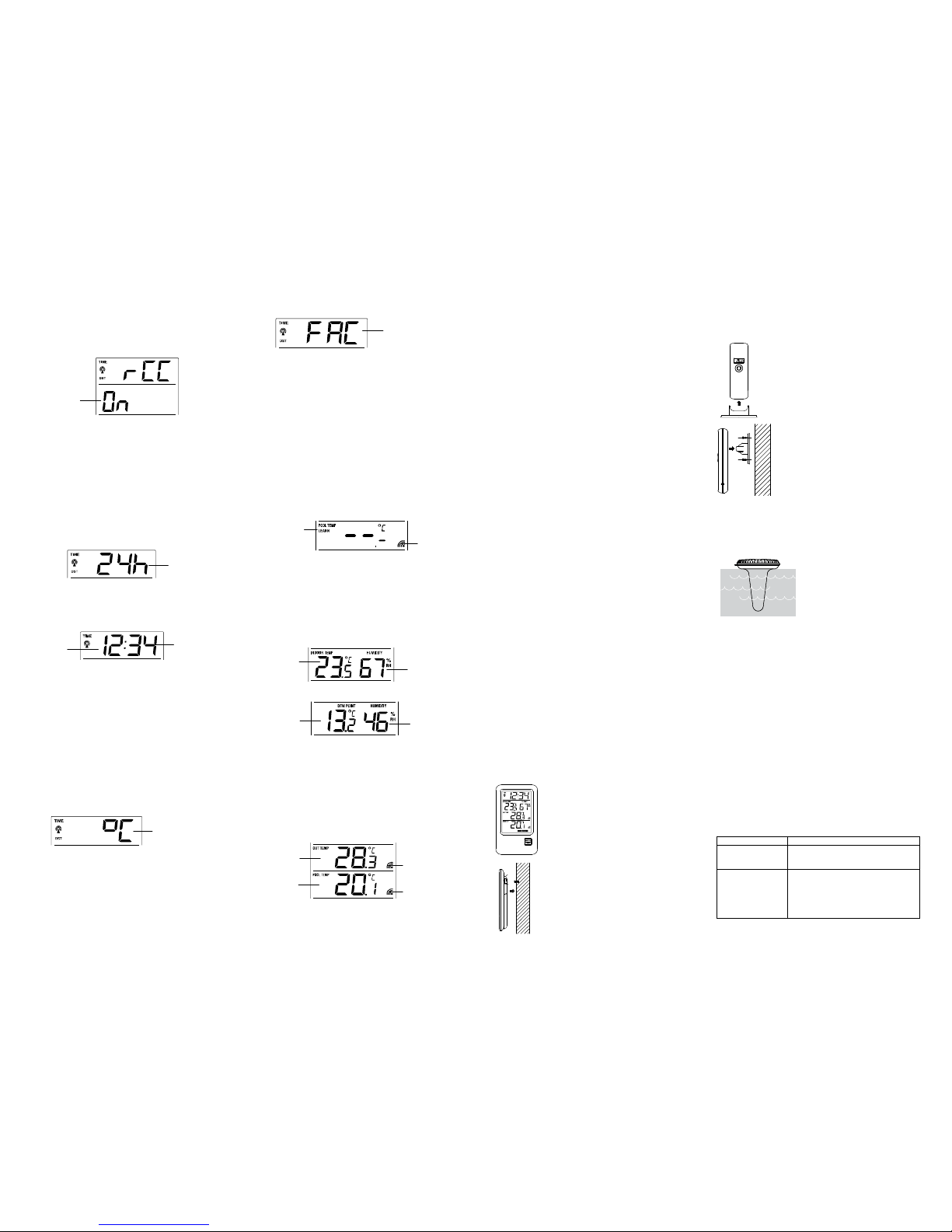
FACTORY RESET (FAC)
To reset the temperature stat on to the factory sett ngs:
1. Press and hold the + button for about 3 seconds to reset the
manual sett ngs to factory sett ngs.
2. Once the factory sett ng s done, all segments of the LCD w ll
l ght up br efly, then the t me, ndoor temperature and hum d ty
w ll be d splayed.
I portant:
• Dur ng factory sett ng, all s gnals from the transm tters are lost.
In order to rece ve the transm ss on s gnals from the
transm tters, please refer to “Setting up” above to set the
n t al recept on s gnal aga n.
TO EXIT THE MANUAL SETTING MODE
To ex t the manual sett ng mode anyt me dur ng the manual sett ng,
press the MAX/MIN / RESET button.
OUTDOOR TRANSMITTER AND POOL SENSOR
SEARCH MODE
If the transm tters are lost due to d sturbances, nterferences,
transm tt ng d stance, etc., a manual transm tter search can be
started.
1. Press the + button to select the transm tter.
2. “LEARN” appears n the d splay of the selected transm tter.
3. Press the SET button to start the search.
4. The recept on symbol w ll be flash ng.
5. As soon as the transm tter s found, the temperature appears
and the recept on symbol stays n the d splay.
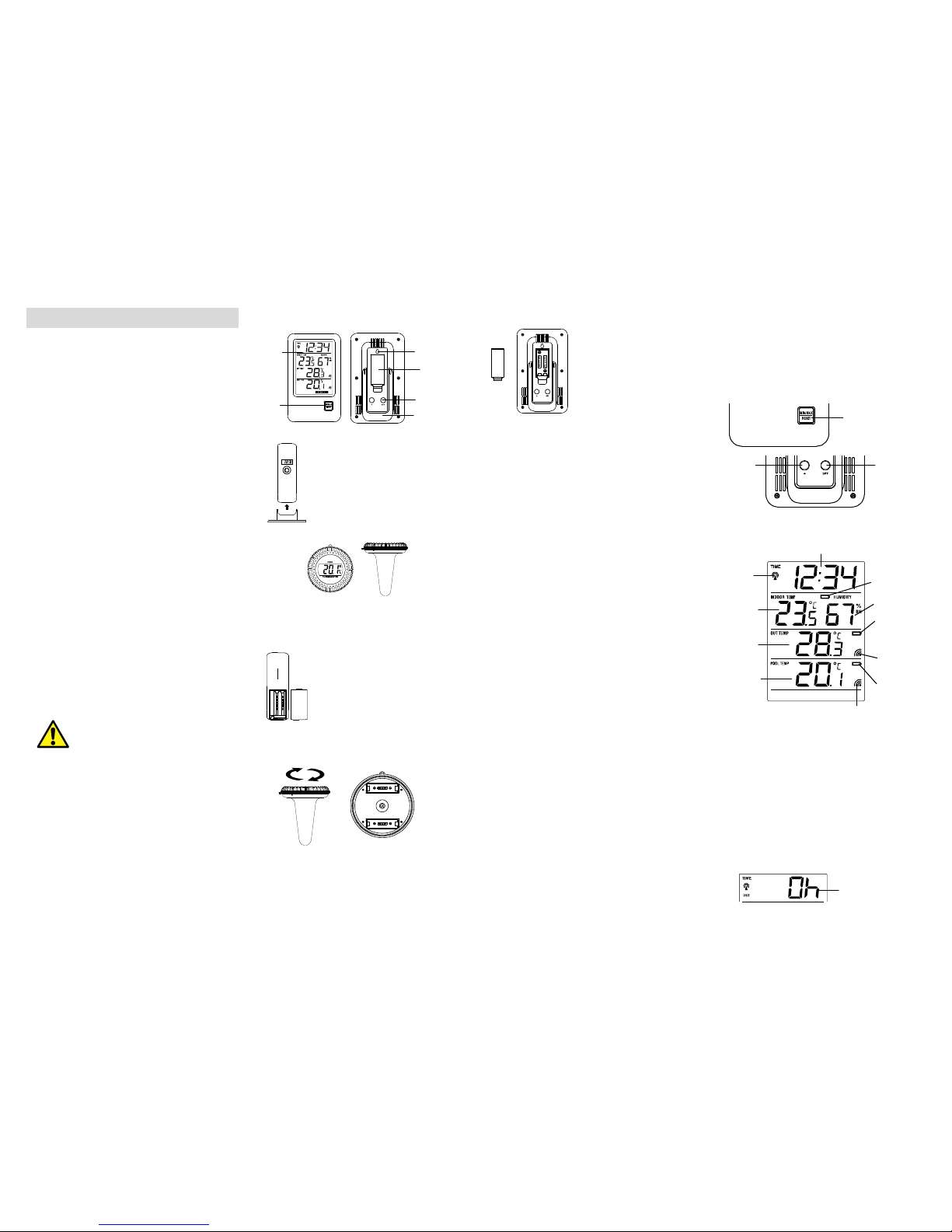
INDOOR TEMPERATURE / HUMIDITY AND DEW POINT
DATA
The ndoor temperature and hum d ty are detected automat cally and
d splayed on the second sect on of the LCD.
To d splay the dew po nt temperature, press the MAX/MIN / RESET
button 3 t mes.
DEW POINT appears n the d splay.
The dev ce w ll automat cally qu t the dew po nt mode f no button s
pressed for a lengthy per od (30 seconds) or press the MAX/MIN /
RESET button aga n to return to the actual d splay.
Note:
The dew po nt value s based on calculat on of the ndoor
temperature and hum d ty data.
OUTDOOR TEMPERATURE AND POOL
TEMPERATURE
The last two LCD sect on shows the outdoor temperature, pool
temperature and recept on s gnals.
TOGGLING AND RESETTING THE MIN/MAX DATA
TO VIEW THE MIN/MAX DATA AND DEW POINT
1. Press the MAX/MIN / RESET button the ndoor temperature
and hum d ty and the outdoor temperature and pool
temperature (MIN) appear.
2. Press the MAX/MIN / RESET button aga n the max mum
ndoor temperature and hum d ty and the outdoor temperature
and pool temperature (MAX) appear.
3. Press the button MAX/MIN / RESET aga n the dew po nt
appears (DEW-POINT).
4. The nstrument w ll automat cally qu t the MAX/MIN mode f no
button s pressed for a lengthy per od (30 seconds) or press
the MAX/MIN / RESET button aga n to return to the actual
d splay.
TO RESET THE MIN/MAX DATA
Press and hold MAX/MIN / RESET button for 3 seconds to reset
all the ndoor, outdoor and pool values to current values at the
same t me.
TRANSMITTERS
The outdoor data are measured and transm tted every 10 seconds.
The range of the transm tter s may be affected by the outdoor
temperature. At cold temperatures the transm tt ng d stance may be
decreased. Please bear th s n m nd when plac ng the transm tters.
868 MHz RECEPTION:
If the outdoor data are not be ng rece ved w th n three m nutes after
sett ng up (or outdoor d splay always show “- -. -” n the outdoor
sect ons of the temperature stat on dur ng normal operat on), please
check the follow ng po nts:
1. The d stance of the temperature stat on or transm tters should
be at least 2 meters away from any nterfer ng sources such
as computer mon tors or TV sets.
2. Avo d plac ng the transm tters onto or n the mmed ate
prox m ty of metal w ndow frames.
3. Us ng other electr cal products such as headphones or
speakers operat ng on the 868MHz-s gnal frequency may
prevent correct s gnal transm ss on or recept on. Ne ghbors
us ng electr cal dev ces operat ng on the 868MHz-s gnal
frequency can also cause nterference.
Note:
When the 868MHz s gnal s rece ved correctly, do not re-open the
battery cover of e ther the transm tter or temperature stat on, as the
batter es may spr ng free from the contacts and force a false reset.
Should th s happen acc dentally then reset all un ts (see “Setting up”
above) otherw se transm ss on problems may occur.
The transm ss on range s around 100 meters from the temperature
stat on to the outdoor transm tter ( n open space) and 25 meters to
the pool sensor ( n water). However, th s depends on the surround ng
env ronment and nterference levels. If no recept on s poss ble
desp te the observat on of these factors, all system un ts have to be
reset (see “Setting up” above).
POSITIONING THE TEMPERATURE STATION
The temperature stat on comes attached w th a fold ng stand, wh ch
prov des the opt on of table stand ng or wall mount ng the un t. Before
wall mount ng, please check that the outdoor temperature can be
rece ved from the des red locat ons.
Foldout table stand:
The foldout table stand leg s located on the
backs de. Pull the stand out from the bottom
center edge of the temperature stat on, below
the battery compartment. Once the foldout table
stand s extended, place the temperature stat on
n an appropr ate locat on.
To wall ount:
1. F x a screw (not suppl ed) nto the des red
wall, leav ng the head extended out by
about 5mm.
2. Place the temperature stat on onto the
screw, us ng the hang ng hole on the
backs de. Gently pull the temperature stat on down to lock the
screw nto place.
POSITIONING THE OUTDOOR TRANSMITTER
Mount the transm tter at a sheltered place. Avo d
d rect ra n and sunsh ne.
The outdoor transm tter s suppl ed w th a holder
that may be attached to a wall w th the two screws
suppl ed. The outdoor transm tter can also be
pos t on on a flat surface by secur ng the stand to
the bottom to the outdoor transm tter.
To wall ount:
1. Secure the bracket onto a des red wall
us ng the screws and plast c anchors.
2. Cl p the outdoor transm tter onto the
bracket.
Note:
Before permanently f x ng the outdoor
transm tter wall base, place all un ts n the
des red locat ons to check that the outdoor
temperature read ngs are rece vable. In event that the s gnal s not
rece ved, relocate the remote outdoor transm tter or move them
sl ghtly as th s may help the s gnal recept on.
POSITIONING THE POOL SENSOR
Place the pool sensor n any pool or pond to detect the water
temperature.
Note:
In event that the s gnal s not rece ved,
relocate the remote pool sensor or
move t sl ghtly as th s may help the
s gnal recept on.
CARE AND MAINTENANCE
• Clean the nstrument and the transm tters w th a soft damp
cloth. Do not use solvents or scour ng agents. Protect from
mo sture.
• Remove the batter es f you do not use the product for a
lengthy per od.
BATTERY REPLACEMENT
• Replace the batter es of the temperature stat on when the
battery symbol appears n the ndoor values d splay.
• Replace the batter es of the outdoor transm tter when the
battery symbol appears n the outdoor temperature d splay of
the temperature stat on and/or n the d splay of the outdoor
transm tter.
• Replace the batter es of the pool sensor when the battery
symbol appears n the pool temperature d splay of the
temperature stat on and/or n the d splay of the pool sensor.
Please note:
When the batter es are changed, the contact between outdoor
transm tter, pool sensor and bas c stat on must be restored –
so always nsert new batter es nto the three dev ces or start a
manual transm tter search.
• The manuals sett ngs w ll rema n unchanged.
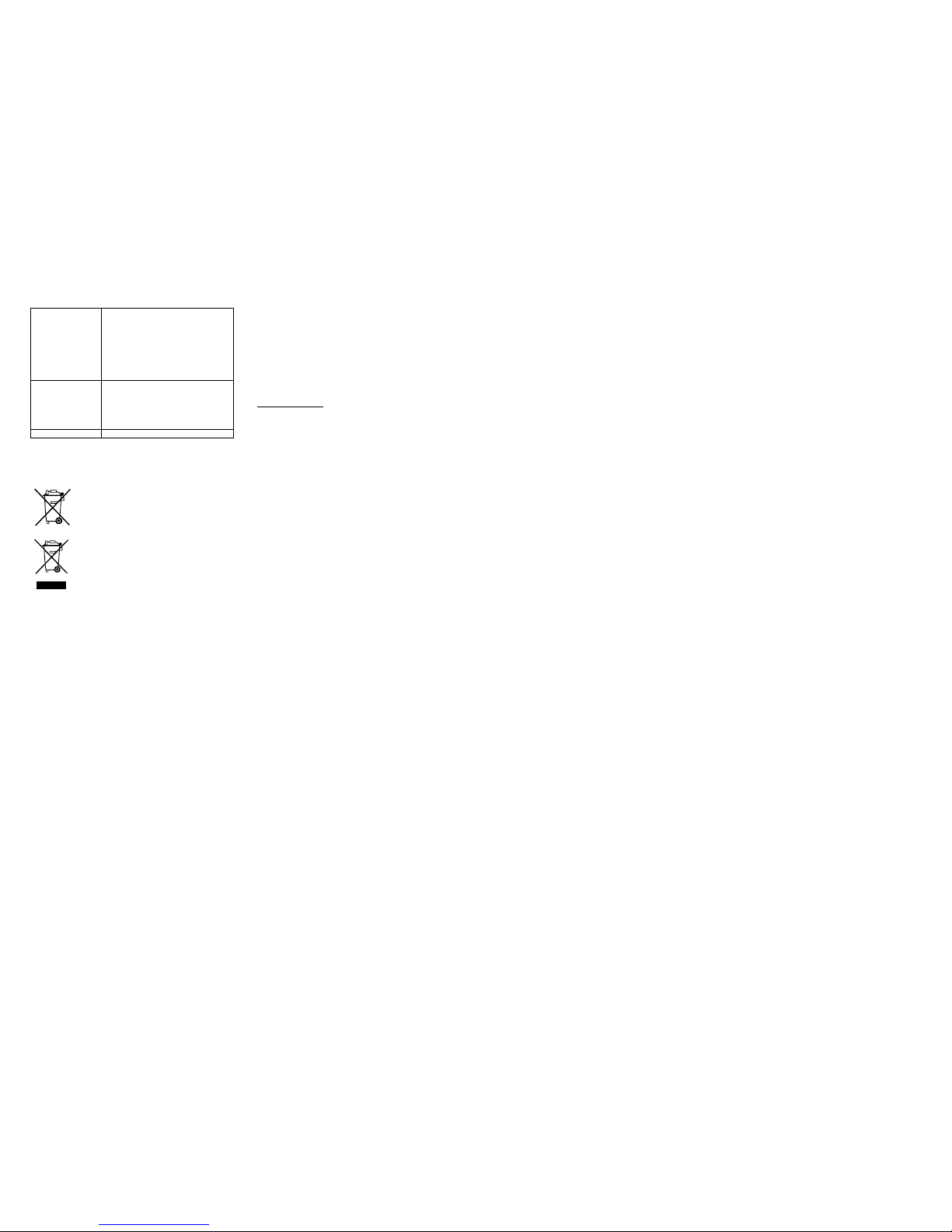
MALFUNCTION
Proble s Troubleshooting
No nd cat on on
the temperature
stat on
• Ensure batter es polar ty are correct
• Change batter es
No transm tter
recept on
D splay "---"
• Start a manual transm tter search
• Check batter es of external
transm tters (do not use
rechargeable batter es!)
• Restart the transm tters and
temperature stat on as per the
Temperature
transm tter
recept on
s gnal
Outdoor
temperature
n °C or °F
Indoor
temperature
n °C/°F
Dew po nt
temperature
n °C/°F
M nutes
(flash ng)
Hours
(flash ng)
Flash ng
Flash ng
Flash ng
Flash ng
Pool
temperature
n °C or °F
Pool sensor
recept on
s gnal
“LEARN” con
Recept on
s gnal flash ng
6
manual
• Choose another place for the
transm tters and/or the temperature
stat on
• Reduce the d stance between the
transm tters and the temperature
stat on
• Check f there s any source of
nterference
No DCF recept on • T me recept on sett ng “ON”
• Choose another place for the
temperature stat on
• Manual t me sett ng
• Wa t for attempted recept on dur ng
the n ght
Incorrect d splay • Change batter es
WASTE DISPOSAL
Th s product has been manufactured us ng h gh-grade mater als and
components wh ch can be recycled and reused.
Never throw flat batter es and rechargeable batter es n household
waste.
As a consumer, you are legally requ red to take
them to your reta l store or to appropr ate collect on
s tes accord ng to nat onal or local regulat ons n
order to protect the env ronment.
The symbols for the heavy metals conta ned are:
Cd=cadm um, Hg=mercury, Pb=lead
Th s nstrument s labelled n accordance w th the
EU Waste Electr cal and Electron c Equ pment
D rect ve (WEEE).
Please do not d spose of th s product w th other
household waste. The user s obl gated to take end-
of-l fe dev ces to a des gnated collect on po nt for the
d sposal of electr cal and electron c equ pment, n
order to ensure env ronmentally-compat ble d sposal.
SPECIFICATIONS:
Recommended operat ng temperature range :
5ºC to 40ºC / +41ºF to 104ºF
Measuring range:
Indoor temperature : -9.9ºC to +59.9ºC w th 0.1°C resolut on/
+14.2ºF to +139.8ºF w th 0.2ºF resolut on
(“OF.L” d splayed f outs de th s range)
Outdoor temperature : -39.9ºC to +59.9ºC w th 0.1°C resolut on /
-39.8ºF to +139.8ºF w th 0.2ºF resolut on
(“OF.L” d splayed f outs de th s range)
Dew po nt temperature : -9.9ºC to +59.9ºC w th 0.1°C resolut on /
14.2ºF to 139.8ºF w th 0.2ºF resolut on
(“OF.L” d splayed f outs de th s range)
Pool temperature : 0ºC to +59.9ºC w th 0.1°C resolut on /
+32ºF to +139.8ºF w th 0.2ºF resolut on
(“OF.L” d splayed f outs de th s range)
Indoor hum d ty range : 20% to 95% w th 1% resolut on (D splay “-
-“ f temperature s OL.F; d splay “19%” f
< 20% and “96%” f > 95%)
Data checking intervals:
Indoor temperature : Every 16 seconds
Indoor hum d ty : Every 16 seconds
Outdoor temperature : Every 10 seconds
Trans ission range:
Temperature transm tter : up to 100 meters (open space)
Pool sensor : up to 100 meters n a r (open space)
: up to 25 meters n water
Power consu ption (Alkal ne batter es recommended):
Temperature stat on : 2 x AAA, IEC LR3, 1.5V
Temperature transm tter : 2 x AAA, IEC LR3, 1.5V
Pool sensor : 2 x AA, IEC LR6, 1.5V
Battery life cycle:
Temperature stat on : approx mately 12 months
Temperature transm tter : approx mately 24 months
Pool sensor : approx mately 24 months
Di ensions (L x W x H) :
Temperature stat on : 94.6 x 20 x 157mm
Temperature transm tter : 41 x 19 x 128mm
Pool sensor : Ø 110.4 x 134mm (W)
TFA Dostmann GmbH & Co. KG, Zum Ottersberg 12, D - 97877
Werthe m
No part of th s manual may be reproduced w thout wr tten consent of
TFA Dostmann. The techn cal data are correct at the t me of go ng to
pr nt and may change w thout pr or not ce.
DECLARATION OF CONFORMITY
Herew th we declare, that th s w reless transm ss on dev ce does
comply w th the essent als requ rements of R&TTE D rect ve
1999/5/EC.
A copy of the s gned and dated Declarat on of Conform ty s ava lable
on request v a [email protected].
www.tfa-dostmann.de
11/13

Other TFA Thermometer manuals

TFA 10.3014 User manual

TFA

TFA 10.3014 User manual

TFA 30.1029 User manual

TFA

TFA 30.1029 User manual

TFA 30.1009 User manual

TFA

TFA 30.1009 User manual

TFA 30.1009 User manual

TFA

TFA 30.1009 User manual

TFA JOKER User manual

TFA

TFA JOKER User manual

TFA 30.3034 User manual

TFA

TFA 30.3034 User manual

TFA DT-8807S User manual

TFA

TFA DT-8807S User manual

TFA 30.5048 User manual

TFA

TFA 30.5048 User manual

TFA 30.2017 User manual

TFA

TFA 30.2017 User manual

TFA 30.5013 User manual

TFA

TFA 30.5013 User manual

TFA ScanTemp 440 User manual

TFA

TFA ScanTemp 440 User manual

TFA VET 112 User manual

TFA

TFA VET 112 User manual

TFA 30.3066 User manual

TFA

TFA 30.3066 User manual

TFA 31.1128 User manual

TFA

TFA 31.1128 User manual

TFA ECO Solar User manual

TFA

TFA ECO Solar User manual

TFA Mini Flash 31.1108 User manual

TFA

TFA Mini Flash 31.1108 User manual

TFA STYLE 30.5021 User manual

TFA

TFA STYLE 30.5021 User manual

TFA VISION SOLAR User manual

TFA

TFA VISION SOLAR User manual

TFA ScanTemp 410 User manual

TFA

TFA ScanTemp 410 User manual

TFA 30.1043 User manual

TFA

TFA 30.1043 User manual

TFA 30.5024 User manual

TFA

TFA 30.5024 User manual

TFA 30.1024 User manual

TFA

TFA 30.1024 User manual

TFA JOKER 30.3055 User manual

TFA

TFA JOKER 30.3055 User manual

TFA 30.3034.01 User manual

TFA

TFA 30.3034.01 User manual

Popular Thermometer manuals by other brands

Dr.Frei T-10 user manual

Dr.Frei

Dr.Frei T-10 user manual

Reed Instruments R2330-NIST instruction manual

Reed Instruments

Reed Instruments R2330-NIST instruction manual

Steinberg Systems SBS-IR-360-B user manual

Steinberg Systems

Steinberg Systems SBS-IR-360-B user manual

VOLTCRAFT IR 260-8S operating instructions

VOLTCRAFT

VOLTCRAFT IR 260-8S operating instructions

Bosch+Sohn Boso User instructions

Bosch+Sohn

Bosch+Sohn Boso User instructions

MarMonix MTT-302 user manual

MarMonix

MarMonix MTT-302 user manual

Oregon Scientific SL101 quick start guide

Oregon Scientific

Oregon Scientific SL101 quick start guide

vlahova T713 manual

vlahova

vlahova T713 manual

Fluke 572-2 Getting started

Fluke

Fluke 572-2 Getting started

Optex PT-5LD instruction manual

Optex

Optex PT-5LD instruction manual

TME MM2050 manual

TME

TME MM2050 manual

VOLTCRAFT IR 110-6S operating instructions

VOLTCRAFT

VOLTCRAFT IR 110-6S operating instructions

VOLTCRAFT UKT-100 operating instructions

VOLTCRAFT

VOLTCRAFT UKT-100 operating instructions

Chicco 00006931000000 manual

Chicco

Chicco 00006931000000 manual

ThermoWorks WAND Blue operating instructions

ThermoWorks

ThermoWorks WAND Blue operating instructions

Omega Engineering OS520 Handbuch

Omega Engineering

Omega Engineering OS520 Handbuch

Wohler DT 310 manual

Wohler

Wohler DT 310 manual

Amprobe IR-750 user manual

Amprobe

Amprobe IR-750 user manual

manuals.online logo
manuals.online logoBrands
  • About & Mission
  • Contact us
  • Privacy Policy
  • Terms and Conditions

Copyright 2025 Manuals.Online. All Rights Reserved.