Besantek BST-DL102 User manual

BST-DL102 / BST-DL103 / BST-DL104
Multi-Channel Thermocouple Thermometer User Manual

CONTENTS
Chapter 1. BST-DL102 / BST-DL103 / BST-DL104 80X Hardware.......................................................................... 1
1.1 Introduction.................................................................................................................................................................. 1
1.2 Application....................................................................................................................................................................1
1.3 Multi-channel Thermocouple Thermometers Model.................................................................................................. 1
1.4 Appearance.......................................................................................................................................................... .........2
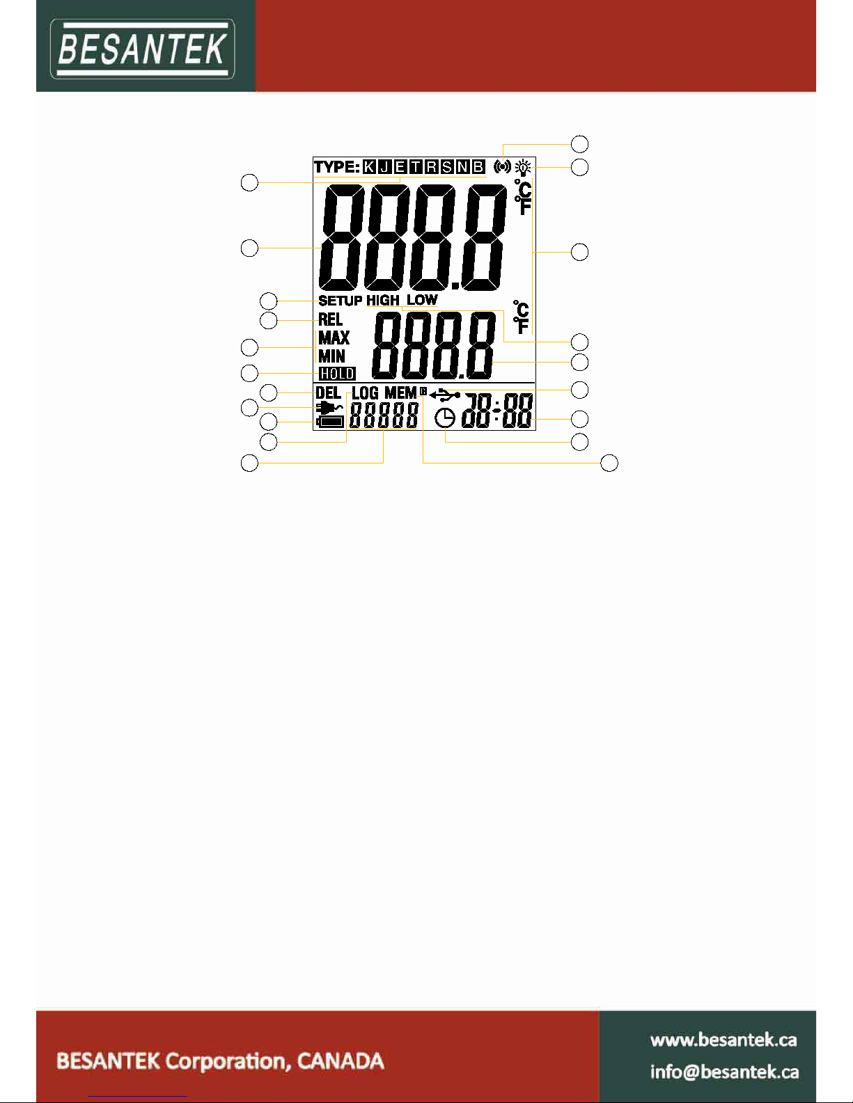
1.5 Single-channel LCD Screen (BST-DL102)....................................................................................................................... 3
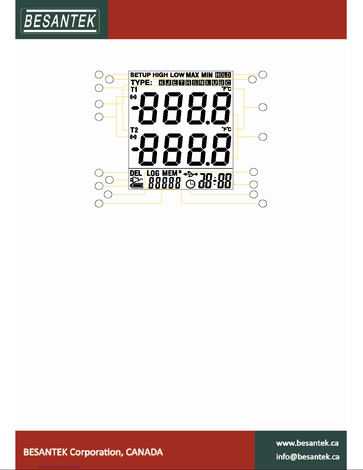
1.6 Two-channel LCD Screen (BST-DL103)..........................................................................................................................4
1.7 Four-channel LCD Screen (BST-DL104)......................................................................................................................... 5
1.8 Buttons..........................................................................................................................................................................6
Chapter 2. BST Software...................................................................................................................... ........................... 7
2.1 Install Driver & Software...............................................................................................................................................7
2.2 Setting the Logger’s Properties to Start a New Measurement.................................................................................... 8
2.3 Properties Description.................................................................................................................................................. 9
2.4 Download the Records after a measurement............................................................................................................ 10
2.5 Data Listing Window.............................................................................................................................. .....................11
2.6 Exporting Logs from Loggpro......................................................................................................................................11
2.7 Delete records in the logger....................................................................................................................................... 12
2.8 Check the Save File in File List.................................................................................................................................... 12
Chapter 3. Attention........................................................................................................................................................ 13
Chapter 4. FAQ....................................................................................................... .......................................................... 14
4.1 LCD Screen Dim...........................................................................................................................................................14
4.2 Recording (LOG) are Automatically Stop.................................................................................................................... 14
4.3 Software "Runtime Error"...........................................................................................................................................14
4.4 Check COM Port Number........................................................................................................................................... 14

1
Chapter 1. BST-DL102 / BST-DL103 / BST-DL104 Hardware
1.1 Introduction
BST-DL102 / BST-DL103 / BST-DL104 are thermocouple thermometers, have proved the stability and the
reliability. It enjoys elegant appearance, large LCD display, backlight function and USB port telecommunication.
Besides, it can support 8 types thermocouple sensors (such as K, J, E, T, N, S, R, B), measuring -200degC to
1800degC with different sensor type suitable for the exact applications. BST-DL102 / BST-DL103 / BST-DL104
with BESANTEK specialized BST Software is easy to operate and quite convenient, widely applied in industrial
production fields, food processing industry, pharmaceutical industry and research testing fields as well as other
temperature monitoring applications.
1.2 Application
Oven
High Temperature Liquid
1.3 Multi-channel Thermocouple Thermometers Model
Model Temperature
channel
Measuring
accuracy Auto-Recording(LOG-capacity) Manual-recording
(MEM-capacity)
BST-DL102 1 ±0.1 ‰+0.5℃36000 88
BST-DL103 2 ±0.1 ‰+0.5℃36000 88
BST-DL104 4 ±0.1 ‰+0.5℃36000 88
Notice: The accuracy on the above table is only the accuracy for thermometer itself. The precision in the
practical applications has relation with the accuracy of thermocouple that customers adopt. Please avoid
adopting inferior thermocouple plug in case of any i terminal damage to thermometers.

2
1.4 Appearance
1- LCD display 9- Manual recording function button
2- Log button 10- Model label
3- Setup button 11- USB port & DC power Jack (9V, 3.5mm)
4- ON/OFF 12- Hole for fixed frame
5- OK button under the setup mode, and
backlight button under
normal working mode
13- Battery cover
6- Maximum and minimum checking buttons 14- BST-DL102 cap(sensor port)
7- Manual recording data checking button 15- BST-DL103 cap(sensor port)
8- The previous data checking button 16- BST-DL104 cap(sensor port)

3
1.5 Single-channel LCD Screen (BST-DL102)
1
2
3
4
5
6
7
8
9
11
10
12
13
14
15
16
18
19
20
17
1- Sensor type symbol display area. 11- Count for auto-recording and manual-recording
data
2- Temperature data display area 12- This symbol shows being the manual-recording
checking status
3- This symbol shows being the setup status 13- Clock symbol
4- This symbol shows being the manual recording
data checking status
14- Time display area
5- This symbol shows being the maximum and
minimum data checking status
15- This symbol shows instruments being the
connection status with PC.
6- This symbol shows being the holding fixed
measuring data status
16- Maximum and minimum data display area
7- This symbols shows that data can be deleted 17- This symbol shows being the maximum or
minimum data checking status
8- This symbol shows instrument is supported by
external DC power
18- Symbol for temperature unit.
9- Battery status indication 19- This symbol shows being the backlight status.
10- This symbols shows being the logging status. 20- This symbol shows the setting limits are being
exceeded.

4
1.6 Two-channel LCD (BST-DL103)
12
4
5
3
6
7
8
10 11
12
13
14
9
15
16
17 18
1- This symbol shows being the setup mode 10- Count for manual-recording or auto-recording
data
2- This symbol shows being the
maximum/minimum data checking status
11- This symbol shows being the
manual-recording data checking status
3- Sensor type symbol display area 12- Symbol for clock
4- Symbol for channel 1 and channel 2 13- Year/month-date/clock alternate display area
5- This symbol shows that the setting limits for
channel 1 or channel 2 are being exceeded
14- This symbol shows that instrument is being
connected with PC
6- This symbol shows manual-recording data
can be deleted
15- Display area for channel 1 and channel 2
7- This symbol shows that the instrument is
being supported by DC external power
16- Symbols for temperature unit for channel 1
and channel 2
8- Battery status indication 17- This symbol shows being the maximum or
minimum data checking status
9- This symbol shows being the logging status. 18- This symbol shows being the holding fixed
measuring data status

5
1.7 Four-channel LCD Screen (BST-DL104)
12
3
4
5
6
7
8
1 0 1 1
1 2
1 3
1 4
9
1 6
1 7 1 8
1 5
1- This symbol showing being the setup mode 10- Count for auto-recording or manual-recording
data
2- This symbol shows being the maximum or
minimum data checking status
11- This symbol shows being the manual-recoding
data checking status
3- Sensor type symbol display area 12- Symbol for clock
4- T1,T2,T3,T4 for channel 1, channel 2,
channel 3 and channel 4 respectively
13- Year/month-date/time alternate display area
5- Data symbol for channel 1, channel 2,
channel 3 and channel 4
14- This symbol shows that instrument is being
connected with PC
6- This symbol shows that manual-recording
data can be deleted
15- This symbol shows setting limits are being
exceeded
7- This symbol shows that instrument is being
connected with PC
16- Temperature unit for channel 1, channel 2,
channel 3 and channel 4
8- Battery status indication 17- This symbol shows being the maximum and
minimum data checking status
9- This symbol shows instrument is being the
logging status.
18- This symbol shows being the holding fixed
measuring data status

6
1.8 Buttons
Buttons Introduction for buttons operation
Click to turn on the instrument and press long for 3 seconds to turn it off.
Automatic shutdown in 15 minutes.
Click to enter into the logging mode, click again to exit the LOG(auto-recording) mode.
Click to enter into the setup mode, click again to exit the current mode and save the
settings.
1、℃/℉switching button,usually ℃, switch ℃/℉,℉ lighting,OK to enter
into the next setting mode
2、SETUP DEL MEM :show DIS in the LCD corner means CAN’T,switch,
show En and press OK to delete the manual-recording data
3、SETUP DEL LOG :show DIS in the LCD corner means CAN’T,switch,
show En and press OK to delete auto-recording data
4、SETUP TYPE:lighting from K,moving on one by one,OK key to confirm
the sensor type.
Setup switch button during the setup mode
Backlight button during the normal working mode
Direction button during the setup mode
Maximum/minimum data checking button during the normal working mode
Direction button during the setup mode
Button for checking the previous manual-recording data during normal working status.
Direction button during the setup mode
Button for checking the manual-recording data during normal working status, total in 88
(capacity)
Direction button during the setup mode
Holding the fixed measuring data status during the normal working mode

7
Chapter 2. BST Software
(BST V1.2 English Version)
2.1 Install Driver & Software
Windows 64bit please install 64bit-driver.
Please Install BST Software in D:>\

8
2.2 Setting the Logger’s Properties to Start a New Measurement.
1. Connect the data logger to a free USB port on the computer.
1
2. Running BST Software on the PC.
3. From the toolbar select Connect.
2
4. Read the logger’s properties.
5. Set the properties.
6. Sync the properties & time. (The PC time will be synchronized to the logger as well.)
7. From the toolbar select Disconnect
8. Unplug the cable from the logger, and then the logger is in Standby mode
3
.
9. Press button MEM on the logger, manual-record.
10. Press button LOG on the logger, then LOG symbol displays on the screen and the logger begins
auto-record.
1The windows operating system can not handle USB devices being unplugged and plugged back too fast. When
unplugging the logger, wait for about 5 seconds before plugging it in again. If you unplug and plug back a device too quickly,
the computer may stop recognizing any USB devices on that port. If this happens you will have to restart the computer. This
is a windows USB problem and is not related to BST-Software.
2If more than one logger is connected to your computer at the same time, the program will ask you to choose COM port
manually.
3The logger has three modes:1.LOG: In the mode, the logger samples and records data timely.2.Standby: In the mode, the
logger stops to sample and record, but the LCD display is on.3.OFF: In the mode, the logger stops to sample and record,
and the LCD display is off. BST-Software cannot connect to the logger also.
5
46
37

9
2.3 Properties Description
Property Text Description
Name English letters or
Numbers
Name of the logger
SN 10 Characters Must be the same as the one in the label of
logger.
Sampling Interval (s) Number from 1 to 240 Sampling frequency in LCD screen
Log Interval (s) Number from 1 to 86400 Logging frequency.
Logs Count The count of “LOG” records in the memory.
MANU logs The count of “MEM” records in the memory.
Capacity The total capacity of the logger’s “LOG”
storage.
High & Low Limit When the value over the limit, the buzz will
sounds an alarm.
Offset4 Input positive number to decrease the value.
Input negative number to increase the value.
4Calibrate the logger: The logger is factory calibrated to an accuracy given in the device specifications. However, there
may be times when you wish to adjust the calibration of your logger. BST-Software provides you with the ability to perform a
single point offset calibration. This calibration can be used to increase the accuracy of the logger for a restricted data range.

10
2.4 Download the Records after a measurement.
11. Connect the data logger to a free USB port on the computer.
12. Running BST software on the PC.
13. From the toolbar select Connect.
14. From the toolbar select Download
15. Choose Auto Logs (LOG) or Manu Logs (MEM) to download
Once the data is transferred from the logger to the PC, the data graph will be displayed.
The graph display will be blank if there are not any logs.
15
13 14

11
Tips: Press and hold the left mouse button to drag a box in the graph, when the left mouse button is
released, the graph will be redraw with the data in the selected rectangle area. Click right button, then
the graph will be redrawing with all the data in the logs file.
2.5 Data Listing Window
Click button on the toolbar, and then the data listing window is shown below.
The data pane lists the data samples collected by the logging device.
The column width of each column is adjustable by using the left mouse button and dragging the column the
desired width.
2.6 Exporting Logs from BST-Software
: Export sample data to an Excel file.
: Export sample data to a text file.
: Export graph to a BMP file.

12
2.7 Delete records in the logger
16. From the toolbar select Delete
17. Choose Auto Logs (LOG) or Manu Logs (MEM) to delete
Delete will clear the Logger’s LOG/MEM Record. It has no effect on record in the computer.
2.8 Check the Save File in File List
The file list pane lists all the files in the directory Logfiles which is located in the installed directory of
BST-Software.
17
16

13
Double click left mouse button, then the selected file is opened.
Click right mouse button, a popup menu is shown as below, you can rename or delete or log file.
The save file is saved in the BST-Software’s installation path in the PC’s hard driver.
Chapter 3. Attention
BST-DL102/BST-DL103/BST-DL104 are not waterproof. Do not connect loggers with computer when the
logger is on water.
BST-DL102/BST-DL103/BST-DL104 plastic shell is ABS, flame retardant, not resistant to acid and alkali.
If repair is needed, only authorized technician could do the repair.
The instrument configuration by 1 x 6LR61 (9V) battery is not rechargeable.
USB power supply (5V) cannot let the Data Logger work.

14
Chapter 4. FAQ
4.1 LCD Screen Dim
Reason:
Insufficient battery or the environment temperature is too low or too high.
Solution:
In the case of insufficient battery, please replace the battery. If resulted from environment temperature,
please immediately take the logger out of the environment.
4.2 Recording (LOG) are Automatically Stop
Reason:
When the battery level is low, there will not be sufficient power to support recording function of the logger.
Solution:
Replace the battery.
4.3 Software "Runtime Error"
Reason:
OS forbid software creating files.
Solution:
Run the program (software) as an administrator.
Install software in Disk D:\
A data logger name cannot contain any of the following characters: \ / : * ? " < > |
Software’s installation path cannot include Chinese character or garbage character.
4.4 Check COM Port Number
Press “Win” + “R” in keyboard -> Run "devmgmt.msc" to Open "Device Manager" in Windows-> Expand
"Ports (COM & LPT)" -> "USB-SERIAL CH340 (COM No.)" is the Data Logger
This manual suits for next models
2
Table of contents
Other Besantek Thermometer manuals