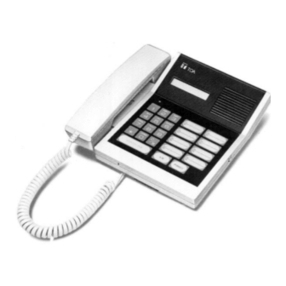
Sentex SPECTRUM Series Installation manual

Doc 6001573
Rev A
SPECTRUM
TELEPHONE ENTRY SYSTEM
PROGRAMMING INSTRUCTIONS
(-101/301 BOARD)
IMPORTANT NOTE
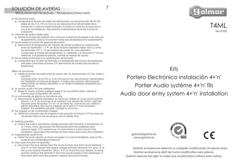
These programming instructions are for a Spectrum system with a -101 or -301 board only.


Rev A Doc 6001573 Page 1 of 15
IMPORTANT NOTICE
The Spectrum systems are very reliable and easy to use. However, if programmed incorrectly the systems
may not work properly. Before attempting to program and use these systems, you should become familiar
with them by reading the instructions in this manual. You can also use the space provided in the manual to fill
in the entries before you program them into your system. If you have any questions concerning these
instructions, please contact your installing dealer.
TABLE OF CONTENTS
This document is divided into seven sections and one appendix as follows:
SECTION NAME PAGE
1. Overview of System Operation 2
2. Entering and Exiting the Programming Mode 3
3. Basic Hints and Programming Rules 4
4. Setting System Characteristics 5
5. Entering and Erasing Telephone Numbers and Entry Codes 10
6. Remote Programming 13
Appendix 1 14
IMPORTANT: The Sentex Systems warranty on this system is conditioned upon Sentex Systems being paid in full for this
equipment. This warranty will not be honored until such payment has been received by Sentex Systems.
COPYRIGHT 2001
ALL RIGHTS RESERVED
THIS DOCUMENT IS PROTECTED BY COPYRIGHT, AND MAY NOT BE COPIED OR ADAPTED WITHOUT THE
PRIOR WRITTEN CONSENT OF SENTEX. THIS DOCUMENT CONTAINS INFORMATION PROPRIETARY TO
SENTEX AND SUCH INFORMATION MAY NOT BE DISTRIBUTED WITHOUT THE PRIOR WRITTEN CONSENT OF
SENTEX. THE FIRMWARE INCLUDED IN THE SPECTRUM SYSTEMS AS THEY RELATE TO THIS
DOCUMENTATION ARE ALSO PROTECTED BY COPYRIGHT AND CONTAIN INFORMATION PROPRIETARY TO
SENTEX.
Visit us at www.sentexsystems.com

Page 2 of 15 Doc 6001573 Rev A
1 - OVERVIEW OF SYSTEM OPERATION
Your Spectrum telephone entry system stores, recalls, and dials the telephone numbers of your building's
residents/occupants (hereinafter referred to as resident or residents), and responds to signals from their
phones to unlock a door or activate an automatic gate operator. When a visitor arrives at the controlled
entrance, he/she lifts the receiver (if you have a model with a handset), pushes the "#" button on the keypad to
activate the system, and then dials the code that is listed next to the resident's name on the directory. The
resident can then initiate one of four actions by pressing a key on their telephone. These actions are as
follows:
KEY PRESSED ACTION INITIATED
9 Opens door 1 (on either a tone or a rotary dial telephone).
5 Opens door 2 (on a tone dialing telephone only).
# Extends the amount of time you may talk with a visitor.
∗Denies entry to the visitor and disconnects the visitor call.
When you dial a “9” or a “5”, the controlled entrance unlocks, the display exhibits an “open” indication, and
the system emits a 3-second tone. When allowing entry, neither party should hang up until the display and
tone are activated. It is important that all residents know how the system operates.
The system also has a feature that allows it to be used with codes that, when entered on the system's
keypad, can latch, cycle, or release either of the system’s relays. These 4-digit entry codes can be given to
(or chosen by) each resident as well as 10 vendors, service people, etc. Conversely, you can decide to limit
the use of this feature to a few people. An authorized person who wishes to enter the building by this means
presses the "∗“ key and their 4-digit code. If a valid code is entered, the controlled entrance will unlock or
activate in the manner described in the paragraph above. If invalid codes are entered successively (the
number of incorrect successive entries allowed can be set between 1 and 9) within a 3-minute period, this
feature will disable itself for 3-minutes while the remainder of the system's capabilities will continue to operate
normally.
For your convenience, a programming guide label has been placed on the inside of the system's cabinet.
This guide is an easy, handy reference for you once you become familiar with the programming procedures.

Rev A Doc 6001573 Page 3 of 15
2 - ENTERING AND EXITING THE PROGRAMMING MODE
ENTERING THE PROGRAMMING MODE
The programming password is a 6-digit number. The password is set to “000000” at the
factory, but your installer may have changed it during installation. When you are comfortable
with programming, you should change the password to maintain the security of your system.
Make a note of the new password so you do not forget it.
To enter the programming mode from the keypad, enter three asterisks “∗∗∗“ followed by the
six-digit password. The unit will respond with 2 short beeps.
EXITING THE PROGRAMMING MODE
After you have completed programming your system, exit the programming mode by
pressing “00” + “#.”

Page 4 of 15 Doc 6001573 Rev A
3 - BASIC HINTS AND PROGRAMMING RULES
The sections that follow provide detailed explanations of how to program specific functions into the system.
The following programming rules and hints typically apply when programming is completed. However, there
are several basic hints and programming rules that apply to programming the system remotely. If you wish to
program the system remotely, please refer to section 7 of this manual.
Basic hints and programming rules for the Spectrum system are as follows:
1. After you complete a valid programming sequence, the system will return the
programming prompt “P” to the display. You can then switch to another
programming area or continue on with the area you just completed.
2. Several error codes are used to help ensure that you program the system correctly.
The system will display an "E" and a 1-digit code to tell you what you have done
wrong. These error codes are shown below:
CODE MEANING OF CODE
1 The entry you are trying to erase or verify does not exist in the
system. For example, there is no directory code that matches the
one you are trying to erase.
2 You have tried to enter a directory code or entry code that
already exists in the system's memory. For example, you are
trying to enter directory code 253 and that code has already been
assigned to someone else.
3 The system memory is full. You must either erase an individual
entry that has already been made or erase the whole memory.
5 You have made a format error in making the entry. For example,
you tried to enter a “∗“ as part of a telephone number.
An "E" will also appear when the system is used incorrectly during normal operation.
3. If you realize during an entry that you are making a mistake, you can cancel the
entry by pressing the “∗“ key.

Rev A Doc 6001573 Page 5 of 15
4 - SETTING SYSTEM CHARACTERISTICS
The programming sequences described in this section allow you to set up the characteristics of your
telephone entry system. In general, you should only need to program your system during installation, not on
an on-going basis. Make sure you are in the programming mode before you start programming.
SETTING THE PROGRAMMING PASSWORD (STEP 01)
Purpose To change the code used to enter the programming mode.
Factory
Setting 000000.
Format 01 + programming password (6 digits) + #.
Example 01 + 123456 + # (sets the programming password to 123456).
Note: Be sure to change your code to one that only you know and is easy to
remember.
VERIFYING THE PROGRAMMING PASSWORD (STEP 02)
Purpose To verify the programming password.
Format 02 + programming password (6 digits) + #.
Note Once you press the “#” key, the system will either display a “1” or a “0”. If
the system responds with a “1”, the programming password you entered
matches the password in the system’s memory. If the system responds
with a “0”, the programming password is incorrect and you need to repeat
step 01 before exiting the programming mode.
SETTING THE DIALING TYPE (STEP 03)
Purpose To set the dialing type to tones or pulses in order to enable/disable the
shared phone feature and display options such as tone/pulse and
shared phone.
Format 03 + type of dialing (one digit) + #
03 + # (1 is displayed for tone dialing, 0 is displayed for pulse dialing)
Example 03 + 1 + # (sets the dialing type to tones)
03 + 0 + # (sets the dialing type to pulses)
03 + # (displays whether dialing type is set to tones or pulses.
Note The factory default is ‘1’ for tone dialing.

Page 6 of 15 Doc 6001573 Rev A
VERIFY THE DIALING TYPE (STEP 03)
Purpose To verify that the dialing type is either a tone or a pulse
Factory setting = ‘1’
Format 03 + #
Note Once you press the “#” key, the display will show that the dialing type is
either 1 for tone or 0 for pulse.
SETTING RINGS BEFORE ANSWER (STEP 04)
Purpose To set the number of times the phone will ring before the system answers
it. The number of rings can be from 0 to 9. Factory setting = 2
Format 04 + n + # number of rings (0 <=n <=9) + #.
Example 04 + 4 + # (sets the number of rings to 4).
VERIFY RINGS BEFORE ANSWER (STEP 04)
Purpose To verify the number of times the phone will ring before the system
answers it. The number of rings can be from 0 to 9. Factory setting = 2
Format 04 + #
Note Once you press the “#” key, the display will show the number of times the
phone will ring before the system answers it.
SETTING THE VISITOR TALK TIME (STEP 05)
Purpose To set the maximum length of a call that can be made by a visitor. This
length can be set from 15 to 255 seconds.
Factory setting = 60 seconds.
Format 05 + number of seconds (up to 3 digits) + #.
Example 05 + 45 + # (sets the talk time to 45 seconds).
VERIFYING THE VISITOR TALK TIME (STEP 05)
Purpose To verify the maximum amount of time a visitor can stay on a visitor call.
Format 05 + #.
Note Once you press the “#” key, the display will show the maximum number
of seconds allowed for a visitor call.

Rev A Doc 6001573 Page 7 of 15
SETTING THE PBX DIGIT (STEP 06)
Purpose To dial a digit (which you specify) if your system is connected to a PBX
telephone system, and then pause briefly (so the PBX can give the
system an outside line) before dialing the telephone number that you
program into the system.
Format 06+ PBX Digit (1 digit) + #.
Example 06 + 9 + # (sets the system to dial a “9” before the telephone number).
VERIFYING THE PBX DIGIT (STEP 06)
Purpose To verify the digit you specified to give the system an outside line if your
system is connected to a PBX telephone system.
Format 06 + #.
Note Once you press the “#” key, the display will show the digit you specified if
your system is connected to a PBX telephone system.
ERASING THE PBX DIGIT (STEP 06)
Purpose To erase the PBX digit from the system’s memory. Once the PBX digit is
erased, the system will dial a telephone number without the preceding
digit and pause.
Format 06 + 101010 + #.
SETTING THE RELAY ACTIVATION TIME (STEP 07)
Purpose To control the amount of time the door or gate will remain
unlocked/open. The open time can be set from 01 to 99 seconds.
Factory setting = 10 seconds for each relay.
Format 07 + number of seconds for door 1 (2 digits) + number of seconds for
door 2 (2 digits) + #.
Example 07 + 05 + 60 + # (sets door 1 unlocked/open time for 5 seconds and
door 2 unlocked/open time for 60 seconds).
Note If this relay activates a gate operator with a momentary contact closure,
you will need to set the relay activation time for a short period of time (for
example, 5 seconds). If you set the relay activation time for a longer
period of time, there is a possibility that the gate will continue to open
and close until the relay activation period has ended.

Page 8 of 15 Doc 6001573 Rev A
VERIFYING THE RELAY ACTIVATION TIME (STEP 07)
Purpose To verify the amount of time the door or gate will remain open.
Format 07 + #
Note Once you have pressed the “#” key, the display will show four digits. The
first two digits are the amount of time the door or gate attached to relay 1
will remain open and the remaining two digits are the amount of time
relay 2 will remain open.
SETTING DIRECTORY CODE LENGTH (STEP 08)
Purpose To tell the system how many digits will be in the code that a visitor uses
to dial a resident. Factory setting = 2 digits.
Format 08 + code length (may be 1, 2, 3, or 4) + #.
Example 08 + 3 (sets code length to 3 digits) + #.
Notes WARNING: Be sure the directory code length is set properly before you
begin entering telephone numbers. You may change this length later
BUT you will have to change all directory codes in the system to the new
length or the system will not function properly and you may run out of
capacity.
A 1-digit code length will handle up to 10 codes, 2-digit codes will handle
up to 100 codes, and 3- or 4-digit codes will handle up to 1000 codes.
VERIFYING DIRECTORY CODE LENGTH (STEP 08)
Purpose To verify that the code length in the system is what you think it is/want it
to be.
Format 08 + #.
Note Once you press the "#" key, the display will show the number of digits in
the directory code. For example, if you have 3 digits in the directory
code, a “3” will be shown on the display when you press the “#” key.

Rev A Doc 6001573 Page 9 of 15
USING THE RELAY MANAGEMENT FUNCTIONS (STEPS 71 through 79)
Purpose To allow you to either activate or deactivate a specified relay while in the
programming mode.
Format 7 + relay command code (1 digit) + #.
Relay
Command 1 = Cycle relay 1 for its programmed period of time.
Codes 2 = Cycle relay 2 for its programmed period of time.
3 = Latch relay 1 for an unspecified amount of time.
4 = Latch relay 2 for an unspecified amount of time.
5 = Release relay 1 from its latched state.
6 = Release relay 2 from its latched state.
7 = Cycle both relays for their programmed period of time.
8 = Latch both relays for an unspecified amount of time.
9 = Release both relays from their latched state.
Example 7 + 2 + # (cycles relay 2 for its programmed period of time).
Important If you select relay action code “9” and only one of the relays are currently
Notes latched, this step will not affect the status of the unlatched relay.

Page 10 of 15 Doc 6001573 Rev A
5 - ENTERING, VERIFYING AND ERASING
TELEPHONE NUMBERS AND ENTRY CODES
The programming sequences described in this section allow you to tell the system what telephone numbers
it may dial, and which 4-digit entry codes should grant entry. These programming steps will be repeated
frequently as people move in and out of your building. Make sure you are in the programming mode before
you start programming.
SETTING DIRECTORY CODES
AND TELEPHONE NUMBERS (STEP 09)
Purpose To tell the system to dial up to an 12-digit telephone number when the
directory code (the code that appears next to the name on the directory)
you program is entered on the keypad by a visitor.
Format 09 + directory code (see page 4 for number of digits) + telephone
number (up to 12 digits) + #.
Examples 09 + 38 + 5551212 + # (sets code 38 to dial 555-1212).
09 + 24 + 18185556978 + # (sets code 24 to dial 1-818-555-6978).
Notes The directory code length you use must be the same for all residents.
This length is set in the area discussed on page 4 entitled "Setting
Directory Code Length".
If you are going to change a resident's telephone number or assign a
directory code that has previously been used to a new resident, you
must first erase the existing entry and then make the new entry. (See
the area below entitled "Erasing Directory Codes/Telephone Numbers".)
VERIFYING TELEPHONE NUMBERS (STEP 09)
Purpose To check that you have entered a telephone number correctly.
Format 09 + directory code + #.
Example 09 + 38 + #
Note Once the “#” key is pressed, the system will display the telephone
number that was entered for that directory code. If the telephone number
shown is incorrect, erase the entry as shown on page 6 and re-enter it
with the correct telephone number.
ERASING DIRECTORY CODES
AND TELEPHONE NUMBERS (STEP 10)
Purpose To delete a directory code/telephone number entry from memory.
Format 10 + directory code + #.
Example 10 + 38 + # (erases directory code 38 and its associated telephone
number).

Rev A Doc 6001573 Page 11 of 15
ERASING ALL DIRECTORY CODES
AND TELEPHONE NUMBERS (STEP 11)
Purpose To Allow you to clear the entire directory code/telephone number
memory. You would want to perform this task if the memory has become
filled with numbers that have been forgotten or have been entered in
error.
Format 11 + 101010 + #.
SETTING NUMBER OF WRONG ENTRY CODES ALLOWED (STEP 12)
Purpose To tell the system how many incorrect entry codes may be entered
within a 3 minute period before the system deactivates the entry code
function for a period of 3 minutes. All other functions continue to
operate normally during this time. The number of wrong entries can
be between 0 to 9 incorrect entries. A “0” will disable this feature.
Factory setting = 2 incorrect entries.
Format 12 + number of incorrect entry codes allowed (1 digit) + #.
Example 12 + 6 + # (sets incorrect entry codes allowed at 6).
Note When an incorrect entry code is entered on the system’s keypad, the
system will respond with an “E” error message on the display. When the
specified number of incorrect entry codes is reached, the system will not
give an error indication on the display. The only indication given by the
system that the incorrect entry code limit has been reached is that the
system will not accept any entry code entries until the 3 minute period is
over.
VERIFYING THE NUMBER
OF INCORRECT ENTRY CODES ALLOWED (STEP 12)
Purpose To verify the number of incorrect entries that are allowed on the system’s
keypad before the system deactivates the keypad function for 3 minutes.
Format 12 + #.
Notes Once you press the “#” key, the display will show the number of incorrect
entries allowed. For example, if you have this feature set at 4 entries, the
display will show a “4” after the “#” key is pressed.
PROGRAMMING ENTRY CODES + RELAY ACTION CODE (STEP 13)
Purpose To Allow you to set up 4-digit codes that residents or service people can
use to gain entry to the building without a key. There are two types of
entry codes that you may enter: entry codes with programmed relays
and “simple” entry codes. Entry codes with programmed relays allows
you to specify which relay the code will activate and how it is activated
when it is entered on the system’s keypad. “Simple” entry codes will only
activate relay 1 for its programmed period of time.

Page 12 of 15 Doc 6001573 Rev A
Format Entry code with programmed relay - 13 + entry code (4 digits) + relay
code (1 digit) + #.
Simple entry code - 13 + entry code (4 digits) + #.
Relay 1 = Cycle relay 1 for its normal activation time.
Code 2 = Cycle relay 2 for its normal activation time.
3 = Latch relay 1 for an unspecified period of time.
4 = Latch relay 2 for an unspecified period of time.
5 = Release relay 1 from its latched state.
6 = Release relay 2 from its latched state.
7 = Cycle both relays open for their normal activation time.
8 = Latch both relays open.
9 = Release both relays from their latched states.
Example Entry code with programmed relay - 13 + 5467 + 4 + # (sets up entry
code 5467 to latch relay 2).
Simple entry code - 13 + 3377 + # (sets entry code 3377 to activate relay
1 for its programmed period of time).
Note You have the capacity to give entry codes to each resident in your
building up to the capacity purchased, plus at least 10 extra for vendors
or service people. Ask your installing dealer for the exact number of
entry codes available.
ERASING ENTRY CODE (STEP 14)
Purpose To delete a 4-digit code that a resident or service person
uses to gain entry to the building without a key.
Format 14 + entry code (4 digits) + #
Example 14 + 5467 + # (deletes entry code 5467).
ERASING ALL ENTRY CODES (STEP 15)
Purpose To allow you to clear the entire entry code memory. You would want to
perform this task if the memory has become filled with codes that have
been forgotten or have been entered in error.
Format 15 + 101010 + #.

Rev A Doc 6001573 Page 13 of 15
6 - REMOTE PROGRAMMING
To program the Spectrum system via telephone from a remote location, please refer to the following
instructions:
REMOTE PROGRAMMING FROM A TONE TELEPHONE
1. Dial the unit telephone number and wait for an answer. When the unit answers, it
emits two beeps.
2. Enter one asterisk “∗“ and the six-digit password. The unit will begin emitting a
high-pitched tone. Press the “#” key to stop the tone.
3. Once you are in the programming mode, a “b” appears on the unit’s display and two
short tones are emitted to signal that the unit is ready to be programmed.
4. Begin programming exactly the same as you would using the keypad on the unit.
NOTE The only functions that will not work from a remote location are the verify
functions and the ability to set the system’s feedback.
REMOTE PROGRAMMING VIA MODEM
The –101/–301 board has a modem and can be programmed remotely using this modem and SVWin
software. Please refer to the SVWin User’s Guide for programming instructions.

Page 14 of 15 Doc 6001573 Rev A
APPENDIX 1
PROGRAMMING STEPS FOR THE 101/301 BOARD
Step number Description Example Description Remote
Prgrm?
Error Messages:
E1: does not exist
E2: duplicate found
E3: system is full
E5: format error
00 Terminate Programming 00+# Yes
01 Set Password 01+nnnnnn+# Yes
02 Verify Password 02+nnnnnn+# 1=nnnnnn matches current
setting, 0 = no match
No
03 Set Dialing Type 03+n+# Sets dialing type to tones
(1), pulses (0)
Yes
03 Verify Dialing Options 03+# (1/0 for tone/pulse) No
04 Set Rings Before Answer 04+n+# Sets rings before answer to
0 <=n <=9
Yes
04 Verify Rings Before Answer 04+# If 0, don’t answer No
05 Set Visitor Talk Time 05+n+# 015 <=n <255 Yes
05 Verify Visitor Talk Time 05+# No
06 Set PBX Digit 06+n+# Set PBX digit Yes
06 Verify PBX Digit 06+# Display PBX digit No
06 Erase PBX Digit 06+101010+# Erase PBX digit Yes
07 Program Relay Activation Time 07+r1+r2+# Sets relay 1 to r1 (2 digits)
and relay 2 to r2 (2 digits)
Yes
07 Verify Relay Activation Time 07+# No
08 Set Directory Code Length 08+n+# Sets code length to 1 <= 4
digits 1<=n <=4
Yes
08 Verify Directory Code Length 08+# No
09 Program Directory Code and
Phone Number
09+d[ddd]+t[ttt
tttttttt]+#
Sets code d[ddd] (1-4 digits)
to t[ttttttttttt] up to 12 digits
Yes
09 Verify Directory Code and
Phone Number
09+d[ddd]+# No
10 Erase Directory Code and
Phone Number
10+d[ddd]+# Erases dir code d[ddd] (1-4
digits)
Yes
11 Erase All Directory Codes and
Phone Numbers
11+101010+# Erases all dir codes Yes
12 Set # of wrong entry codes 12+n+# Sets incorrect entry codes
allowed to 0 <=n <=9
Yes
12 Verify # of wrong entry codes 12+# If n=0, strikes and out is
disabled
No
13 Program Entry Code 13+eeee+# Sets entry code eeee with
relay action code 1
Yes
13 Program Entry Code + Relay
Action Code (RAC)
13+eeee+r+# Sets entry code with
specified relay action code
‘r’
Yes
14 Erase Entry Code 14+eeee+# Erases entry code eeee (4
digits)
Yes
15 Erase All Entry Codes 15+101010+# Erases all entry codes Yes
52 System Reset
69 Set Feedback 69+# No
7r (see Relay Action
Codes, next page)
Relay Management Functions 7+r+# Performs the specified relay
action ‘r’
Yes

Rev A Doc 6001573 Page 15 of 15
* Relay Action Codes
DIGIT RELAY ACTION CODE
1 Cycle Relay 1
2 Cycle Relay 2
3 Latch Relay 1
4 Latch Relay 2
5 Release Relay 1
6 Release Relay 2
7 Cycle Both
8 Latch Both
9 Release Both
NOTE The -101/-301 board has the ability to cycle, latch and/or release either relay during programming.
Table of contents
Other Sentex Intercom System manuals


