Probewell ST-3 User manual

USER GUIDE

© Copyright 2021 by Probewell Lab Inc. Printed in Canada.
All rights reserved, including those to reproduce this manual or parts thereof, in any form
without the express written permission of Probewell Lab Inc.
ST-3/XT3
User Guide
Version 1.1 –May 2021
IT IS ESSENTIAL THAT OPERATORS THOROUGHLY READ THIS INSTRUCTION
MANUAL BEFORE PUTTING THIS PRODUCT INTO SERVICE.

Probewell Lab Inc.
Page • 2
Limited Warranty
Your ST-3/XT3 comes with a two-year hardware warranty. Probewell Lab Inc.,
(Probewell) warrants this ST-3/XT3 against defects in materials and
workmanship for a period of two (2) years from the date of purchase from
Probewell. This warranty applies only to the original purchaser of the ST-3/XT3
and is not transferable.
All accessories come with a two-year hardware warranty. Probewell warrants
all accessories against defects in materials and workmanship for a period of two
(2) years from the date of purchase from Probewell. This warranty applies only
to the original purchaser and is not transferable.
This warranty does not cover any damages caused neither by negligence, non-
authorized modifications, or parts installed without prior written permission
from Probewell.
This warranty does not apply if the product has been damaged by accident,
abuse, misuse, or misapplication, nor as a result of service to the product by
anyone other than Probewell.
PROBEWELL IS NOT RESPONSIBLE FOR ANY LOST PROFITS, LOST SAVINGS OR
OTHER INCIDENTAL OR CONSEQUENTIAL DAMAGES ARISING OUT OF THE USE
OF OR THE INABILITY TO USE THIS PRODUCT. THIS INCLUDES DAMAGE TO
PROPERTY AND DAMAGES FOR PERSONAL INJURY. THIS WARRANTY IS IN LIEU
OF ALL OTHER WARRANTIES, INCLUDING IMPLIED WARRANTIES OF
MERCHANTABILITY AND FITNESS FOR A PARTICULAR PURPOSE.
Disclaimer
Probewell Lab Inc., (Probewell) reserves the right to make changes to this
document and the products it describes without notice. Probewell shall not be
liable for technical or editorial errors or omissions made herein; nor for
incidental or consequential damages resulting from the furnishing,
performance, or use of this material.
Features and specifications are subject to change without notice.

ST-3/XT3 User Guide
Page • 3
Table of Contents
Limited Warranty......................................................................................... 2
Disclaimer.................................................................................................... 2
Table of Contents ........................................................................................ 3
Chapter 1
Introduction..................................................................................................7
ST-3/XT3 Overview ...................................................................................... 7
Chapter 2
Description....................................................................................................9
ST-3/XT3 tester............................................................................................ 9
Front/Rear View of the ST-3/XT3..................................................... 10
Side View of the ST-3/XT3................................................................ 11
Theory of Operation.................................................................................. 13
Power Quality .................................................................................. 13
Primary/Secondary Analysis (CT/PT Ratio and Phase Shift)............. 14
CT Burden ........................................................................................ 14
Admittance ...................................................................................... 15
Accessories ................................................................................................ 16
ST-3/FLEX-CT.................................................................................... 16
ST-3/PT600....................................................................................... 16
ST-3/ALW ......................................................................................... 17
ST-3/VLW ......................................................................................... 17
ST-3/EXT........................................................................................... 17
Chapter 3
Operation....................................................................................................19
Summary ................................................................................................... 20
Installing the ST-3/XT3............................................................................... 21
Connecting to the ST-3/XT3....................................................................... 23
Running the Application ............................................................................ 24
Available Tests........................................................................................... 25
Test Examples............................................................................................ 26
Example 1: Power Quality Test: Form 9S Wye with 3CT and 3PT .... 27
Example 2: Primary/Secondary Analysis (CT Ratio Test): Form 3S
Single-Phase with CT........................................................................ 29
Example 3: Burden Test Form 5S Delta with CT............................... 31
Example 4: Admittance: form 9S Wye ............................................. 34
Accuracy Test............................................................................................. 35

Probewell Lab Inc.
Page • 4
Appendix A
Specifications................................................................................................... 37
Appendix B
Form Configurations........................................................................................ 39
Appendix C
Powering the Unit in the Laboratory ............................................................... 41
Appendix D
Customer Service............................................................................................. 43
Appendix E
Recommendations........................................................................................... 45

ST-3/XT3 User Guide
Page • 5
List of Abbreviations
Abbreviation
Complete term
A
Ampere
Amp
Ampere
AC
Alternating current
CFM
Cubic feet per minute
CSV
Comma-separated values
CT
Current transformer
DSP
Digital signal processor
I
Current
kW
Kilowatt
Lb
Pound(s)
NIST
National Institute of Standards and Technology
P
True power
PF
Power factor
PPE
Personal protective equipment
PPI
Pore per inch
PQ
Power quality
PT
Potential transformer (same as VT)
Q
Reactive power
RMS
Root mean square
S
Apparent power
THD
Total harmonic distortion
U
Voltage
V
Volt
VAR
Volt-ampere reactive (same as Q)
VA
Volt-ampere (same as S)
VAC
Volt AC (same as Vrms)
VDC
Volt direct current
VT
Voltage transformer

Probewell Lab Inc.
Page • 6
W
Watt (same as P)
Wh
Watthour
WiFi
Wireless fidelity
µWh
Micro-watthour
µVARh
Micro-VARhour

ST-3/XT3 User Guide
Page • 7
Chapter 1
Introduction
The Probewell Lab ST-3/XT3 is the first socket-type transformer-rated
site tester with built-in WiFi technology.
ST-3/XT3 Overview
The ST-3/XT3 tester weighs only 4.5 lb, making it an ideal tool for field
testing. With the ST-3/XT3, field technicians can accurately test a CT/PT
instrument-rated installation in mere minutes. The ST-3/XT3 can
perform Power Quality (PQ) tests, Real Time Waveform analyses,
Voltage (V) and Current (I) Phase Angle tests, Total Harmonic Distortion
(THD) analyses, CT/PT Ratio and Phase Shift tests, Burden tests and
Admittance tests.
The ST-3/XT3 comes in a shock-resistant carrying bag with room for the
unit, cable accessories and adapters.
The kit includes:
•ST-3/XT3 tester
•11 removable twist tabs
o5 small tabs installed on the ST-3/XT3
o5 small spares in the pocket inside the carrying bag
o1 big tab for a specific 3S installation (5 o'clock position)
•Adapter for 5S, 35S and 45S installations
•Update cable
•Connection guidelines
•User guide
•Factory calibration report

Probewell Lab Inc.
Page • 8

ST-3/XT3 User Guide
Page • 9
Chapter 2
Description
The first part of this chapter describes the ST-3/XT3’s hardware. The
second part explains the theory of operation for the tester.
ST-3/XT3 tester
The ST-3/XT3 is cylinder-shaped, designed to be easily inserted into
both ringless and ring-type meter bases.
The ST-3/XT3 contains three current sensors up to 20 Amps to analyze
the secondary current from the meter base.
The rear of the tester has six standard fixed tabs with bypasses that can
be internally rerouted for burden and admittance testing, and five small
and one big (not installed) removable twist tabs, with twist-and-lock
mechanism. The ST-3/XT3 gets its power directly from these back tabs
and accepts an input voltage from 100 to 480 VAC. Voltage above 480
+ 10% will not damage the unit, but it will keep it from starting.
The twist tabs can be placed at positions 5a, 11, 12, 13, 16 and 17 as
required by the meter base where the test is being conducted. The twist
tab at position 12 can be placed in two different positions to hold either
forms 6S/8S/9S or forms 3S/4S. The twist tab at position 16 can be
placed in two different positions to hold either forms 6S/8S/9S or form
4S. The twist tab at position 5a can be used for some 3S installations,
where the jaw is in the 6 o'clock position in the meter base. Refer to
refer to the Form Compatibilities and Configuration Booklet for
complete information.
The front of the tester has two 12-pin connectors for the primary
measurement accessories.

Probewell Lab Inc.
Page • 10
Front/Rear View of the ST-3/XT3
Fig. 2.1
Fig. 2.1 shows the removable twist tabs, which do not require any tools
to be moved from one position to another. The above illustration shows
the twist tabs positioned at 11-12-13 and 16-17.
ST-3/XT3 User Guide
Page • 11
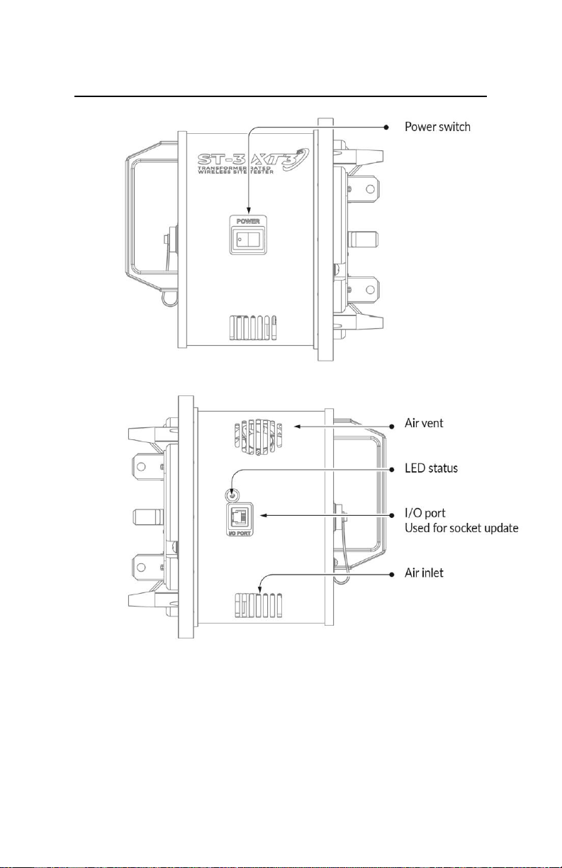
Side View of the ST-3/XT3
Fig. 2.2
Fig. 2.2 LED status: Solid green means the device is ready, blinking green
means a test is underway and blinking red means there is a system
error.

Probewell Lab Inc.
Page • 12
Identification
Description
Current tabs
Connect the ST-3/XT3 tester to the front jaws of
the meter base.
Removable twist
tabs
These tabs can easily be installed in position5a, 11,
12, 13, 16 and 17 as required by the meter base
where the test is being conducted. See the Form
Compatibilities and Configuration Booklet.
Form Selector
In position 3S/4S, the unit is powered from the tab
at position 12 and the current tab at position 2. In
position 6S/8S/9S, the unit is powered from the tab
at position 11 and the current tab at position 2. In
specific situations, tab 17 is used to connect the
neutral to tab 2.
Note: If the 5S adapter is used, the Form Selector
must be set to position 6S/8S/9S
Circuit breakers
Protection for the ST-3/XT3. Two 1 A circuit
breakers, which can easily be reset by pressing a
spring-loaded button.
Power switch
Tester’s main power On/Off switch.
Connectors
There are two 12-pin connectors located on the
front of the ST-3/XT3, for accessories. The one
identified as CT is to connect the primary current
measurement accessory. The second connector
identified as PT is to connect the primary voltage
measurement accessory when PT is used.
I/O port
This connector is only used to update the
ST-3/XT3's firmware.
Air vent(1)
Warm air exit. A 5 CFM miniature fan forces air
circulation inside the unit.
Air inlet(1)
Cool air input. Filtered through a 45 PPI
polyurethane foam filter.
(1) Do not block air circulation. Keep away from direct heat or flame.

ST-3/XT3 User Guide
Page • 13
Theory of Operation
The ST-3/XT3 accurately measures and analyzes CT/PT meter
installations. You can easily conduct Power Quality (PQ) tests,
waveform analysis, phasors tests, Total Harmonic Distortion (THD),
CT/PT ratio, CT Burden and Admittance tests.
Embedded in its core is high-performance, multiphase energy metering
circuity enabling a full RMS and line cycle measurement of both
secondary and primary currents and voltages.
With the ST-3/XT3 installed, and the bypass removed (in the meter
base), the CT is never open as the ST-3/XT3 always keeps the closed
loop on the secondary.
Power Quality
The power quality function gives you all the information collected by
the ST-3/XT3 at the meter base, such as voltages on each phase (U),
current for each phase (I), real power in watts (P), reactive power in VAR
(Q), apparent power in VA (S), the phase angle for the voltage and
current of each phase, the power factor (PF), THD in both voltage and
current, and the frequency.
This test can be conducted with or without primary measurement
accessories.
Phasors
This vectorially graphical function give you the angles between each
phase in current and voltage in relation to the voltage of Phase A.
Waveform analysis
This graphical function gives you a time-based sinewave representation
of the meter base's voltage and current. You can also isolate each phase
to see the relation between the voltage and current. The view displays
two current and voltage cycles.

Probewell Lab Inc.
Page • 14
Total Harmonic Distortion (THD)
This bar graph display gives you the relationship between the
fundamental frequency and all the harmonics up to the 22nd harmonic.
Primary/Secondary Analysis (CT/PT Ratio and Phase Shift)
You must use an accessory to conduct this test.
This test is to ensure that the ratio between the primary current or
voltage and the secondary current or voltage are the same as indicated
on the transformers being tested. It is performed with the accessories
provided with the ST-3/XT3.
Example: if the name plate indicates 400:5 the nominal input current is
400 A and the output at the secondary is 5 A. For example, if the
ST-3/XT3 reads a primary input current of 399 and an output at the
secondary of 4.98A, this gives a ratio of 400:5.
The test can also give the phase relationship between the primary and
secondary.
CT Burden
Current transformer burdens are typically expressed in VA. The burden
test is performed to verify that the CT can supply a known current into
a known burden while maintaining its stated accuracy. A burden test is
typically performed at full-rated secondary current value
(e.g., 5 A or 1 A).
By applying precision resistance in series with the CT secondary, the
ST-3/XT3 verifies the current sample and analyze the deviation in
accordance with the value without resistance.
All the phases (A, B, C) are run sequentially until the maximum burden
value selected in the Probewell Connect application is reached.
This test can be performed with or without a CT accessory, but an
accessory will give the best results since the primary/secondary will be
tracked in real-time. Without a CT accessory, the test takes a snapshot
of the secondary current as its baseline.

ST-3/XT3 User Guide
Page • 15
Admittance
This test is conducted by injecting a small, 1,525 Hz audio frequency
into the CT secondary, then measuring the audio frequency's induced
current to determine the admittance value.
Analog filtering and programmable gain are used to get the best
dynamic range for the DSP to compute the admittance @ 60 Hz. While
CT burden needs secondary current to achieve its purpose, the
admittance needs small or no current (max. 0.5 A) on the secondary
side. If the current is higher than 0.5 A, the test will not be conducted.
All the phases are run sequentially.
This test can be conducted with or without an accessory.

Probewell Lab Inc.
Page • 16
Accessories
The ST-3/XT3 comes with several optional accessories for taking primary
measurements.
ST-3/FLEX-CT
The ST-3/FLEX-CT’s current probes are Rogowski coils, an electrical device for
measuring the primary current of a CT. They consist of a helical coil of wire with
the lead from one end returning through the center of the coil to the other end,
so that both connections are at the same end of the coil. The probe can easily
be placed around the wire going through the CT and be secured with a latch.
The ST-3/FLEX-CT is used for comparing primary to secondary current, with
auto-detection, and is electronically compensated with an accuracy of 0.5% and
a current range up to 2500 A for the ST-3/FLEX-CT2500 and up to 5000 A for the
ST-3/FLEX-CT5000. The window size is 10.67'' (271 mm), the cable is 15 feet
long.
ST-3/PT600
The ST-3/PT600 is an electrical device that converts a high-voltage reading to a
lower voltage to be read by the tester. The probes can easily be connected to
the PT's primary voltage terminal using dolphin clamps.
The three-phases primary line voltage clamps, no neutral0F0F
1
, comes with auto-
detection and is electronically compensated with 0.1% accuracy and a voltage
range up to 600 V. Three color-coded 4 mm banana jack, dolphin clamps are
included. The cable is 15 feet long.
1
The neutral is taken from the ST-3/XT3

ST-3/XT3 User Guide
Page • 17
ST-3/ALW
The ST-3/ALW is the interface to a SensorLink®’s AMP LiteWire.
ST-3/VLW
The ST-3/VLW is the interface to a SensorLink®’s VOLT LiteWire.
ST-3/EXT
The extension cable is used when the primary CT or PT is far from the meter
installation. These cables are compatible with ST-3/FLEX2500, ST-3/FLEX5000
and ST-3/PT600 accessories.
•ST-3/EXT50 is 50 feet.
•ST-3/EXT100 is 100 feet.
When plugging a previously described primary current or primary voltage
accessory into one of these extensions, the accessory's performance will be
derated. See the "Specifications" section for more information.

Probewell Lab Inc.
Page • 18

ST-3/XT3 User Guide
Page • 19
Chapter 3
Operation
CAUTION
The use of ST-3/XT3’s is strictly reserved to personnel authorized to
manipulate CT-rated meter installations. For safety reasons, certified
PPE such as safety glasses and rubber gloves are strongly
recommended but are not provided with the ST-3/XT3.
The operation of removing and inserting a meter from its meter base
under power exposes live electric terminals. Use utmost caution. Do no
stick your hands or any metal objects into the open meter base. You
could suffer bodily burns, electric shocks and even electrocution.
It is imperative that you follow your company’s safety procedures.
Do not open the CT secondary loop!
Opening the CT secondary may cause damage to the
current transformer and/or operating personnel.
Other manuals for ST-3
3
This manual suits for next models
1
Table of contents
Other Probewell Test Equipment manuals

Probewell
Probewell MT-1/WT3 User manual

Probewell
Probewell ST-3/XT3 Instruction manual

Probewell
Probewell ST-3 User manual

Probewell
Probewell ST-3 User manual

Probewell
Probewell ATK-3 User manual

Probewell
Probewell MT-1/WT3 User manual

Probewell
Probewell MT-1/WT1 User manual

Probewell
Probewell ST-3/XT3 User manual

Probewell
Probewell ST-3 Instruction Manual


