Seojin Instech ST-600 User manual

SJ-M001-MNU-DC001
INSTRUCTION MANUAL
FOR
Float Type Level Transmitter
MODEL : ST-600
Revision 1 (2017.05.26)
13218. 경기도 성남시 중원구 둔촌대로 457번길 14
전국번호 : 1670-8070 대표번호 : 031-627-9000 / 031-627-9010 / 031-627-9011
COPYRIGHTⒸ 2016 SEOJIN INSTECH CO., LTD. ALL RIGHT RESERVED

Page 2/20
Rev. No.: 1
Revision Note.
Rev. 0 (2016.04.29) : 초안 배포
Rev. 1 (2017.05.26) : Revision Note 추가 (전체 form 공통)

Page 3/20
Rev. No.: 1
Read and understand this manual for safely usage.
안전을 위해 본 매뉴얼을 읽고 이해해야 합니다.
・This manual describes the product of standard specification.
Read the other manual for the product of explosion-proof specification.
이 매뉴얼은 표준 사양의 제품에 대한 설명입니다..
방폭 사양의 제품은 다른 설명서를 참조하십시오.
・This manual describes the handling, inspection and adjustment of the product which model is
mentioned on cover page.
Read and understand this manual before handling.
본 매뉴얼은 표지에 언급된 모델 제품의 취급, 검사 및 조정에 대한 설명입니다.
제품을 취급하기 전에 매뉴얼을 숙지해야 합니다.
・Follow the additional document and/or direction, submitted by Seojin Instech and our
distributor or agent, even if the terms are mentioned in this manual.
비록 조건이 언급되어 있더라도 서진인스텍, 대리점이나 공급자가 제출하는 추가문서나 방침을
따라야 합니다.
・Save this manual in proper place being available to refer immediately.
매뉴얼은 즉시 참조 가능한 장소에 보관해 주십시오.
・The specification of product mentioned in this manual may not be satisfied by the condition
of environment and usage. Check and consider carefully before using.
본 매뉴얼에 언급된 제품의 규격은 환경 및 사용 조건에 따라 만족되지 않을 수 있습니다.
사용하기 전에 신중하게 확인하고 면밀히 검토하십시오.
・Contact to sales office at Seojin Instech for any question or comment about this manual and
product.
본 매뉴얼 및 제품에 대한 질문이나 의견은 서진인스텍의 영업부에 문의하십시오.

Page 4/20
Rev. No.: 1
The followings are the description of the terms in this manual.
다음은 이 매뉴얼의 용어 설명입니다.
WARNING 경고
Indicates a potentially hazardous situation which, if not pay attention, could result in death,
serious injury or serious disaster.
주의하지 않으면 사망, 심각한 부상 또는 피해를 초래할 수 있는 잠재적인 위험상황을
나타냅니다.
CAUTION 주의
Indicates a hazardous situation which, if not pay attention, may result in minor or moderate injury
or damage to device.
주의하지 않으면 가벼운 부상 입거나 장치가 손상될 수 있는 위험상황을 나타냅니다
Indicates prohibited matter. The explanation with this mark shall be followed.
금지 사항을 나타냅니다. 이 표시가 있는 경우 설명을 따르십시오.
Indicates instructed matter. The explanation with this mark shall be followed.
지시 사항을 나타냅니다. 이 표시가 있는 경우 설명을 따르십시오.
WARNING 경고
This product is not explosion-proof construction. Do not install this product to the
place where the flammable gas or vapor is occurred.
If installed, the flammable gas or vapor may be ignited, and serious disaster may
be occurred. Use the product of explosion-proof construction in this case.
이 제품은 방폭 구조가 아닙니다.
가연성 가스 또는 증기가 발생하는 장소에 이 제품을 설치하지 마십시오.
설치한 경우, 가연성 가스 또는 증기가 점화 될 수 있으며, 중대한 재해가 발생
될 수 있다. 이 경우에는 방폭 구조의 제품을 사용합니다.
Do not modify or disassemble the product. Otherwise, the product
and connected device may be malfunctioned, damaged, fired, or miner injury and
electric shock may be occurred.
(Follow the additional document and/or direction, submitted by Seojin Instech. and
our distributor or agent.)
수정하거나 제품을 분해하지 마십시오.
그렇지 않으면, 제품 및 연결장치는 고장, 손상, 화재, 또는 경상 및 감전사고
발생 될 수 있습니다.
(서진 인스텍, 대리점이나 공급자가 제출 한 추가문서 또는 방법을 따르시오.)
Turn off the power, before wiring and inspection. Otherwise, electric leakage, fire
caused by short circuit, and electric shock may be occurred.
배선 및 점검하기 전에 전원을 끄십시오.
그렇지
않으면
,
누전
,
단락
,
감전
에
의한
화재가
발생
될
수
있
습니다
.
Ensure the wire is properly connected. The product and connected device may be
malfunctioned, damaged, fired, or miner injury and electric shock may be occurred
by improper wiring.
배선이 제대로 연결되어 있는지 확인합니다.
제품과 연결장치가 오작동하거나 손상, 화재, 경상 및 감전사고가 부적절한
배선에 의해 발생될 수 있습니다.
Turn off the power immediately, if the smoke, strange smell and sound are
occurred. Do not use it until the problem is solved.
연기, 이상한 냄새와 소리가 발생하는 경우, 즉시 전원을 끄십시오.
문제가 해결 될 때까지 사용하지 마십시오.

Page 5/20
Rev. No.: 1
CAUTION 주의
Avoid strong shock and rough handling to this product.
The product may be damaged by strong shock as dropping, falling, throwing,
knocking, lugging, and etc.
이 제품에 강한 충격과 거친 취급을 피하십시오.
이 제품은 떨어트리거나 낙하, 던지고 두드리고 끌고 하는 등 강한 충격에 의해
손상될 수 있습니다.
Follow the specification of operating temperature, operating pressure, switch rating,
and etc. Otherwise, the product and connected device may be malfunctioned,
damaged, fired, or miner injury and electric shock may be occurred.
Check the manual or specification sheet.
작동온도, 압력, 스위치정격등의 기타 사양을 따르지 않으면 제품과 연결장치가
오작동하거나 손상, 화재, 경상 및 감전사고가 발생될 수 있습니다. 매뉴얼과
사양서를 확인하십시오.
Operation test shall be done before practical usage.
If the serious accident is expected to occur by malfunction of product, the other
operating principle of product shall be installed in parallel.
동작 시험은 실제 사용하기 전에 완료해야 합니다.
심각한 사고가 제품의 고장에 의해 발생하는 것으로 예상되는 경우, 다른
동작원리의 제품을 병행 설치한다.
Check and deeply consider the chemical compatibility for material of
product in advance. The part especially float, which is very thin, may be
malfunctioned by miner corrosion.
제품의 재질에 대한 화학적 호환성을 사전에 확인하고 신중히 고려하십시오.
Hold the stem very close to mounting point, when carrying, installing, and
removing. If hold the terminal box, it may be taken off from the flange or plug, and
the product may be damaged by dropping.
운반하거나, 설치 및 제거는 스팀의 고정된 가까이에서 하십시오.
고정된 단자함이 플렌지나 플러그 분리로 제품 낙하 손상될 수 있습니다.
The product is 50cm or longer
The product shall be kept in horizontally. The product and other goods be
damaged, and miner injury may be occurred by falling.
제품이 50cm 이상일때
제품은 가로로 유지되어야 합니다.
제품을
떨어뜨리거나
넘어지면
제품의
손상이나
경상이
발생할
수
있습니다
.
In case of connecting inductive or lamp load to the product.
Provide protective circuit to the load to avoid over voltage and over current. If not
provide, the contact may be damaged.
유도성 연결이나 램프부하에 제품이 연결된 경우
과전압 및 과전류 방지하기 위해 부하 보호회로를 제공해야 합니다..
제공하지 않으면, 연결시 손상 될 수 있습니다.

Page 6/20
Rev. No.: 1
INTRODUCTION 소개
A) This manual specifies the specification of general product. If you order special product, some
details of specification may be different with the manual.
이 매뉴얼은 일반 사양 제품입니다.
특별 주문 제품의 사양은 약간의 세부 사항이 매뉴얼과 다를 수 있습니다.
B) We are glad to suggest and advice for Model selection and chemical resistant of
material, but final decision has to be made by the customer.
자사에서 모델선정과 재질의 화학적 내성 대해 제안하고 조언할 수 있으나 최종 결정은 고객
책임입니다.
C) This manual has prepared with close attention. Ask sales office at Seojin Instech for any question
or comment about the contents of this manual.
이 매뉴얼에는 주의사항이 언급되어 있습니다.
매뉴얼 내용에 대한 모든 질문이나 의견들은 서진인스텍의 영업부에 문의 바랍니다.
.
D) For replacement parts The quality of product has frequently improved, so same spare part may
not be supplied. In this case, replacement part or product may be supplied. Ask sales office at
Seojin Instech. for details.
제품은 자주 개선되고 있으며 교체 부품의 품질로 인하여 예비부품이 공급되지 않을 수
있습니다. 이 경우 , 교체 부품 또는 제품을 공급받을 수 있습니다.
자세한 내용은 서진인스텍 영업부에 문의 바랍니다.
E) The contents of this manual are subject to change any time without notice due to the
improvement of product.
이 매뉴얼의 내용이 예고 없이 언제든지 제품의 개선으로 인해 변경될 수 있습니다.

Page 7/20
Rev. No.: 1
WARRANTY & DISCLAIMER
보증 및 면책조항
A) Seojin Instech warrants this product against defect in design, material and workmanship for a
period of 1(one) year from the date of original factory shipment.
서진인스텍은 최초출하일로부터 1 (일)년의 기간동안 디자인, 소재 및 제조 기술의 결함에
대하여 제품을 보증합니다.
B) The warranty only covers the damage of products.
The secondary and third kind disasters are not covered by Seojin Instech.
보증은 제품 손상에 대하여 다룹니다.
2차 및 추가 피해에 대해서는 서진인스텍은 보증하지 않습니다.
C) Seojin Instech shall not be liable for the following.
서진인스텍은 다음에 대하여 책임 지지 않습니다.
C-a) Do not follow the description and direction in this manual.
본 매뉴얼에 설명과 지시를 따르지 않았을 때
C-b) Damage due to improper installation, wiring, usage, maintenance, inspection, storing, and etc.
부적절한 설치, 배선, 사용, 유지 보수, 검사, 저장 등으로 인한 손상
C-c) Repair and modification are done by the person who is not employee of Seojin Instech and our
distributor or agent.
수리 및 수정 서진인스텍 및 대리점, 공급자 등의 직원이 아닌 사람이 했을 때
C-d) Improper parts are used and replaced.
잘못된 부품을 사용 및 대체 했을 때
C-e) The damage is occurred by the device or machine except our products.
우리의 제품이 아닌 장치 및 기계에 의한 손상
C-f) Improper usage. (See "Proper of usage" in chapter 1 in this manual)
잘못된 사용 (본 설명서의 1장 “ 적정한 사용”을 참조)
C-g) Force Majeure including, but not limited to, fire, earthquake, tsunami, lightning, riots, revolution,
war, radioactive pollution, acts of God, acts of government or governmental authorities, compliance
with law, regulation, and order.
불가항력 포함 그리고 화재, 지진, 지진 해일, 번개, 폭동, 혁명, 전쟁, 방사능 오염, 천재 지변,
정부 또는 정부 기관의 행위, 법률, 규정, 질서 준수는 포함되지 않습니다.
THE TERMS OF WARRANTY AND DISCLAIMER SHALL IN NO WAY LIMIT YOUR REGAL LIGHT.
Page 8/20
Rev. No.: 1
Unpacking 포장 풀기
(1) This unit has been thoroughly inspected and carefully packed at the factory to prevent damage
shipment.
이 제품은 손상 방지하기 위해 신중하게 검사하고 공장에서 포장되어 출하하였습니다.
(2) When unpacking , exercise due care not to subject the instrument to mechanical shock .
제품을 포장을 풀 때 물리적이나 기계적 충격이 가하지 않도록 합니다.
(3) After unpacking, visually check the instrument exterior for damage.
개봉후 육안으로 기기손상을 확인합니다.
(4) When the length exceeds 1500 mm , carry by two or more persons.
Otherwise the switch may be damaged.
길이가 1500 mm이상일 경우 둘 이상의 사람이 수행해야 합니다.
그렇지 않으면 제품이 손상될 수 있습니다.
(5) Keep sensor clean. Otherwise detecting errors may be caused.
센서부는 깨끗하게 유지하세요, 그렇지 않으면 검출 오류가 발생합니다.
(6) It doesn't place in piles.
제품을 쌓아 두지 마세요.
Page 9/20
Rev. No.: 1
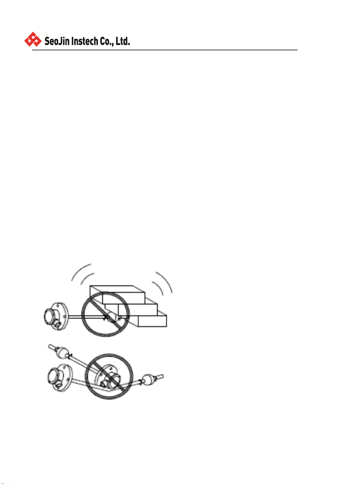
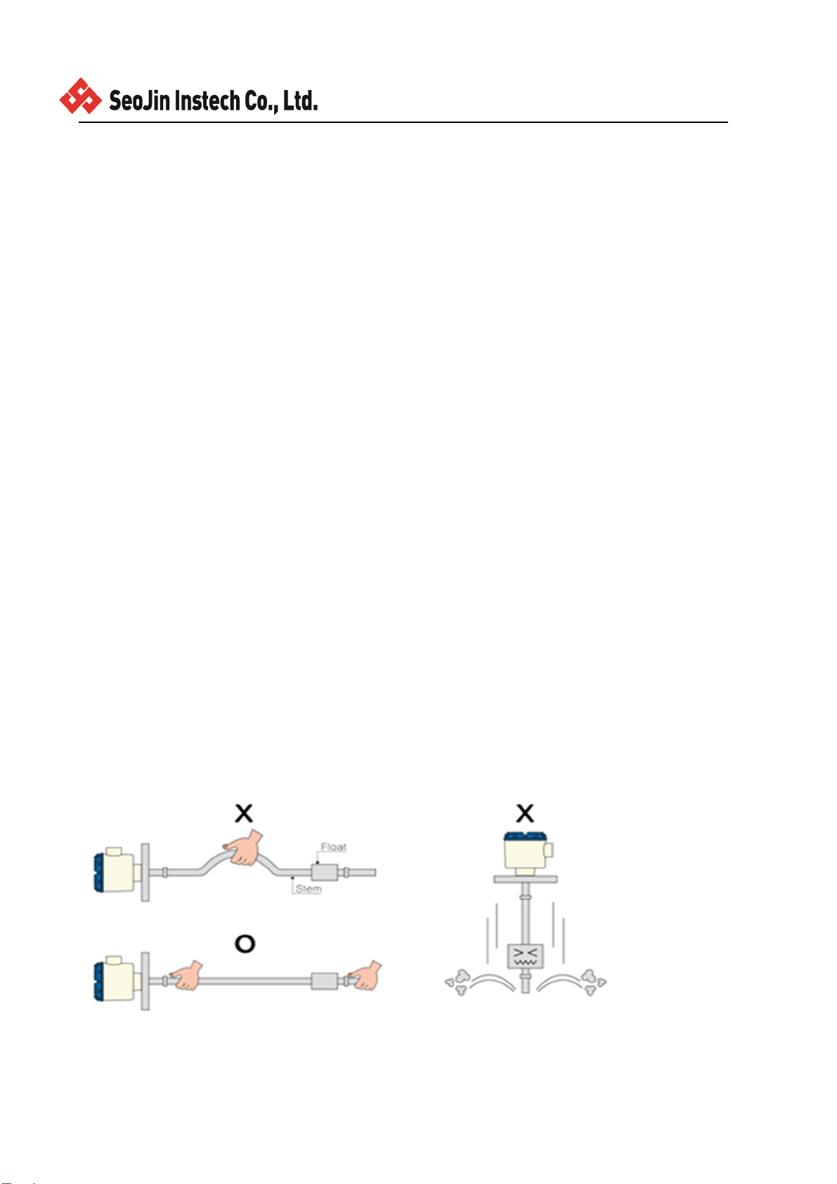
FRAGILE (Handle with care) 취급주의
1. Do not carry the Sensor with one hand.
Stem bending is sure to please carry with two hands.
Sensor를 한손으로 잡고 운반하지 마십시오.
Stem이 휨으로 반드시 두 손으로 잡고 운반하십시오.
2. Do not drop the Float.
Since the magnet inside STOPPER Float damage and leaving the Lower slowly, holding hands.
Float를 떨어뜨리지 마십시오.
Float내부에 있는 자석이 파손되고 STOPPER가 이탈되므로 손으로 잡고 서서히 내리십시오.
3. Do not throw the Sensor or shock.
Reed Switch is a failure in the internal Stem malfunction occurs.
Sensor를 던지거나 충격을 주지 마십시오.
Stem내부에 있는 Reed Switch가 파손되어 오동작이 일어납니다.
4. Do not remove the Sensor discretion.
This may cause damage and malfunction is not the A / S.
Sensor를 임의로 분리하지 마십시오.
파손 및 오동작의 원인이 되고 A/S가 안됩니다.
5. Do not use the Sensor for purposes other than level measurements.
Sensor를 레벨측정 이외의 다른 용도로 사용하지 마십시오.

Page 10/20
Rev. No.: 1
플로트 타입 레벨 트렌스미터에 대하여(ST-600)
Float Type Level Transmitter(ST-600)는 본 설치 요령서에서 제시하는 방법에 따라야만 한다.
1.INTRODUCTION 개 요
This is designed to measure liquid level by using buoyancy and magnetic force as
2-wire signal transmission.
본제품은 부력을 이용하는 액체변화량을 연속적으로 감시하는 2-Wire 방식의 Transmitter이다.
2.FEATURES 특 징
□ Wide application such municipal water, clean water, industrial water, LPG tank,
chemical tank, etc.
수돗물, 정수 공업용수, 음료수, LPG탱크, 화학탱크등에 사용가능하다.
□ Easy installation.
설치가 간편하고 가장 널리사용하는 Level Transmitter이다.
□ apply to various chemical liquids with PVC or PTFE tubing on sensing part.
검출부에 PVC, PTFE을 Tubing 처리하여 화학약품에 사용 가능하다.
□Built in arrester on circuit board to protect overvoltage and noise.
과전압 및 Noise로부터 영향을 받지 않도록 보호용 회로가 내장되어 있다.
□Constant output signal(4~20mA) even though input signal is varied (DC 15~32V)
전원 전압 DC 15~32V의 변화에도 전류는 DC4~20mA의 일정한 값이 출력된다.
3.PRINCIPLE OF OPERAION 동작원리
When the float rises and falls, the reed switches actuate by the magnetic force built in float and the
resistance is varied. The varation of resistance converts into DC 4~20mA output signal in and the level is
measured.
수위의 변화에 따라 Float가 부력에 의해 액면과 동일하게 Float 위치가 변화하면 Stem 내부의 Reed
Switch의 "ON"위치가 변화하면서 저항값에 액면 변위값과 동일한 변화를 DC4~ 20mA로 연속적으로
출력한다.
Page 11/20
Rev. No.: 1
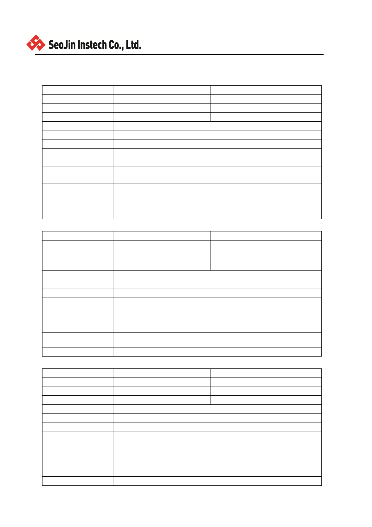
4.SPECIFICATION 사 양
Std.
ENCLOSURE Weather Proof Explosion Proof (Ex d IIC T6/ IP65)
HOUSING ADC12 ADC12
CABLE ENTRY PF1/2” Adaptor(PT1/2”, NPT3/4”…) PF1/2” Adaptor(PT1/2”, NPT3/4”…)
PROCESS TEMP. Max. 150℃ Max. 60℃
POWER SOURCE DC 24V
OUTPUT DC 4~20mA (2 Wire)
측정부압력 *FLOAT 사양 참조
측정대상 액체 전용
OVERALL LENGTH 0.5~5.9m(Max.)
WETTED PART
MATERIAL 304SS/316SS
PROCESS CONNECTION
JIS 10K 80A FLANGE, JIS 10K 100A FLANGE
JIS 10K 80A FLANGE(6t), JIS 10K 100A FLANGE(6t)
PT 2”(2” FLOAT 전용)
분해능 ±10mm
PVC
ENCLOSURE Weather Proof Explosion Proof (Ex d IIC T6/ IP65)
HOUSING ADC12 ADC12
CABLE ENTRY PF1/2” Adaptor(PT1/2”, NPT3/4”…) PF1/2” Adaptor(PT1/2”, NPT3/4”…)
PROCESS TEMP. Max. 60℃ Max. 60℃
POWER SOURCE DC 24V
OUTPUT DC 4~20mA (2 Wire)
측정부압력 Max. 2Kgf/cm²
측정대상 액체 전용 (화학약품)
OVERALL LENGTH 0.5~5m(Max.)
WETTED PART
MATERIAL PVC
PROCESS CONNECTION JIS 10K 80A FLANGE, JIS 10K 100A FLANGE
분해능 ±10mm
PTFE
ENCLOSURE Weather Proof Explosion Proof (Ex d IIC T6/ IP65)
HOUSING ADC12 ADC12
CABLE ENTRY PF1/2” Adaptor(PT1/2”, NPT3/4”…) PF1/2” Adaptor(PT1/2”, NPT3/4”…)
PROCESS TEMPE. Max. 150℃ Max. 60℃
POWER SOURCE DC 24V
OUTPUT DC 4~20mA (2 Wire)
측정부압력 Max. 0.5Kgf/cm²
측정대상 액체 전용 (내부식성)
OVERALL LENGTH 0.5~5.9m(Max.)
WETTED PARTMATERIAL PTFE
PROCESS CONNECTION JIS 10K 80A FLANGE, JIS 10K 100A FLANGE
JIS 10K 80A FLANGE(6t), JIS 10K 100A FLANGE(6t)
분해능 ±10mm
Page 12/20
Rev. No.: 1
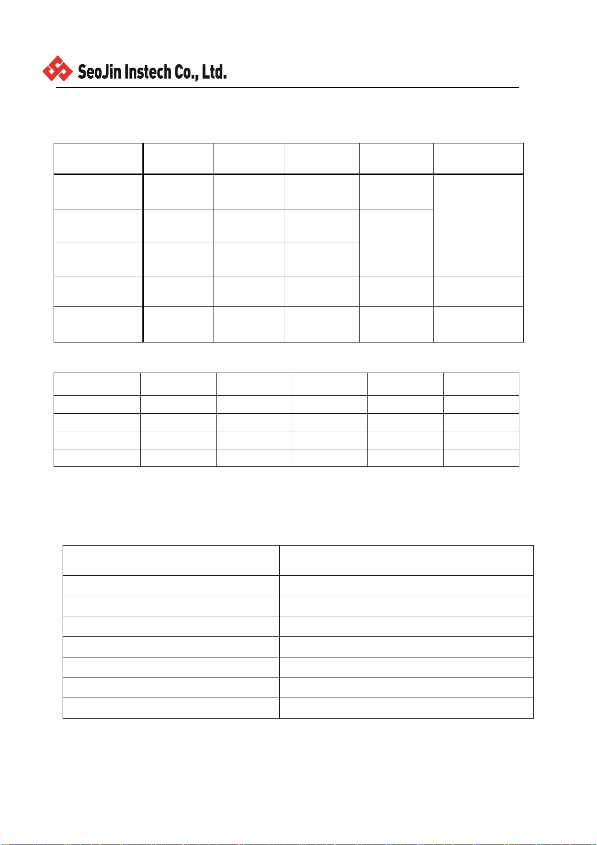
FLOAT 사양
TYPE FLOAT재질 FLOAT크기 최소적용비중
압력 온도
일반용 304SS/316SS
Ø79X90H Min.
0.85.(Std). Max. 15Kgf/cm²
-20℃~150℃
저비중용 316SS Ø102X121H
Min. 0.6
Max. 5Kgf/cm²
PT 2” 用 316SS Ø52X60H Min. 0.98
내약품용 PVC ø75*80H Min.0.62 Max. 2Kgf/cm²
-10℃~60℃
내부식성 PTFE ø78.5*99H Min.1.0 Max.
0.5Kgf/cm² -10℃~150℃
적용환경
Acid Alkaline Oil Solvent Liquid gas
304SS X △ ○ ◎ △
316SS △ ○ ○ ◎ △
PVC ○ ○ X △ X
PTFE ◎ ◎ X ○ △
*Note: ◎ = Excellent ○ = Good △ = Acceptable X = Not good
R/I Converter 사양
Item Specification
Calibration Zero/Span Volume
Supply Voltage +15Vdc ~ +32Vdc @ Typ.+24Vdc
Current Consumption 3.8mA 이하
Ambient Temperature -20℃ ~ 60℃
Current Loop Interface 2-Wire Loop Current
Output Current Range (Accuracy) 4mA ~ 20mA @ ±0.5%이하
Measurement Sensor Range Min. 1 kΩ(0.5m) Max. 10 kΩ(6m)

Page 13/20
Rev. No.: 1
5. INSTALLATION 설치방법
5-1. Caution before the installation
설치하기 전 점검사항
1)Confirm the specification of purchased products when it uses in high
temperature and pressure.
고온.고압 TANK사용시에는 구입한 제품이 적합한지 사양을 참조할 것.
2)Caution for the stem not to be bended.
Stem이 휘지 않도록 주의할 것.
3)Avoid to give any impact to sensor.
Sensor는 민갑한 제품이므로 충격을 피할 것.
4)Do not use it to high viscosity material.
부착성이 강한 액체에서는 사용하지 말 것.
5)Do not use it to the material mixed much slurry.
부유물질이 혼합된 액체에 사용하지 말 것.
6)Do not use it to the PVC float to oil.
PVC Float 는 Oil에 사용하지 말 것.
7)Do not adjust the ZERO and SPAN of ST-600R freely
(Adjust after consulting to factory).
ST-600R 의 Zero. Span볼륨을 임의로 조정하지 말 것.(Marker 상담후조정)
8)Refer to Liquid and Material Table when it applies to chemical or corrosive material.
화학 Tank.부식성이 강한 측정물에서는 측정물과 적용재질 대조표를 참조할 것.
9)Cheack the specific gravity of material(Min 0.5)
측정물의 비중을 확인할 것.(Float의 비중 S=0.65)
10)When the distance between mounting position and ceiling is lower, lower, order to
the flange separation type.
천정고가 낮은 현장에서는 Flange 분리형으로 주문할 것.
11)Install protection cover for head housing of sensor when it is installed in outside.
옥외 설치시 Head 보호용 Cover를 설치 할 것.
12)Use an arrester when the sensor is in the surge area.
옥외 설치시 낙뢰지역은 Arrester를 설치하여 Sensor를 보호할 것.(결선방법 참조)
13)Do not move the position of stopper.
Stopper의 위치를 절대로 변경해서는 안 됨.

Page 14/20
Rev. No.: 1
5-2. Installation. 설치방법.
1)Install it like as shown on fig.
그림과 같이 TANK에 설치하여 사용한다
2)Confirm the both flange.
TANK에 부착된 FLANGE가 제품규격과 맞는지 확인한다.
3)Insert the sensor into tank.
Float와 감지부를 탱크내에 삽입한다.
4)Lock the bolts, and the sensor shall be perpendicular to the surface of medium.
취부면과 수직이 되도록하고 볼트로 체결한다.
5) Connect terminal (+) and (-) of electronics to control equipment.
헤드부의 단자대의 +,-선을 제어부와 연결한다.
6. Calibration 조정방법
1)When (+) terminal of multimeter is connected to (-) of ST-600R and (-) of multimeter
to (-) of power supply. supply power voltage. (Refer to Fig 4)
전류측정시 ST-600R "-"단을 Multimeter의 “+”와 연결하고 Multimeter의 “-”단을 Power
Supply의 “-”에 연결한 후 Power를 공급한다.(Fig. 4 참조)
2)Put the float to 0% level position. and make the multimeter read DC 4mA with adjusting
ZERO volume.
Float를 하한점에 놓고 Zero 볼륨을 돌려서 Multimeter에 DC 4mA가 되도록 조정한다.
3)Put the float to 100% level position. and make the multimeter read DC 20mA with
adjusting ZERO volume.
Float를 상한점에 놓고 Span볼륨을 돌려서 Multimeter에 DC 20mA가 되도록 조정한다.
4)Repart the above 2) and 3) more than 3 times.
위의 2),3) 과정을 3회이상 반복하여 실시한다.
Page 15/20
Rev. No.: 1
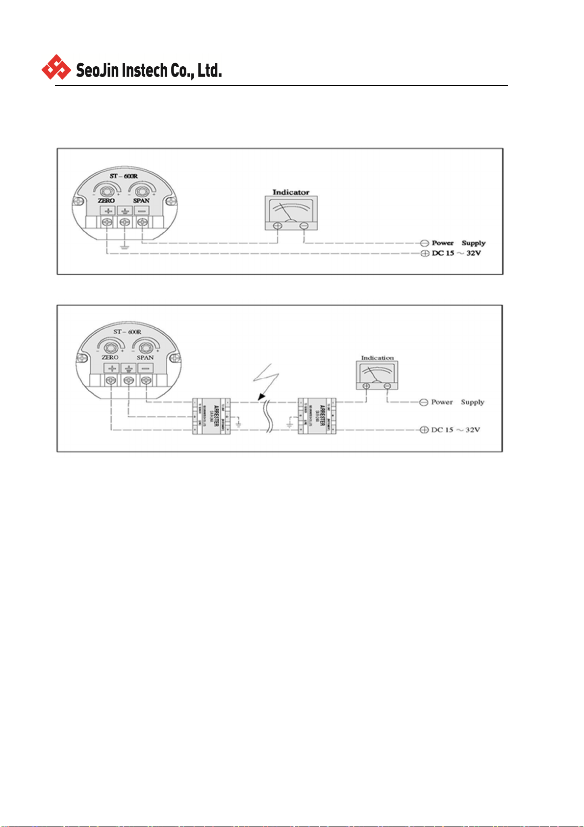
7.Wiring Connection 결선방법
7-1.Standard
7-2.낙뢰형(Lightning Protector)
8.Check point before A/S A/S전 점검사항
1)Confirm power supply (DC 15 V ~ 32 V )
전원확인(DC 15V ~ 32V)
2)Confirm output signal (DC 4mA ~ 20mA )
전류확인(DC 4 ~ 20mA)
3)Confirm stopper status
Stopper가 제위치에 단단하게 고정되어 있는가.
4)check the connected situation in connector betwween ST-600R converter and sensor.
Head부의 ST-600R와 Sensor부의 콘넥터와 연결잭 연결상태 점검.
5)Confirm the moving situation of float according to the rise and fall of material.
Float가 측정물의 변화에 따라 원활히 움직이는지 확인할 것.
6)When measuring material is in the inside of stem, dry and clean the sensor and use it again.
Stem 내부에 액체가 들어간 경우 분리세적한 후 건조하여 다시 삽입하여 사용.(Maker 상담)
7) When reed switches are broken and the current increase sharply, ask a servise to factory immediately.
Reed S/W 부분 파손시 전류가 급격히 증가하는 현상이 발생하면 즉시 A/S요청
(전류가 최대 50mA 까지 상승).
Page 16/20
Rev. No.: 1
Operating Instructions
Additional data to Explosion proof
(방폭 추가사용설명서)
ST-600 Float Type Level Transmitter
1) Introduction (소개)
1.1 PURPORE OF USE (사용 목적)
Reed switches which are built in the sensor are operated by the magnet float which moves up and down on the stem
according to the material level.
At this time, resistance value from the resistors which are connected side by side with reed switches is changed
between R1,and R10 according to the location of operating reed switch and this output value is transmitted to
convertor and it is changed to mA by the convertor and transmitted to control unit to be indicated. Do not used is
any other applications.
Please contact our sales staff if you have any special design for this product.
센서에 내장되어 리드 스위치에 측정물 레벨이 스팀에 따라 상하 이동하는 자석 플로트에 의해 작동된다.
이때, 리드와 나란히 연결되어있는 저항의 저항 값이 동작 리드 스위치의 위치와,이 출력값에 따라서 R1 및 R10 사
이에 변경치를 스위치 컨버터에 송신하며 컨버터 의해 mA로 컨버터 및 트렌스미터를 컨트롤 유닛으로 전송한다.
이 용도 이외에는 사용하지 마십시오. 이 제품의 맞춤 설계를 원하신다면 자사의 영업부로 연락 주시기 바랍니다.
2) Marking (표시)
All units have a rating label, which carries the following important information:
모든 제품에는 라벨이 붙어 있으며, 다음과 같은 내용을 포함한다
주의사항 1)HEAD내부의 단자는 반드시 EARTH 단자에 접지를 시켜야 함.
2)CABLE 인입구는 방폭성능검정 합격된 내압 슬리이브 금구식 CABLE GRAND를 사용할 것.)
KC Marking (국가통합인증마크)
규격및형식명 : ST-600
인 증 번 호 :
인 증년월일 :
인 증 규 격 : Ex d IIC T6
인 증 기 관 :
:제조년월일 :
제조회사명 : SEOJIN INSTECH CO ., LTD
www.seojin.biz

Page 17/20
Rev. No.: 1
3) Type Approval Standards
The units has KC Type Examination and Ex certificates issued by KTL has been approved to the following standards:
본 제품은 KTL 에서 발급하는 KC형식 안전인증서가 다음 표준에 의거 승인 되었습니다.
방호장치 의무안전인증 고시 (노동부고시 제2013-54호)
Reference (참조)
KS C IEC60079-0 방폭기기-제0부: 일반 요구사항
KS C IEC60079-1 방폭기기-제1부: 내압방폭구조””d””
KS C IEC60529 외곽의 방진 보호 및 방수 보호 등급(IP 코드)
4) Special Conditions For Safe Use ( 형식 승인을 위한 특수 조건 )
T6: T° Process : -20℃ to +60℃
5) WIRING 결선
5.1 PREPARATION. 준비
5.1.1 TURN OFF THE POWER. 결선하는 전선의 전원을 꺼 주십시오.
WARNING 경고
TO AVOID PERSONAL INJURY, THE POWER SOURCE SHALL BE ALWAYS TURNED OFF WHILE WIRING.
결선작업을 하기 전에 반드시 전원을 꺼 주십시오. 통전상태에서 작업시, 감전, 누전 등 인명사고의
발생 위험성이 크고 쇼트 등에 의한 화재나 기기의 파손사고에 이를 위험성이 있습니다.
CHECK FOR MISWIRING FOR THE POWER LINE. OTHERWISE, THE SENSOR WILL BE DAMAGED.
단자의 표시위치에 전압이 다른 전원을 접속하면, 센서에 과전류가 흘러 기기, 장치 등의 파손 또는
인명사고에 이를 위험이 있습니다.
CAUTION 주의
TO AVOID ELECTRICAL SHOCK AND SENSOR’S DAMAGE, GROUND TERMINAL SHALL BE ALWAYS
GROUNDED.
단자의 접지를 행하지 않으면, 만일 센서내부에서 어떤 문제가 발생하고, 전원라인의 배선이 Housing
등에 접촉됐을 경우. Housing 에 전원전압이 가해져 작업자가 접촉시 매우 위험합니다.
GROUND TERMINAL “E” SHALL BE GROUNDED AS JIS CLASS D, MAX. 100Ω
Earth 단자의 접속에 대해서 E 단자의 접지 (3 종접지, 접지저항 1000hm 이하)를 행해 주십시오.
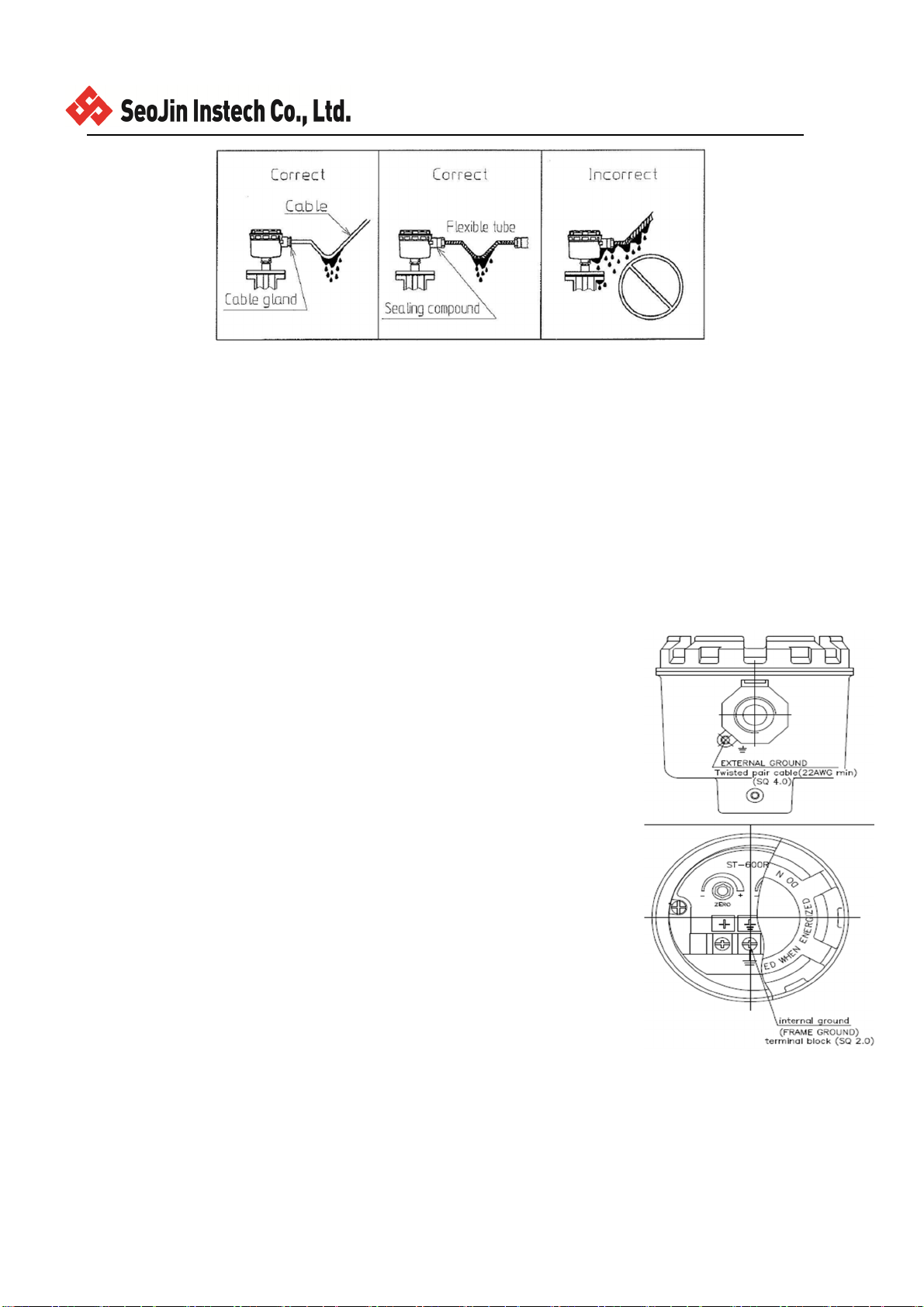
5.2 CONDUIT CONNECTION. 전원 투입구
THE ELECTRICAL WIRES ARE LED INTO THE HOUSING IN THE CABLE GLAND METHOD OR IN THE CONDUIT
METHOD. IN CASE OF THE CONDUIT METHOD, SEALING COMPOUND SHALL BE APPLIED ONTO THE SCREW OF THE
CABLE INLET TO PROTECT WATER PENETRATION. IN CASE OF THE CABLE GLAND METHOD, IT MUST BE PROPERLY
FITTED BY THE APPROPRIATE TOOLS TO PRESERVE IP AFTER WRING.
Cable을 전원 Ground에 고정하는 방법과 전선관을 Housing 어| 접속하는 방법이 있습니다.
어느 쪽도, 혹시 물이 닿을 경우 직접 Housing 에 들어가지 않도록 해 주십시오. 또한, 전선관을 접속하는
경우는 Seal 용 자재를 사용하고, 전선 Ground 에 고정하는 경우는 전용공구로 Cable 을 견고하게 고정해
주십시오. Housing 에 불순물, 먼지, 빗물 등이 들어가지 않도록 하기 위해서 입니다
Page 18/20
Rev. No.: 1
5.3 WIRING – 결선작업
WIRING SHALL BE IN ACCORDANCE WITH ALL LOCAL CODES. SINCE TERMINAL SCREWS ARE M3.5, OUR
RECOMMENDED
SOLDERLESS LUGE ARE R125-3.5 . SEE FIGURE 8-3
단자에 결선해 주십시오. SCREW의 고정은 반드시 공구를 사용해서 견고히 조여주십시오. 단자 SCREW에는 M3.5나
사를
사용하고 있기 땜눙에 압착단자는 호칭경 3.5mm 이상의 사이즈를 사용해 주십시오. 그림 8-3
6) Ground
Where required the ground connection(for example, impacted by electromagnetic wave, noise, and electromagnetic
field), the ground terminal unit or the terminal unit for external ground must be connected.
접지가 필요한 곳( 가령 전자기파, noise, 전자기 지역)에는 접지 terminal unit이나 외
부 접지용 terminal box에 연결되어야 한다
The Housing was designed for protecting against inverse polarity.
Housing은 반대 자기장 대해 보호가 되도록 설계되어야 한다.
To keep the best performance, the twisted pair cable (22AWG Min.)
is recommended.
최상의 동작을 유지하기 위해서는 2선식 케이블을 사용하여야 한다.
The displayer must be installed in the place far from the alternative current or
switching system.
디스플레이는 반드시 교류나 스위치 시스템으로부터 먼 곳에 설치되어야 한다.
The probe for instrument ground must be connected into local surface of land.
계기 접지를 위한 프로브는 땅과 연결이 되어야 한다.
Where connected with a shield cable, the shield screen must be connected to the
ground of power supply.
쉴드 케이블이 연결되는 곳에는 쉴드 스크린이 전원 공급기의 접지와 연결되어 있
어야 한다
Note
The cable impedance is defined by the maximum length possible to do the digital
communication However, Better is that using the low impedance cable. The
maximum length between both points is about 1,000m, where 250Ω of load and single twisted
cable 22AWG-207 pf/m are used.
케이블 임피던스를 디지털 커뮤니케이션에 사용하기 위해서는 가능한 최대 길이로 제한되어야 하며 이때 가장 낮은
임피던스 케이블을 사용하는 것이 좋다.
두 지점 사이의 최대 길이는 약1000m이며, 250옴과 단일 트위스트 케이블 22AWG-207 pf/m가 사용되어야 한다.

Page 19/20
Rev. No.: 1
7) Cable Selection. (케이블 선택)
When using the external earth terminal a cable crimp lug must be used.
외부 접지 터미날을 사용할 때 케이블 크림프 러그를 반드시 사용하여야 한다.
The cable lug should be located between the two M4 stainless steel flat washers, The M4 stainless steel spring
washer
must be fixed between the outer flat washer and the M4 stainless steel nut to ensure that the cable lug is secured
against loosening and twisting.
케이블 러그는 두 M4 스테인레스 평와셔 사이에 위치해야 하며, M4 스테인레스 스프링 와셔는 다른 평와셔
사이에 고정되어야 하며 M4 스테인레스 너트는 풀림과 꼬임에 대해서 안전하게 위치해야 한다.
The internal earth bonding wire ensures that a good quality earth is maintained between the flameproof chamber
casting
and the flameproof cover casting.
내부 접지 연결선은 방폭 챔버와 커버 사이에 잘 유지되어야 한다.
8)Installation Requirements(설치 필요조건)
The FLOAT TYPE LEVEL SWITCH must be installed in accordance with the latest issues of the relevant parts of the
KS C IEC60079 specifications or the equivalent IEC specifications –Selection, Installation and maintenance of
electrical
apparatus for use in potentially explosive atmospheres
(other than mining applications or explosive processing and manufacture):-
플루트 레벨 스위치는 반드시 KS C IEC60079 와 관련 IEC 사양 -선택, 설치 및 유지 보수 잠재적으로 폭발성
분위기에서 사용 하기 위해 전기 기구의 관련 부분의 최신 발행본에 따라 설치 해야 한다.
(이외: 마이닝 응용 프로그램 또는 폭발물 처리 및 제조)
KS C IEC60079-14 (위험지역의 전기설비)
KS C IEC60079-10 (폭발 위험 장소의 구분)
The installation of the units must also be in accordance with any local codes that may apply and should only be
carried out by a competent electrical engineer who has the necessary training
기기 설치는 필수교육을 받은 전기기사(현장 담당자)가 적용, 수행 해야 하는 지역 규격에 따라야 한다.
-본 내압방폭제품의 측정대상,센서부는 비폭팔성 분위기이여야 한다.
검출부(측정대상) 비폭발 유체 사용
9)Cable Glands(케이블 글랜드)
The FLOAT TYPE LEVEL SWITCH has dual cable gland entries which have an PF 3/4" entry thread as standard.
플루트 레벨 스위치의 전선관은 PF 3/4” 2 개로 되어야 한다
Only cable glands approved for Ex "d" applications can be used, which must be suitable for the type of cable being
used and also meet the requirements of the Ex "d" flameproof installation standard KS C IEC60079-14
Ex "d"에 적용 가능한 케이블 글랜트를 사용해야 하며, KS C IEC60079-14 방폭 설치의 충족요건을 만족시켜야
한다.
When only one cable entry is used the other one must be closed with an Ex ‘'d’' flameproof blanking plug, which
must be suitably approved for the installation requirements.
둘 중 하나의 케이블 글랜드만 사용할 때 나머지 하나는 방폭 요건에 맞게 플러그를 사용하여 막아 주어야 한다.
Table of contents
Other Seojin Instech Transmitter manuals

Popular Transmitter manuals by other brands


MTS Systems
MTS Systems LevelLimit Level Plus Operation manual

TeknikSat Satellite Systems
TeknikSat Satellite Systems TPF 11-2 user guide

Williams Sound
Williams Sound Hearing Helper T800 Manual and user guide

SenseAir
SenseAir aSENSE installation manual

Argos
Argos E0207TR-2 user manual

KBC
KBC eCopper EECF1-LS1-T-IN-B quick start guide


