SEON HX16 User manual

DVR Configuration (continued)
From the ConfigurationTitles and Display tab, perform
one of the following procedures, depending on your DVR
type (TH series or HX16):
TH4 or TH6 DVR:
1. Select Monitor Settings, and set the Front Default
Display option to the video channel displaying the
RVM camera feed.
Ensure Display Switch is OFF (the default setting):
2. Click Back to save changes in the menus and return
to the Titles and Display tab.
3. Set all Display options OFF, so they won’t obscure
the image on the rear vision monitor:
HX16 DVR:
1. Select Monitor Settings, and set the Rear Default
Setting option to the video channel displaying the
RVM camera feed.
Ensure Display Switch is Off (the default setting):
HX16 DVR (continued)
2. Click Back to save changes in the menus and
return to the Titles and Display tab.
3. Set all Display options Off so they won’t obscure
the image on the rear vision monitor:
4. Click Diagnostic Display.
5. Click Display None:
To complete the DVR configuration for RVM cameras:
1. Exit DVR Configuration menus.
2. Reboot the DVR and test the monitor view with
the vehicle in reverse.
3. Disconnect the diagnostic monitor and mouse.
LCD Monitor Configuration
To set up the monitor to automatically power on when the
reverse signal is triggered, see the monitor kit 080-0171
installation guide.
Monitor Mirror/
Reverse Display Mode
To set up the monitor to display in mirror mode, see the
monitor kit 080-0171 installation guide.
Warranty
For full warranty information, please visit:
http://www.seon.com/documents/Seon-Warranty.pdf.
Rear Vision Monitor Installation Guide (TH4, TH6, & HX16 DVRs)
© Seon Design Inc. | March, 2017 | All rights reserved. www.seon.com. Part Number: 700-1086 R1
Customer Service Contact Information
Toll free telephone 1-877-630-7366 Local telephone 604-941-0880
Email: service@seon.com Web: community.seon.com
(please contact Seon if you do not have access credentials)
Introduction
The RVM (Rear Vision Monitor) system for vehicles enables the driver to see the camera output on a dash-mount monitor
whenever the reverse signal is triggered.
When installed, the RVM system operates as follows:
The monitor is usually OFF (dark)
The monitor only turns ON when the vehicle is put into reverse gear (REVERSE signal is applied to the RVM)
The system is installed using a DVR camera socket, so the camera video goes through the DVR before displaying on the
monitor. RVM video, events, and alarms are recorded.
RVM Installation Components
CA or RVC303 camera (optional)
Camera power cable 060-1010
Video extension cable HE1
DVR video cable 060-0678
Camera extension cable: HE3 (75’) or HE2 (50’)
Monitor 080-0171 kit, including 080-1027 monitor
and XC-0117-B-5M, XC-0118-B-6.1M cables
Diode and wiring
DVR Expansion harness 060-1059 (TH4/TH6/HX16)
Install Guide
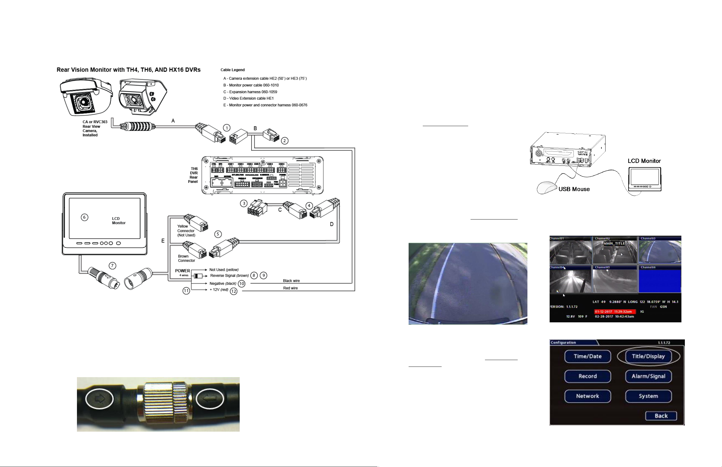
Monitor, Camera, and DVR Connections
Use the following image and steps to connect the monitor and camera to the DVR power:
1. Once the camera is installed, connect cable A to cable B.
2. Connect cable B to a camera socket on the back panel of the TH4, TH6, or HX16 DVR.
3. Connect the 2x4 micro fit connector on cable C to the EXPANSION socket on a TH4/TH6 DVR (or the
EXPANSION 1 socket on an HX16 DVR).
4. Connect the 2x3 Microfit connector on cable C to the micro fit socket on cable D.
5. Connect the 2x3 Microfit connector on cable D to the brown micro fit socket on cable E.
6. Install the monitor bracket and monitor on the dashboard, using the hardware and installation guide provided in
the monitor kit.
7. Connect the monitor output from cable D to the monitor input cable. Verify that the arrows on the connector ends
are aligned.
Monitor, Camera, and DVR Connections
(continued)
8. Connect the brown wire from cable E to the
striped end of the supplied diode.
9. Connect the unmarked end of the supplied
diode to the reverse signal input.
10. Cut off the 1x2 Microfit connector on cable B
and use the crimp to connect the black wire
from cable B to the black wire on cable E.
11. Cut the fuse from the red wire on cable E.
12. Use the crimp to connect the red wire from
cable E to the red wire from cable B.
13. See “Power On and Test”.
Power On and Test
1. Turn on accessory power to the vehicle.
2. Put the vehicle in reverse gear.
During normal operation, the monitor only
turns on when the vehicle is shifted into
reverse.
If the monitor fails to turn on when power is
applied, confirm power connections.
Disconnect and firmly reconnect the LCD
Monitor cables.
3. Configure the DVR. See “DVR Configuration”.
4. Adjust the camera view so that the bumper of
the vehicle is just visible across the bottom
edge of the monitor, as shown.
5. Refer to the camera installation guide for
details on closing and fastening the camera
once it has been aimed.
6. Configure the monitor to power on when the
reverse signal is triggered. See “LCD Monitor
Configuration”.
7. Turn off accessory power to the vehicle.
DVR Configuration
When the vehicle is in reverse gear, the camera view
appears in the RVM display. Otherwise, the monitor will
be OFF (dark).
DVR Configuration (continued)
When the RVM is integrated with a DVR, the image displayed
comes from the DVR, and may be overlaid with certain system
status text, according to the DVR settings.
NOTE: IP (Internet Protocol) camera views cannot be
displayed on the monitor.
To configure the DVR to properly display the RVM camera
information:
1. On the DVR, connect a diagnostic monitor to the front
Video Out RCA jack, and plug in a USB mouse.
2. In the camera views, identify the RVM camera feed
and note the associated camera title (you will need it
to set the configuration menus in the next step).
“Channel 03” displays the RVM camera in the TH6
Live View shown below:
3. Right-click and select Configuration, then select
Title/Display:
Other manuals for HX16
1
This manual suits for next models
2
Other SEON Automobile Accessories manuals

Popular Automobile Accessories manuals by other brands


ULTIMATE SPEED
ULTIMATE SPEED 279746 Assembly and Safety Advice

SSV Works
SSV Works DF-F65 manual

ULTIMATE SPEED
ULTIMATE SPEED CARBON Assembly and Safety Advice

Witter
Witter F174 Fitting instructions

WeatherTech
WeatherTech No-Drill installation instructions

TAUBENREUTHER
TAUBENREUTHER 1-336050 Installation instruction