SEON RVM-TLHD User manual
Rear Vision System (TL-HD DVR) Installation Guide
© Seon Design Inc. | July 2014 | All rights reserved. www.seon.com. Part Number: 700-1033 R003
Introduction
The Rear Vision System (RVM-TLHD) for vehicles enables the driver to see the camera output on a dash mount monitor whenever the
reverse signal is triggered.
When installed, the Rear Vision System operates as follows:
• The monitor will usually be OFF (dark)
The monitor will only turn ON when the bus is put into reverse gear (REVERSE signal is applied to the RVM)
The RVM-TLHD is installed using a TL-HD DVR camera socket, so the camera video goes through the DVR before displaying on the
monitor. RVM-TLHD video, events, and alarms are recorded.
RVS Installation Components
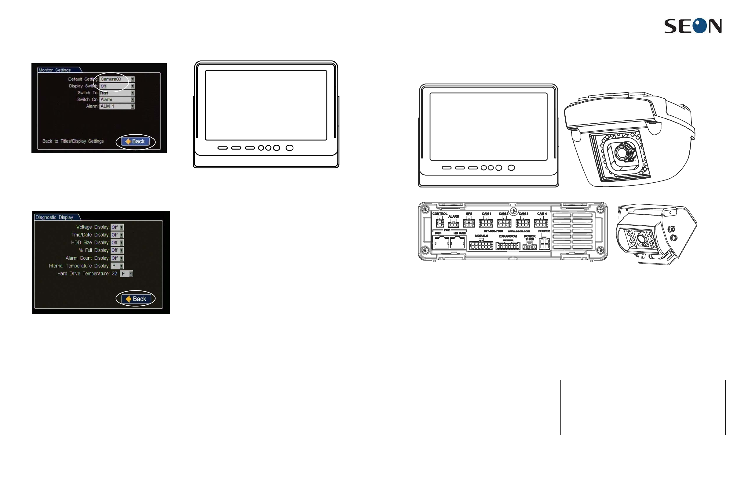
4 Select Monitor Settings, and set the Default Display DVR
menu option to the video channel displaying the RVS camera
video.
The display switch should be OFF (default setting).
5 Click BACK to save changes in the menus.
6 Click Diagnostic Display and, in the menu, turn off the
diagnostic information (Voltage, HDD etc.) so it will not
display on the rear view monitor.
The Status, Version, Speed, and camera name overlay text
will still display.
7 Exit the DVR menu.
8 Reboot the DVR and test the monitor view with the vehicle in
reverse.
9 Disconnect the diagnostic monitor and mouse.
LCD Monitor Configuration
To setup the monitor to automatically power on when the reverse
signal is triggered, see the monitor kit 080-0171 installation guide.
Monitor Mirror/Reverse Display
Mode
To setup the monitor to display in mirror mode, see the monitor kit
080-0171 installation guide.
Warranty
Seon Design Inc. (Seon) warrants the cameras and components
listed below against defects in workmanship and materials provided
that such defects appear or are discovered within the respective
periods specified below and provided further that the purchaser of
such products notifies Seon of such defects within thirty (30) days
of the appearance or discovery of such defects:
• Three (3) years from date of purchase, parts and repair
labor on all Cameras
• Three (3) years from date of purchase, parts and repair
labor on the Explorer® Premier, DX, TX, EX, MX, and
Trooper® TL series mobile DVR Systems
• Three (3) years from date of purchase, parts and repair
labor on all storage media (including hard drives)
• One (1) year from date of purchase, parts and repair labor
on the Smart Reach® Wireless systems and other Wireless
products
• One (1) year from date of purchase, parts and repair labor
on the VML Controller, Student Tracking RFID reader, and
other vMax Live Plus hardware products
• One (1) year from date of purchase, parts and repair labor
on all other products and accessories
All service/replacement parts and repairs are warranted for a period
of 90 days. For full warranty information, go to www.seon.com.
Seon Contact Information
• Toll free telephone 1-877-630-7366
• Local telephone 604-941-0880
• Web: www.seon.com
CA or RVC303 camera (optional) Camera power cable 060-1010
Camera extension cable, HE3 (75’) or HE2 (50’) DVR video cable 060-0678
Monitor 080-0171 Diode and wiring
Monitor power and connector cable 060-0676 Install guide
TL-HD DVR Expansion harness 060-1014
*700-1033*
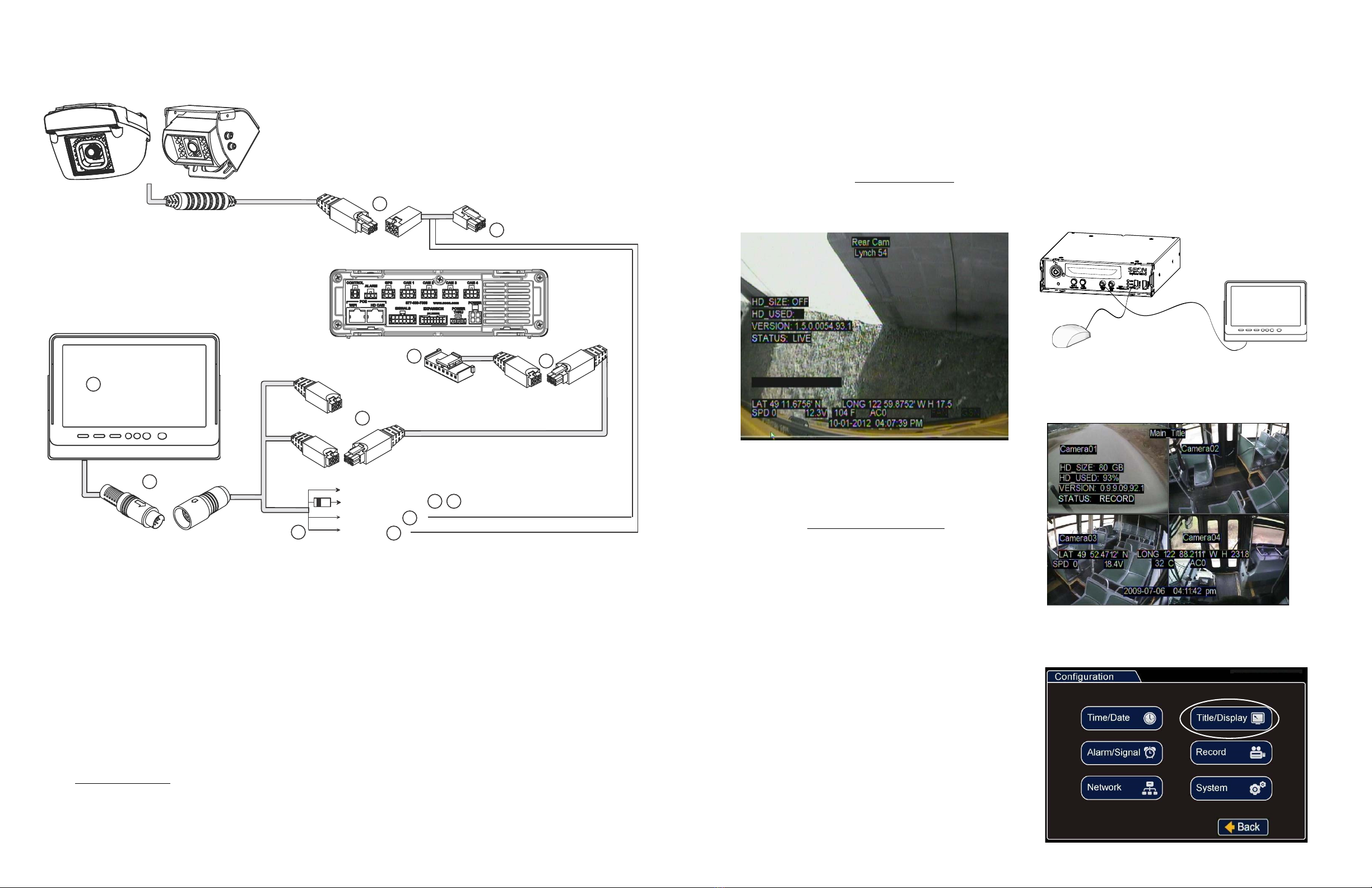
Monitor Camera and DVR Connections
Use the following image and steps to connect the monitor and camera to the DVR power.
1 Once the camera is installed, connect cable A to cable B.
2 Connect cable B to a camera socket on the back panel of the TL-HD DVR.
3 Connect the 8x1 Sherlock connector on cable C to the EXPANSION socket on the TL-HD DVR.
4 Connect the 2x3 Microfit connector on cable C to the micro fit socket on cable D.
5 Connect the 2x3 Microfit connector on cable D to the brown micro fit socket on cable E.
6 Install the monitor bracket and monitor on the dashboard, using the hardware and installation guide provided in the monitor kit.
7 Connect the monitor output to cable E.
8 Connect the brown wire from cable E to the striped end of the supplied diode.
9 Connect the unmarked end of the supplied diode to the reverse signal input.
10 Cut off the 1x2 Microfit connector on cable B and use the crimp to connect the black wire from cable B to the black wire on cable E.
11 Cut the fuse from the red wire on cable E.
12 Use the crimp to connect the red wire from cable E to the red wire from cable B.
13 See “Power On and Test”.
Rear Vision System With TL-HD DVR
TL-HD
DVR
Rear
Panel
2
3
7
8
4 wires
+ 12V (red)
Negative (black)
POWER
9
10
Not Used (yellow)
Cable Legend
A
1
D
E
LCD
Monitor
Brown
Connector
Yellow
Connector
(Not Used)
4
B
Black wire
Red wire
12
C
A - Camera extension cable HE2 (50`) or HE3 (75`)
B - Camera power cable 060-1010
C - Expansion cable 060-1014
D - Extension cable HE1
E - Monitor power and connector cable 060-0676
5
6
11
CA or RVC303
Rear View
Camera,
Installed
Reverse Signal (brown)
Power On and Test
1 Turn on accessory power to the vehicle.
2 Set the vehicle to reverse.
In normal operation, the monitor will only turn on when the
bus is put into reverse.
If the monitor fails to turn on when power is applied, confirm
power connections. Disconnect and firmly reconnect the LCD
Monitor cables.
3 Configure the DVR. See “DVR Configuration”.
4 Adjust the camera view so that the bumper of the bus is just
visible across the bottom edge of the monitor.
5 Refer to the camera installation guide for details on closing
and fastening the camera once it has been aimed.
6 Configure the monitor to power on when the reverse signal is
triggered. See “LCD Monitor Configuration”.
7 Turn off accessory power to the vehicle.
DVR Configuration
When the reverse signal is on, the camera view displays in the
RVS monitor. Otherwise, the monitor will be OFF (dark).
NOTE
: HD camera views cannot be displayed on the monitor.
When the RVS is integrated with a TL-HD DVR, the image
displayed on the RVS Monitor comes from the DVR and will
display information according to the DVR settings.
Use the following steps to configure the DVR to properly display
the RVS camera information.
1 On the DVR, plug in a diagnostic monitor into the front Video
Out RCA jack and plug in a USB mouse.
2 From the camera views that display, identify the RVS camera
feed and the camera view title for use in the configuration
menus.
3 Right-click and select Configuration, then select Title/Display.
LCD Monitor
MX-HDON
L
Y
USB Mouse
Other SEON Automobile Accessories manuals

Popular Automobile Accessories manuals by other brands


ULTIMATE SPEED
ULTIMATE SPEED 279746 Assembly and Safety Advice

SSV Works
SSV Works DF-F65 manual

ULTIMATE SPEED
ULTIMATE SPEED CARBON Assembly and Safety Advice

Witter
Witter F174 Fitting instructions

WeatherTech
WeatherTech No-Drill installation instructions

TAUBENREUTHER
TAUBENREUTHER 1-336050 Installation instruction