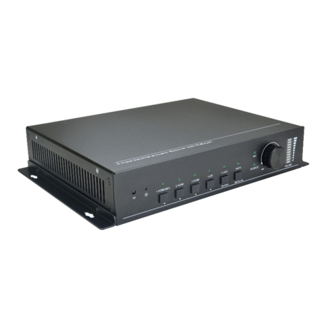
SEON NRPOE08-KIT User manual

© Seon Design Inc. | August 2017 | All rights reserved. www.seon.com Part Number: 700-1096 R1
8-Port PoE Expansion Kit - Quick Install Guide
Kit Contents (NRPOE08-KIT)
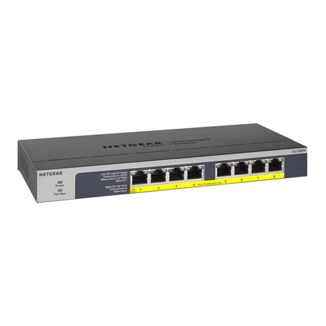
• 8-Port PoE switch (NRPOE08)
• Includes 2 x wall mount brackets and 6 x athead M3
screws
• PoE Hardware Kit (020-1039)
• 4 x No. 10 self-drilling mounting screws - 3/4”length
(600-0038)
• CAT5 cable - 3’ length (085-0082)
• 16-gauge black ground wire - 10’length (410-0033G)
• 16-gauge red power wire - 3’length (410-0034G)
• 16-14 butt splice (444-1025)
• Relay Kit (020-1040)
• Relay (450-1001)
• Relay socket harness (060-1082)
• 15A fuse and holder (420-1000)
• 2 x 16-16 butt splices (444-0071G)
• No. 10 mounting screw - 3/4”length (600-0038)
This kit supports up to 8 external IP cameras (16 IP cameras
using the optional second PoE switch) operating with the Seon
NX16 Hybrid NVR in default NVR mode.
For camera conguration details and NX16 NVR product
documentation, visit community.seon.com. If you do not have
access credentials, please contact Seon Customer Service.
Important: NX16 DVR mode is not compatible with
this expansion kit. For more information, see the NX16
documentation, or contact Seon Customer Service.
Location Avoid exposure to water drips and installation
locations with heat or moisture. Route wiring
and cables away from sharp edges that might
damage insulation. Avoid sharp bends in cables.
Surface Do not mount the PoE switch to a plastic panel
or other surface subject to constant vibration.
Clearance Allow sucient clearance above the PoE switch
for access to the terminal block wiring, and
in front of the PoE switch for the camera and
uplink connections.
Ventilation To prevent overheating, ensure airow
around the PoE switch is unrestricted - include
minimum 3/4” clearance for the top and bottom
venting holes.
Installation Requirements
Step 1: Mount the PoE Switch
Replace Rail Mount with Wall Mount Brackets
First, remove the DIN rail plate and install the supplied wall
mount brackets:
1. Rotate the device to the far side and locate the DIN rail
mounting plate.
2. Remove the 3 screws securing the rail mounting plate to
the rear panel of the PoE switch.
3. Align the wall mounting brackets on the rear sides. The
screw holes on the device and the mounting brackets
must be aligned.
4. Secure the wall mount brackets with the 6 M3 screws:
Installation Diagram

Step 1: Mount the PoE Switch (continued)
Choose a vertical wall or a horizontal shelf, ideally close to the
NVR:
1. Locate the installation site, and place the PoE switch
against the wall or shelf.
2. Use the 4 No. 10 x 3/4” self-drilling screws to attach the
PoE switch to the mounting surface with the wall mount
brackets.
Step 2: Install the Relay
Mount the Relay Socket Harness
Choose a location with enough clearance to allow snapping
the relay into the mounted socket.
1. Fasten the relay to the mounting surface with the No. 10 x
3/4” screw (600-0038).
2. Snap the relay into the relay socket.
1. Plug the 2x1 Microt connector from the relay harness into
the CONTROL port on the NX16 NVR rear panel.
2. Connect the 20-foot red 16-gauge y wire from the relay
harness to the 15A fuse and holder (420-000).
a. Wire the other side of the 15A fuse/holder to an
unswitched power source (12 to 24 VDC).
3. Connect the 3-foot red 16-gauge y wire from the relay
harness to the PoE switch V1+ terminal.
Wire the Relay
1. Turn on the vehicle ignition.
2. The P1 (power on) LED on the front panel of the PoE
switch should show solid green. Otherwise, check all
connections, or contact Seon Support.
Step 3: Wire the PoE Switch
1. Connect the 10-foot black 16-gauge wire (410-0033G)
from the PoE switch V1- terminal to the vehicle battery
negative/ground.
2. Remove the port cover from one of the PoE switch uplink
ports (number 9or 10).
3. Connect the 3-foot CAT5 cable (085-0082) from the PoE
switch uplink port to the NX16 HD CAM EXPANSION
input.
4. Connect IP cameras to port numbers 1through 8on the
PoE switch, as required. For instructions on setting up IP
cameras, see the NX16 Hybrid NVR Quick Install Guide (NVR
mode), part #700-1095.
Tip: Leave unused port covers in place to prevent uid
or dust from entering the device.
Step 3: Wire the PoE Switch (continued)
Step 4: Power on and Test
WARNING - Power Budget: Each PoE switch can supply
a maximum of 50 Watts@12V or 60 Watts@24V to the
connected cameras. If you are unsure if an installation
will exceed this limit, contact Seon Service.
Tip: The PoE switch relies on the NVR’s CONTROL signal
for power On/O. See the NX16 documentation for
details.
Tip: A faint pink glow visible below the power LEDs is
part of normal operation.
Add a Second PoE Switch (optional)
NX16 installations supporting more than 12 IP cameras require
a second PoE switch (NRPOE08P - includes a PoE hardware kit
020-1039). A second relay is not required.
1. Mount the second PoE switch (follow the Installation
Requirements, and Step 1 in this Guide).
2. Connect a 3-foot red 16-gauge power wire (410-0034G) to
the V1+ terminal on the second PoE switch.
a. Use the 16-14 butt splice (444-1025) to splice the power
wires for both PoE switches (410-0034G) with the 3-foot
red 16-gauge y wire from the relay harness (see step 3
in “Wire the Relay”).
3. Connect the 10-foot black 16-gauge wire (410-0033G) from
the V1- terminal on the second PoE switch to the vehicle
battery negative/ground.
4. Connect the 3-foot CAT5 cable (085-0082) from an uplink
port on the second PoE switch to an uplink port on the rst
PoE switch.
5. Connect IP cameras to port numbers 1through 8on the
second PoE switch, as required.
6. Turn on the vehicle ignition to power on and test, as
described in Step 4 for the rst PoE switch procedure,
above.
Tip: If the installation includes a second PoE switch, do
not make the connection to the V1+ terminal yet: you will
need to splice in power for the second PoE switch. See
Step 2 in“Add a Second PoE Switch” .
