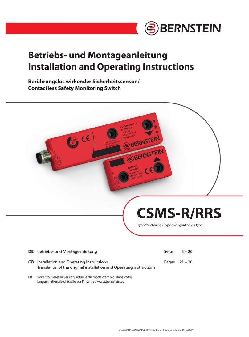
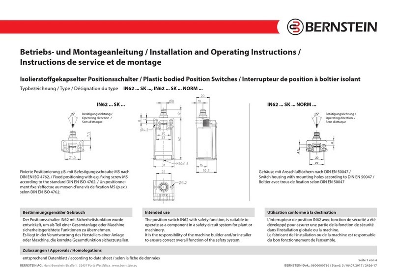
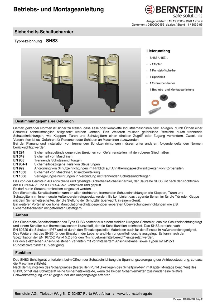
BERNSTEIN Ti2 Series User manual

BERNSTEIN AG . Hans-Bernstein-Straße 1 . 32457 Porta Westfalica . www.bernstein.eu Seite 1 von 8
0800000852, 2761-17 / Issue date: 2017-12-04
Betriebs- und Montageanleitung / Installation and Operating Instructions / Instructions de service et de montage
BERNSTEIN AG . Hans-Bernstein-Straße 1 . 32457 Porta Westfalica . www.bernstein.eu BERNSTEIN-Dok.: 0800000852 / Stand: 1 / 2017-12-04 / 2761-17 Seite 1 von 8
BERNSTEIN AG . Hans-Bernstein-Straße 1 . 32457 Porta Westfalica . www.bernstein.eu BERNSTEIN-Dok.: 0800000852 / Stand: 3 / 2017-12-04 / 2071-17 Seite 1 von 16
www.bernstein.eu
Betriebs- und Montageanleitung/
Installation and Operating Instructions/
Instructions de service et de montage
Contact
International Headquarters
BERNSTEIN AG
Hans-Bernstein-Straße 1
32457 Porta Westfalica
Fon+49 571 793-0
Fax +49 571 793-555
www.bernstein.eu
China
BERNSTEIN Safe Solutions
(Taicang) Co., Ltd.
Fon+86 512 81608180
Fax +86 512 81608181
info@bernstein-safesolutions.cn
Hungary
BERNSTEIN Kft.
Fon+36 1 4342295
Fax +36 1 4342299
Denmark
BERNSTEIN A/S
Fon+45 7020 0522
Fax +45 7020 0177
France
BERNSTEIN S.A.R.L.
Fon+33 1 64 66 32 50
Fax +33 1 64 66 10 02
info@fr.bernstein.eu
Italy
BERNSTEIN S.r.l.
Fon+39 035 4549037
Fax +39 035 4549647
United Kingdom
BERNSTEIN Ltd
Fon+44 1922 744999
Fax +44 1922 457555
Austria
BERNSTEIN GmbH
Fon+43 2256 62070-0
Fax +43 2256 62618
Switzerland
BERNSTEIN (Schweiz) AG
Fon+41 44 775 71-71
Fax +41 44 775 71-72
Betriebs- und Montageanleitung / Installation and Operating Instructions / Instructions de service et de montage
BERNSTEIN AG . Hans-Bernstein-Straße 1. 32457 Porta Westfalica . www.bernstein.eu BERNSTEIN-Dok.: 0800000852 / Stand: 1 / 2017-12-04 / 2761-17 Seite 1 von 8
Isolierstoffgekapselter Grenztaster /
Insulation-enclosed limit switch /
Interrupteur de position à boîtier isolant
Baureihe Ti2 / Series Ti2 / Série Ti2
Ti2

BERNSTEIN AG . Hans-Bernstein-Straße 1. 32457 Porta Westfalica . www.bernstein.eu Seite 2 von 8
Betriebs- und Montageanleitung / Installation and Operating Instructions / Instructions de service et de montage
BERNSTEIN AG . Hans-Bernstein-Straße 1. 32457 Porta Westfalica . www.bernstein.eu BERNSTEIN-Dok.: 0800000852 / Stand: 1 / 2017-12-04 / 2761-17 Seite 2 von 8
Bestimmungsgemäßer Gebrauch/
Intended use/
Utilisation conforme à la destination
1
Die isolierstoffgekapselten Grenztaster Ti2 werden zur Abtas-
tung von Bewegungsvorgängen eingesetzt, die durch Steuer-
kurven, Lineale, Profile usw. auf die Betätigungseinrichtungen
einwirken.
Beim Gebrauch an trennenden Schutzeinrichtungen, als
Positionsschalter mit Sicherheitsfunktion dürfen nur Grenz-
taster eingesetzt werden, auf deren Etikett ein entsprechen-
des Symbol (�) ist.
Ti2 Insulation-enclosed limit switchs are used to detect rotatio-
nal, linear, angular, (etc.) moving objects when they meet the
devices actuation head.
When being used as a safety limit switch, only limit switches
that bear a corresponding symbol (�) on the label can be
used.
Ti2 Interrupteurs de position à boîtier isolant pour la
détection de mouvements qui agissent sur les dispositifs
d‘actionnement via des cames de commande, règles, profilés,
etc.
Pour l‘utilisation sur des dispositifs de protection séparateurs,
seuls les fins de course avec un symbole correspondant (�)
sur leur étiquette peuvent être utilisés comme interrupteurs
de position avec fonction de sécurité.
D – Deutsch GB – English FR – Français
Identizierung durch Typbezeichnung/
Type designation and identication/
Identication par la désignation
2
1 Schalterfamilie I88
1 2345
Ti2 - U1Z Riw 90GR
2 Kontaktbestückung des Einbauschalters (2 bis 5-stellig)
U1Z 1) = Wechsler
2) 1 Öffner/ 1 Schließer
SU1Z 1) = Wechsler
3) 1 Öffner/ 1 Schließer
A2Z 1) = Öffner
2) 2 Öffner
SA2Z 1) = Öffner
3) 2 Öffner
E2 = Schließer
2) 2 Schließer
SE2 = Schließer
3) 2 Schließer
1) Z = Zwangsönung
Mit Betätigungseinrichtung FF, AV, AD oder AF entfällt Z.
Dann wird nur U1, UV1, SU1, A2 oder SA2 angegeben.
2) Schleichschaltglied,
3) Sprungschaltglied
1 Switch group I88
2 Contact configuration of the built-in switch (2 to 5 digits)
U1Z 1) = Changeover contact 2) 1 NC/ 1 NO
SU1Z 1) = Changeover contact 3) 1 NC/ 1 NO
A2Z 1) = NC contact 2) 2 NC
SA2Z 1) = NC contact 3) 2 NC
E2 = NO contact 2) 2 NO
SE2 = NO contact 3) 2 NO
1) Z = Positive opening operation
With actuator FF, AV, AD or AF no Z. Then only U1, UV1, SU1,
A2 or SA2 is specied.
1) Slow-action,
2) Snap-action
1 Famille de commutateurs I88
2 Configuration des contacts de l‘interrupteur encastrable
(2 à 5 chiffres)
U1Z 1) = inverseur
2) 1 NF/ 1 NO
SU1Z 1) = inverseur
3) 1 NF/ 1 NO
A2Z 1) = ouverture
2) 2 NF
SA2Z 1) = ouverture
3) 2 NF
E2 = fermeture
2) 2 NO
SE2 = fermeture
3) 2 NO
1) Z = Panoeuvre positive d’ouverture - Avec un orientation de
l‘actionneur FF, AV, AD ou AF on invalide Z. Ensuite seul les
congurations U1, UV1, SU1, A2 ou SA2 sont attribués.
2) à rupture lente, 3) à rupture brusque

BERNSTEIN AG . Hans-Bernstein-Straße 1 . 32457 Porta Westfalica . www.bernstein.eu Seite 3 von 8
Betriebs- und Montageanleitung / Installation and Operating Instructions / Instructions de service et de montage
BERNSTEIN AG . Hans-Bernstein-Straße 1 . 32457 Porta Westfalica . www.bernstein.eu BERNSTEIN-Dok.: 0800000852 / Stand: 1 / 2017-12-04 / 2761-17 Seite 3 von 8
3 Betätigungseinrichtungen (2 bis 4-stellig)
W = Stößel, Dichtung außen
K = Knopf
ST = Stössel, verstellbar
RIWL = Rollenstößel lang
RIWK = Rollenstößel kurz
HW = Hebel
HLW = Hebel lang
DGHW = Drehgelenk, Hebel
DGKW = Drehgelenk, Kniehebel
KNW = Kniehebel
KGW = Kipphebelglied
FF 4) = Federfühler
AH = Achshebel
AHS = Achshebel, Sternklemmung
AD 4) = Achshebel, Draht
ADK 4) = Achshebel, Draht, Kunststoffstab
AV 4) = Achshebel, verstellbar
AF 4) = Achshebel, Feder
KS = getrennter Betätiger
VKS = Verriegelung Klappe senkrecht
VKW = Verriegelung Klappe waagerecht
4) Die Option führt dazu, dass das Endprodukt keine Zwangs-
trennung an den Kontakten hat. Im Block 2„Kontaktbestü-
ckung“ entfällt dann das„Z“ (für Zwangstrennung) aus der
Bezeichnung der Schaltfunktion. Es wird nur U1, SU1, A2 oder
SA2 angegeben.
3 Actuators (2 to 4 digits)
W = Plunger, external seal
K = Button
ST = Adjustable plunger
RIWL = Roller, long
RIWK = Roller, short
HW = Lever
HLW = Lever, long
DGHW = Pivot joint, lever
DGKW = Pivot joint, cranked lever
KNW = Cranked lever
KGW = Cranked lever link
Spring feeler 4) = Federfühler
AH = Spindle-mounted lever
AHS = Spindle-mounted lever, star clamping
AD 4) = Spindle-mounted lever, wire
ADK 4) = Turret head, adjustable rod, plastic rod
AV 4) = Spindle-mounted lever, adjustable
AF 4) = Spindle-mounted lever, spring
KS = Seperate actuator
VKS = Guard locking vertically
VKW = Guard locking horizontally
4) This option leads to the fact that the final product is without
automatic disconnection of the contacts. In this case, for
block 2„contact configuration“, there is no„Z“ (for positive
opening action) in the designation of the switch function.
Only U1, SU1, A2 or SA2 are indicated.
3 Dispositifs d‘actionnement (2 à 4 chiffres)
W = Poussoir, Capuchon externe
K = Bouton
ST = Poussoir, réglable
RIWL = Galet, haut
RIWK = Galet, bas
HW = Levier
HLW = Levier, long
DGHW = Levier pivotant réglable
DGKW = Levier pivotant réglable inversé
KNW = Levier escamotable
KGW = Auxiliaire à levier articulé
FF 4) = Tige à ressort
AH = Levier d’axe
AHS = Levier d’axe, réglage en étoile
AD 4) = Levier d’axe, fil
ADK 4) = Levier d‘axe, fil, tige en plastique
AV 4) = Levier d’axe, réglable
AF 4) = Levier d’axe, ressort
KS = Actionneur séparé
VKS = Verrouillage portillon, verticalement
VKW = Verrouillage portillon, horizontalement
4) Cette option implique que le produit final est sans séparation
forcée des contacts. Dans ce cas, en bloc 2 «équipement des
contacts», il n‘y a pas de «Z» (séparation forcée) dans la dési-
gnation de la fonction de commutation. Seuls U1, SU1, A2 ou
SA2 sont mentionnés.

BERNSTEIN AG . Hans-Bernstein-Straße 1. 32457 Porta Westfalica . www.bernstein.eu Seite 4 von 8
Betriebs- und Montageanleitung / Installation and Operating Instructions / Instructions de service et de montage
BERNSTEIN AG . Hans-Bernstein-Straße 1. 32457 Porta Westfalica . www.bernstein.eu BERNSTEIN-Dok.: 0800000852 / Stand: 1 / 2017-12-04 / 2761-17 Seite 4 von 8
4 Position Betätigungseinrichtung (4 bis 5-stellig)
Frei = Betätigungseinrichtung nicht gedreht
90GR = 90 Grad gedrehte Betätigungseinrichtung
180GR = 180 Grad gedrehte Betätigungseinrichtung
270GR = 270 Grad gedrehte Betätigungseinrichtung
5 Sonderheit (Beispiele)
Frei = Keine Sonderheit
M12 = M12 Anschlussstecker
HVG = Goldkontakte
M16 = Gehäuse mit M16 Kabeleinführung
Rast = Gehäuse mit Rastfunktion
SW = Schwarzes Schaltergehäuse
IP67 = Gehäuse mit Schutzart IP67
NPT = Gehäuse mit Reduzierring auf„National Pipe
Thread“, (amerikanische Gewindegröße)
VS = verstärkte Schaltkraft
LS = leichte Schaltkraft
180GR90GR
Betätigungseinrichtung nicht gedreht /
Actuating device not rotated /
Dispositif d‘actionnement non orienté
4 Position actuating device (4 to 5 digits)
Blank = Actuating device not rotated
90GR = 90 Degrees actuating device rotated
180GR = 180 Degrees actuating device rotated
270GR = 270 Degrees actuating device rotated
5 Option (examples)
Blank = No option
M12 = M12 Connector
HVG = Gold contacts
M16 = Enclosure with M16 cable entry
Rast = Enclosure with latching function
SW = Black switch housing
IP67 = Enclosure with protection class IP67
NPT = Enclosure with reduction ring to„National
Pipe Thread“, (American thread size)
VS = increased switching force
LS = light switching force
4 Position dispositif d‘actionnement (4 à 5 chiffres)
Vide = dispositif d‘actionnement non orienté
90GR = dispositif d‘actionnement orienté à 90 degrés
180GR = dispositif d‘actionnement orienté à 180 degrés
270GR = dispositif d‘actionnement orienté à 270 degrés
5 Option (exemples)
Vide = pas d‘option
M12 = Connecteur M12
HVG = Contacts dorés
M16 = Boîtier avec entrée de câble M16
Rast = Boîtier avec maintien du verrouillage
SW = Boîtier d‘interrupteur noir
IP67 = Boîtier avec degré de protection IP67
NPT = Boîtier avec bague de réduction à «National
Pipe Thread», (taille du filetage américaine)
VS = Force de commutation augmentée
LS = Force de commutation faible
270GR

BERNSTEIN AG . Hans-Bernstein-Straße 1 . 32457 Porta Westfalica . www.bernstein.eu Seite 5 von 8
Betriebs- und Montageanleitung / Installation and Operating Instructions / Instructions de service et de montage
BERNSTEIN AG . Hans-Bernstein-Straße 1 . 32457 Porta Westfalica . www.bernstein.eu BERNSTEIN-Dok.: 0800000852 / Stand: 1 / 2017-12-04 / 2761-17 Seite 5 von 8
Montage/
Installation/
Montage
3
•
Ein unsachgemäßer Einbau oder Manipulation des Sicher-
heitsschalters führt zum Verlust der Personenschutzfunk-
tion und kann zu schweren oder tödlichen Verletzungen
führen.
•
Die Montage und der elektrische Anschluss dürfen nur von
autorisiertem Fachpersonal durchgeführt werden.
•
Der Anwendungsbereich/ die Montageposition für das
Schaltgerät ist so zu wählen, dass die Funktionssicherheit
durch äußere Einflüsse wie z. B. Verschmutzungen (Späne,
Staub, Flüssigkeiten, ...), nicht beeinträchtigt wird.
•
Der Schalter darf nicht als Anschlag verwendet werden.
•
Werden Zuhaltungen/ Positionsschalter hintereinander
geschaltet, dann wird der Performance Level nach
DINEN13849-1 reduziert. Der Grund ist eine verringerte
Fehlererkennung.
•
Das Gesamtkonzept der Steuerung, in welche der Positions-
schalter eingebunden wird, ist nach DIN EN ISO 13849-2 zu
validieren bzw. nach DIN EN 62061 zu bewerten.
•
Die Höhenlage des Verwendungsorts darf nicht mehr als
2000 m über NN betragen.
•
An improper installation or manipulation of the safety
switch will render the personal protection function use
less and can cause serious injury or accidental death.
•
The installation and electrical connection must only be
carried out by authorized personnel.
•
The fields of application / mounting position for the switching
device shall be chosen such that the functional safety will not
be affected by external influences such as dirt (chips, dust
and liquids...).
•
The switch shall not be used as a mechanical stop.
•
The performance level in accordance with DIN EN 13849-1 is
reduced if latching devices/position switches are connected
in series. This is due the fact that fault recognition is reduced.
•
The overall control concept, into which the position switch
has been integrated, must be validated in accordance with
DIN EN ISO 13849-2 or evaluated according to DINEN62061.
•
The altitude of the site of installation does not exceed 2000 m.
•
Un montage ou une manipulation non correcte de l’inter-
rupteur de sécurité entraîne la perte de la fonction de
protection des personnes et peut conduire à des blessures
graves voire mortelles.
•
Le montage et le raccordement électrique doivent être
effectués exclusivement par un personnel habilité.
•
Le champ d‘application / la position de montage pour le
dispositif de commutation est à choisir de telle manière que
la sécurité de fonctionnement ne soit pas affecté par des
perturbations extérieurs ou des pollutions telles que (copeaux,
poussières, liquides, ...).
•
Ne pas utiliser l’interrupteur comme butée.
•
Si des verrouillages / interrupteurs de position sont commutés
les uns après les autres, le niveau de performance est réduit
selon la norme DIN EN 13849-1. Cela est dû à une reconnais-
sance réduite des erreurs.
•
Le concept global du contrôle, dans lequel l´interrupteur de
position devrait être intégré, faudrait être validé conformé
ment aux normes de DIN EN ISO 13849-2 ou bien l‘evaluation
selon DIN EN 62061.
•
L‘altitude du site d‘installation ne dépasse pas 2000 m.
Der Positionsschalter ist auf einer ebenen und biegesteifen
Fläche zu befestigen. Hierbei ist darauf zu achten, dass auch
im Fehlerfall, ein Verschieben des Positionsschalters mit Sicher-
heitsfunktion verhindert wird. Um den Schalter gegen unbe-
fugtes Lösen zu sichern, wird die Verwendung von Einweg-
Sicherheitsschrauben empfohlen. Bei der Installation eines
Schaltgerätes mit Würgenippel muss zur Zugentlastung eine
feste Verlegung des Anschlusskabels erfolgen.
The position switch should be mounted on a flat and rigid
surface. It should be ensured that even during a fault condition,
the position switch with safety function remains in its fixed
location. The use of safety fixing screws is recommended.
When installing a switching device with twist nipple, a fixed
installation of the connection cable is absolutely necessary
for strain relief.
L’interrupteur de position doit être fixé sur une face plane et
rigide à la flexion. Il faut veiller à ce que l’interrupteur de position
avec fonction de sécurité ne se déplace pas en cas de défaut.
Afin d’assurer l’interrupteur contre le desserrage non autorisé,
il est recommandé d’utiliser des vis de sécurité à usage unique.
Lors du câblage avec raccord fileté, le câble doit être installé de
manière fixe afin d’assurer une décharge de traction.
Safety InstructionsSicherheitshinweise Consignes de sécuritè
Die Montage und der Betrieb müssen nach der Norm
DINENISO14119, ENISO12100 und EN953 erfolgen.
Insbesondere sind die Anforderungender DINENISO14119,
Abschnitt 7„Konstruktion zum Verringern von Umgehungs-
möglichkeiten“, zu berücksichtigen.
Installation and operation must be carried out in
accordance with DIN EN ISO 14119, ENISO12100 and
EN953. The requirements of the DIN EN ISO 14119, section7
“construction for preventing any possibility of circum-
vention”, in particular must be taken into account.
Le montage et l’opération doivent être effectués
conformément à la norme DIN EN ISO 14119,
ENISO12100 et EN953. Il convient de tenir compte des
exigences de DINENISO14119, section 7 «construction
pour empêcher toute possibilité de contournement».

BERNSTEIN AG . Hans-Bernstein-Straße 1. 32457 Porta Westfalica . www.bernstein.eu Seite 6 von 8
Betriebs- und Montageanleitung / Installation and Operating Instructions / Instructions de service et de montage
BERNSTEIN AG . Hans-Bernstein-Straße 1. 32457 Porta Westfalica . www.bernstein.eu BERNSTEIN-Dok.: 0800000852 / Stand: 1 / 2017-12-04 / 2761-17 Seite 6 von 8
Elektrischer Anschluss Electrical connection Raccordement électrique
Der elektrische Anschluss darf nur durch autorisiertes Fach-
personal erfolgen. Stellen Sie sicher, dass der Schalter vor
Öffnen des Deckels spannungsfrei ist.
Das Öffnen des Deckels erfolgt mittels Schraubendreher. Gege-
benenfalls ist vorher eine Deckelschraube zu lösen.
Das Anzugsdrehmoment der elektrischen Kontakte mit M3,5
Schraubanschlüssen ist 0,8 Nm.
Das Anzugsdrehmoment der elektrischen Kontakte mit M3
Schraubanschlüssen ist 0,6 Nm.
Der Anschluss muss als Litze mit Aderendhülse oder eindrähtig
mit den Leiterquerschnitten 0,5 – 1,5mm² erfolgen.
Das Anzugsdrehmoment einer Deckelschraube ist 0,3 bis
0,4Nm. Eine Deckelschraube mit Einwegkopf ist mit 1,1 - 1,2
Nm anzuziehen.
Electrical connection should only be carried out by authorised
technical personnel. Make sure that the switch is de-energised
before opening the cover.
The cover is opened by using a flat blade screwdriver, If
optional cover screw fitted, please undo before attempting to
open.
The tightening torque of electrical contacts with M3.5 threaded
connections is 0.8 Nm.
The tightening torque of electrical contacts with M3 threaded
connections is 0.6 Nm.
The connection must be made as a braided wire with ferrule or
as a single wire with a conductor cross-section of 0.5-1.5 mm².
The tightening torque of a cover screw is 0.3 to 0.4 Nm. A cover
secured with a tamper-proof screw head, must be tightened
within 1,1 - 1,2 Nm.
Uniquement un personnel spécialisé agréé est autorisé à
procéder au branchement électrique. Assurez-vous avant
l‘ouverture du couvercle que l‘interrupteur est hors tension.
Utiliser un tournevis pour ouvrir le couvercle. Le cas échéant,
déserrer une vis du couvercle au préalable.
Le couple de serrage des contacts électriques avec raccords à
vis M3,5 est de 0,8 Nm.
Le couple de serrage des contacts électriques avec raccords à
vis M3 est de 0,6Nm.
Le raccordement doit se faire comme toron avec embout ou en
un fil avec les sections de conducteur 0,5 – 1,5 mm².
Le couple de serrage d‘une vis de couvercle est 0,3 à 0,4 Nm.
Une vis de couvercle avec tête jetable doit être serrée à 1,1 -
1,2 Nm.

BERNSTEIN AG . Hans-Bernstein-Straße 1 . 32457 Porta Westfalica . www.bernstein.eu Seite 7 von 8
Betriebs- und Montageanleitung / Installation and Operating Instructions / Instructions de service et de montage
BERNSTEIN AG . Hans-Bernstein-Straße 1 . 32457 Porta Westfalica . www.bernstein.eu BERNSTEIN-Dok.: 0800000852 / Stand: 1 / 2017-12-04 / 2761-17 Seite 7 von 8
Betätigungseinrichtung anpassen/
Installation of the actuator/
Installation de l´actionneur
4
Nach jeder Veränderung (z. B. Umsetzen, Montage, ... )
ist eine Funktionsprüfung durchzuführen.
After each change (for ex. positioning, assembly, ... ) carry
out a function test.
Après chaque modification (telle que changement, assem-
blage, ...), il faudra effectuer une vérification du fonction-
nement.
Stellen Sie sicher, dass der Schalter vor jeder Umbaumaßnahme
spannungsfrei ist und nur durch autorisiertes Fachpersonal
erfolgt.
Umsetzen der Betätigungseinrichtung
Die Betätigungseinrichtung kann in 90 Grad Schritten umge-
setzt werden. Dazu die 4 Schrauben, die die Einrichtung mit
dem Gehäuse verbinden, herausschrauben. Die Einrichtung in
die gewünschte Position bringen und die 4 Schrauben mit
0,3–0,4 Nm anziehen. Darauf achten, dass keine Dichtelemente
(z. B. O-Ring) verloren gehen oder beschädigt werden.
Achshebel, Winkel ändern
Bei den Ausführungen mit Betätigungseinrichtung AH, AHS
und AV kann der Winkel des Hebels in 15 °-Stufen eingestellt
werden. Hierzu die Befestigungsmutter oder -schraube lösen,
die Hebelstellung verändern und die Befestigungsmutter oder
-schraube mit 2,2 Nm* anziehen.
Achshebel, Rollenseite ändern
Je nach Betätigungseinrichtung lässt sich die Seite, auf der sich
die Rolle befindet ändern, indem man den Hebel mit Rolle um-
dreht. Die Befestigungsmutter oder -schraube muß mit 2,2Nm*
angezogen werden.
Achshebel, Betätigungshöhe ändern
Bei der Ausführung AV kann die Position der Rolle in der Höhe
individuell festgelegt werden. Mutter bzw. Schraube, die den
Hebel fixiert lösen, Position der Rolle einstellen und anschlie-
ßend die Befestigungsmutter oder -schraube mit 2,2 Nm
anziehen.
* Bei Varianten mit Sperrkantscheibe (bei AH, AHS) ist die
Befestigungsmutter oder -schraube mit 2,5 Nm anzuziehen.
Ensure that the switch is de-energised before each conversion
and that it is only carried out by authorised, qualified personnel.
Positioning the actuating device
The actuating device can be positioned in 90 degree steps.
To do this, unscrew the 4 screws that connect the device to the
housing. Move the device into the desired position and tighten
the 4 screws with 0.3–0.4Nm. Be careful not to lose or damage
any sealing elements (e.g. O-ring).
Change the angle of the axis lever
The angle of the lever can be adjusted (in steps of 15 °) on the
versions with actuation devices AH, AHS and AV. To do this,
loosen the mounting nut or screw, change the lever position
and tighten the mounting nut or screw to 2.2 Nm*.
Changing the axis lever on the roller side
Depending on the actuating device, the side on which the roller
is located can be changed by turning the lever with the roller.
The mounting nut or screw must be tightened with 2.2 Nm*.
Changing the actuation height of the axis lever
In the AV version, the height of the roller can be adjusted indi-
vidually. Loosen the nut or screw that holds the lever in place,
adjust the position of the roller and then tighten the mounting
nut or screw to 2.2Nm.
* For versions with a spacer disk (for AH, AHS), the fixing nut or
fixing screw must be tightened to 2,5 Nm.
Assurez-vous avant toute modification que l‘interrupteur est
hors tension et que le travail est effectué par un spécialiste
agréé.
Activation du dispositif d‘actionnement
Le dispositif d‘actionnement peut être orienté par intervalles
de 90 degrés. Pour cela, dévisser les 4 vis fixant le dispositif
au boîtier. Mettre le dispositif dans la position souhaitée et
visser les 4 vis à 0,3–0,4 Nm. Veiller à ce qu‘aucun élément
d‘étanchéité (par ex. le joint torique) ne soit perdu ou
endommagé.
Levier d‘axe, modifier l‘angle
Pour les modèles avec un dispositif d‘actionnement AH, AHS et
AV, l‘angle du levier peut être réglé en par paliers de 15°. Pour
cela, défaire l‘écrou ou la vis de fixation, modifier la position du
levier et visser l‘écrou ou la vis de fixation à 2,2Nm*.
Levier d‘axe, modifier le côté du galet
Avec certains dispositifs d‘actionnement, il est possible de
modifier le côté sur lequel se trouve le galet en retournant le
levier avec galet. L‘écrou ou la vis de fixation doit être vissé(e)
à 2,2Nm*.
Levier d‘axe, modifier la hauteur d‘actionnement
Pour le modèle AV, il est possible de fixer particulièrement la
hauteur du galet. Défaire l‘écrou ou la vis qui fixe le levier, régler
la position du galet, puis visser l‘écrou ou la vis de fixation à
2,2Nm.
* Dans les variantes avec rondelle (AH, AHS), l‘écrou ou vis de
fixation doivent être serrés à 2,5 Nm.
Vor Inbetriebnahme Prior to operation Avant la mise en service

BERNSTEIN AG . Hans-Bernstein-Straße 1. 32457 Porta Westfalica . www.bernstein.eu Seite 8 von 8
Betriebs- und Montageanleitung / Installation and Operating Instructions / Instructions de service et de montage
BERNSTEIN AG . Hans-Bernstein-Straße 1. 32457 Porta Westfalica . www.bernstein.eu BERNSTEIN-Dok.: 0800000852 / Stand: 1 / 2017-12-04 / 2761-17 Seite 8 von 8
13
42
Technische Daten
Produktspezifische Eigenschaften sowie weitere technische
Daten entnehmen Sie bitte dem Technischen Datenblatt.
Weiterführende Informationen erhalten Sie unter
www.bernstein.eu.
Haftungsausschluss
Bei Verletzung der Anweisungen (bestimmungsgemäßer
Gebrauch, Sicherheitshinweise, Montage und Anschluss durch
geschultes Personal, Prüfung auf sichere Funktion) erlischt die
Herstellerhaftung.
Liability disclaimer
By breach of the given instructions (concerning the intended
use, the safety instructions, the installation and connection
through qualified personnel and the testing of the safety
function) manufacturer’s liability expires.
Exclusion de la responsabilité
La responsabilité du fabricant est annulée si les instructions ne
sont pas respectées (emploi conforme à l’utilisation prévue,
consignes de sécurité, montage et branchement effectués par
un personnel ayant reçu la formation nécessaire, contrôle de la
sécurité de fonctionnement).
Technical data
Please refer to the technical data sheet for product-specific
characteristics and other technical data.
For further information please visit www.bernstein.eu.
Caractéristiques techniques
Pour les caractéristiques du produit et les données techniques,
veuillez vous référer à la fiche technique.
Rendez-vous sur www.bernstein.eu pour des informations
complémentaires.
Haftungsausschluss – Technische Daten /
Liability disclaimer – Technical Data /
Exclusion de la responsabilitè – Caractéristiques techniques
5
Reihenfolge beim Anschrauben beachten (über Kreuz
anziehen). Observe the sequence when screwing on (tighten crosswise). Respecter l‘ordre lors de la xation de la vis (visser en croix).
Hinweis Notice Remarque
Die deutsche Sprachfassung ist die Originalbetriebs- und Mon-
tageanleitung. Bei anderen Sprachen handelt es sich um die
Übersetzung der Originalbetriebs- und Montageanleitung.
The original operating and installation instructions are the
German language version. Other languages are a translation of
the original operating and installation instructions.
La version allemande est la langue d’origine des instructions
de service et de montage. Les autres langues ne sont qu’une
traduction des instructions de service et de montage en langue
allemande.
Other BERNSTEIN Switch manuals
