Seppi MIDIPIERRE Operating instructions

1
DEUTSCHESPAÑOL ITALIANO ENGLISHFRANCIS
OPERATING AND MAINTENANCE MANUAL
STONE CRUSHERS & FORESTRY TILLERS
MIDIPIERRE, MIDIPIERRE dt, MIDISOIL dt, MULTIFORST, STARSOIL, SUPERSOIL, MAXISOIL
ENGLISH
MIDIPIERRE
STARSOIL SUPERSOIL MAXISOIL
MIDIPIERRE dt MIDISOIL dt MULTIFORST

3
2
Overall view
hood opening cylinders
hood
compacting roller or
grader blade
(optionals)
gearbox
3-point linkage
PTO shafts or
extensions
skids
gearboxes
or belts

3
2
DEUTSCHESPAÑOL ITALIANO ENGLISHFRANCIS
TABLE OF CONTENTS
Machine identification data
AttachmentsIntroduction
Congratulations on your choice! For over 75 years the
goal of SEPPI M. S.p.A. has been to guarantee high
quality products which will have a long working life,
and manufacture them to meet customers' require-
ments.
In manufacturing its machines, SEPPI M. S.p.A.
uses the best materials and technology. However, to
make the most of the designers’ best efforts to make
functional, reliable machines with valid safety devices,
you must read carefully the instructions in this user’s
manual and in the safety instructions (an integral part
of the manual). When the machine is treated and kept
with care, it limits all types of problems and saves you
time and money.
In case this information is insufficient, our staff and
your dealer will always be available for any further
clarification.
PLEASE CAREFULLY READ THE PRESENT MANU-
AL, THE USER'S MANUAL OF THE PTO SHAFT AND
RULES FOR THE USE OF
SHAFT CONES.
THE PRESENT MANUAL MUST BE KEPT TOGETHER
WITH THE USER'S MANUAL OF THE PTO SHAFT AND
THE RULES FOR THE USE OF SHAFT CONES.
- EC declaration of conformity
- Use and maintenance manual of PTO shaft
(if supplied upon request)
- Rules for the use of shaft cones
- Spare parts list
- Technical commercial documentation
This manual contains all functional, technical char-
acteristics and performance features for the machine
regarding it’s “intended – expected use”. It also con-
tains all operating and maintenance instructions. This
manual has been written for:
- operators responsible for transport and handling
- operators using the machine
- maintenance personnel.
A person must be responsible for keeping the doc-
umentation provided with the machine in a suitable
place so that it is always in good condition and availa-
ble for consultation.
If this manual is lost or deteriorated, request a
replacement copy from the manufacturer; always indi-
cate the serial number (indicated in the manual) when
making your request.
NOTE: the manufacturer must be promptly notified of
any changes to the site of destination and/or owner-
ship or location of the machine.
1. PRELIMINARY INFORMATION
1.1 Symbols: meaning and use 4
1.2 Collaboration with the user 4
1.3 Compliance with standards 4
1.4 Manufacturer's responsibility and warranty 4
2. SAFETY AND ACCIDENT PREVENTION
2.1 Operator qualification 5
2.2 Introduction to safety at work 5
2.3 Safety rules and residual risks 5
2.4 Stickers and safety labelling 9
3. TECHNICAL INFORMATION
3.1 Intended use 10
3.2 Models 10
3.3 Safety devices 11
3.4 Technical data
4. HANDLING AND COMMISSIONING
4.1 Handling, lifting and unloading 12
4.2 Commissioning 12
4.3 Adjustments 15
5. OPERATION AND USE
5.1 Checks prior to work 16
5.2 Tractor selection 16
5.3 Starting the cooling system 17
5.4 Start-up and processing 17
5.5 Safety distances 18
6. MAINTENANCE
6.1 Belt tension check and adjustment 18
6.2 Lubrication 19
6.3 Oil leaks 20
6.4 Safety devices and information 20
6.5 Replacing tools 20
6.6 Replacing anti-wear frame 22
6.7 Checking screws 22
6.8 Troubleshooting 22
6.9 Disabling 23
7 SPARE PARTS 23
8 CONTROL REGISTER 23
9 DISMANTLING, SCRAPPING AND WASTE
DISPOSAL
23 “CE” marking: affixed to machine structure
To fill out upon delivery of the machine:
Manufacturer: SEPPI M. S.p.A.
Zona Artigianale 1
39052 CALDARO (BZ) –
ITALY
Manual code: Stone crusher Rev 2 of
1.09.2014
Machine:
Model:
Serial number:
Year of manufacture:

5
4
1. PRELIMINARY INFORMATION
This manual introduces to the use of the following
models of stone crushers: MIDIPIERRE, MIDIP-
IERRE dt, MIDISOIL dt, MULTIFORST, STARSOIL,
SUPERSOIL, MAXISOIL.
The list is not binding as it can also be used for
other models (given the type of machine, operat-
ing modes and adjustments are almost identical).
Models with a different type of adjustment are
noted separately. The models are listed according
to their size (or power required to be driven).
It also contains all the essential
instructions for safety and adjustments,
maintenance and troubleshooting.
Directive 2006/42/EC
EN ISO 12100 Safety of machinery
- Basic concepts, general principles for design
- Technical principles and specifications
EN ISO 4413 Safety of machinery
- Hydraulic fluid power. General rules and safety
requirements for systems and their components
EN ISO 4254-1 Agricultural, forestry, landscap-
ing and garden machinery
- Common safety requirements
- Part 1: agricultural self-propelled, mounted,
semi-mounted and trailed machines
EN ISO 4254-5 Agricultural machinery
- Power-driven soil-working machines
- Safety
Danger
Indicates a danger with the
risk of injury, even serious.
Failure to comply with the
instructions marked with this
symbol can lead to a situation
of serious danger for the
safety of the operator and/or
of exposed persons!
Strictly abide by that indi-
cated!
Caution
Represents a warning to pay
attention to possible deteri-
oration of the machine or to
another personal object of
the operator.
Important warning to which
you must pay the utmost
attention!
Warning
Indicates a warning regard-
ing key functions or
useful information.
The warranty does not apply in case of any type
of direct or indirect breakage or accidents to
the appliance and/or objects and/or persons not
attributable to defects already present when
placed on the market and which were not easily
recognisable by the user.
In this manual, some symbols are used to draw
the reader’s attention and to emphasise some
particularly important aspects.
The manual reflects the state of the art at the
moment the machine was placed on the market.
If the manufacturer deems it timely to send the
user an addition to the manual, this document
must be kept on hand with the manual.
Contact the manufacturer for further information
and also if you have any suggestions for improve-
ment which could help make the present manual
better meet user's needs.
If the first owner transfers the machine, he
should inform the manufacturer about the ad-
dress of the new owner so that
he can receive notifications and/or essential
updates.
1.1 Symbols: meaning and use 1.2 Collaboration with the user
1.3 Compliance with standards
1.4 Manufacturer's responsibility and warranty
The machine was designed and built in compli-
ance with the safety-related standards of industri-
al machinery in force when placed on the market.
In particular, the following legislative stand-
The customer is the holder of rights according to appli-
cable national legislation governing the sale of goods.
This warranty does not place these rights in jeopardy
should they be more extensive than that indicated here.
ards and harmonised standards were taken into
account:

5
4
DEUTSCHESPAÑOL ITALIANO ENGLISHFRANCIS
2. SAFETY AND ACCIDENT PREVENTION
The warranty never covers maintenance service
expenses unless foreseen in the contract (sched-
uled assistance, good operation warranty, etc.).
- Improper operations. For example:
failure to comply with all the indications con-
tained in this manual. This category includes
problems caused by negligence or errors by the
operator (such as using the machine contrary
to national laws, inadequate maintenance, use
by untrained personnel, failure to comply with
instructions, especially those in the "Safety"
chapter or marked with the "DANGER" symbol,
etc.);
using the machine despite having noticed evident
defects.
- Treatment of unsuitable materials (due to size
and/or type).
- Transport and/or handling.
- Environmental or climatic conditions. For exam-
ple rain, lightning, freezing, contamination.
- Corrosion and standard wear (which objects such
as hammers, belts, paint, etc. are subject to)
- Modifications or adjustments not specifically
allowed in the manual or without written consent
of the manufacturer.
- Use of non-original spare parts or accessories or
not authorised by the manufacturer.
- use of the machine contrary to national laws;
- failure to comply with the instructions;
- unauthorised changes to the machine;
- use of the machine by untrained or
unfit personnel (see point 2.1);
- Use of different types of spare parts (with differ-
ent features)
Also remember that, regardless of whether or not
a problem occurs, the warranty becomes null and
void in case of:
Therefore damage caused by the following is not included:
Do not use the appliance be-
fore having read or illustrated
the instruction manual. The
attachments are an integral
part of the manual.
2.1 Operator qualification
This appliance was designed to be used by a max-
imum of one professional operator on the tractor,
guaranteeing the following requirements: The person in charge of delivery to the end
customer must watch over the tractor hitching
process.
Thereby he must have read the manual before
entrusting the customer with the machine and
understand its contents, also relating to laws of
the country of use, and taking on full responsibili-
ty for the operation.
- be older then 18 years of age and in good physi-
cal and mental health;
- have a sufficient level of general and technical
knowledge to understand the contents of this
manual, to correctly interpret diagrams and
pictograms and to perform the allowed mainte-
nance;
-know this manual and its attachments, especially
regarding safety information;
- know the main technological, hygienic and
accident prevention standards and, if foreseen
by law, periodically attend training courses on
specific risks;
- know the risks and what to do in case of emer-
gencies, where to find the personal protective
equipment and how to use it correctly;
- be sensitive to safety-related issues, promptly
reporting any failures.
2.2 Introduction to safety at work
2.3 Safety rules and residual risks
Safety was the primary objective
when designing the machine; nonetheless opera-
tors' carelessness can invalidate the efforts of the
designers.
The machine was designed and built with the
intention of eliminating as many risks as possible
for the user.
However, considering the variability of the situ-
ations as well as foreseeable misuse, there are
residual risks which cannot be eliminated, either
for functional purposes or because they do not
depend directly on the machine.
Information on residual risks is aimed at guaran-
teeing that the user take the protective measures
which, for example, can include adopting safe
work procedures, restricting tasks to trained and
authorised operators, etc.
We shall describe some of these risks, highlight-
ing some, and not necessarily all, important rec-
ommendations for each one: further recommen-
dations (or these) are included in other chapters,
either general or related to a specific operation.
Thereby SEPPI M. S.p.A. will not be held liable in
case of:

7
6
Always - reduce speed or interrupt work whenever gripping to the ground is reduced (strong slope, presence of mud, snow, etc.). Pay the utmost attention when chang-
ing direction on slopes or slippery ground.
Always - be extremely cautious when the work area is not completely visible (inspect the area before working). Only work with natural light and good visibility.
Always - check that the weight which the tractor can lift is compatible with that of the equipment. Conduct tests to check the driving stability of the tractor. With the
machine connected and lifted from the ground at least 20% of the weight of the tractor must rest on the front axle or, for machines mounted at the side, 10% on each
wheel on the side opposite the stone crusher.
Always - before detaching machine from the tractor, engage the parking brake and make sure the tool is stable.
Always - make sure that passages on roads, through gates, etc. are sufficiently wide so that the tractor with the applied tool can pass.
1) Risk of losing adherence (with the possibility of the tractor rolling over)
To reduce the likelihood of risk to a minimum, strictly follow these instructions:
Never - abandon the tractor's driver seat and approach the machine before the blade holder rotor is stopped and the tractor stopped in safe conditions. Caution! The
rotor can continue to rotate for 5 minutes after the PTO has stopped due to inertia.
Never - work with the protections of the transmissions not intact or not in perfect working order. Immediately restore all protections and safety devices when damaged
or worn (stone guards, PTO shaft protection, etc.).
Always - prevent third parties from approaching the machine while running or when the tractor is moving.
Always - disengage the PTO and stop the engine, removing the key from the dashboard before performing any adjustment or maintenance.
3) Risk of conveying due to pulleys, belts or chains
To reduce the likelihood of risk to a minimum, strictly follow these instructions:
Never - abandon the tractor's driver seat and approach the machine before the blade holder rotor is stopped and the tractor stopped in safe conditions. Caution! The
rotor can continue to rotate for 5 minutes after the PTO has stopped due to inertia.
Always - prevent third parties from approaching the machine while running or when the tractor is moving.
Always - disengage the PTO and stop the engine, removing the key from the dashboard before performing any adjustment or maintenance.
Always - check that the PTO shaft is mounted correctly (safety pin in its seat); appropriate protections on PTO shaft, tool side and tractor side; free wheel device mount-
ed on the tool side (see PTO shaft safety manual).
2) Risk of conveying due to rotary shafts
To reduce the likelihood of risk to a minimum, strictly follow these instructions:
Never - transit or stop in front of machines in motion and/or with rotor running.
Always - disengage the PTO, close the hood, stop the engine, and remove the key from the dashboard before performing any adjustment or maintenance.
4) Risk of crushing or shearing limbs between moving parts
To reduce the likelihood of risk to a minimum, strictly follow these instructions:

7
6
DEUTSCHESPAÑOL ITALIANO ENGLISHFRANCIS
Never - use the machine to mulch pieces of metal (iron wire, etc.) or non-vegetal material (risk of injury, pollution, intoxication, etc.) or work against unknown obstacles
without first having inspected the area to identify their nature.
Never - start the machine with the 3-point linkage lifted and the machine beyond 10 cm above the ground.
Never - keep the PTO engaged during transport or transfer.
Never - work with the protections of the transmissions not intact or not in perfect working order.
Never - work without suitable personal protective equipment: gloves, protective goggles, work suits and, if necessary, mask for the respiratory tract.
Never - abandon the tractor's driver seat and approach the machine before the blade holder rotor is stopped and the tractor stopped in safe conditions. Caution! The
rotor can continue to rotate for 5 minutes after the PTO has stopped due to inertia.
Always - inspect the ground and remove foreign material before working (steel and metal cables, other dangerous materials such as glass, powders and liquids in
containers, etc.)
Always - prevent third parties from approaching the machine while running or when the tractor is moving. The operator must always guarantee a safety distance even
towards houses, roads or animals.
Always - on roads or in public areas, use the danger/work in progress signs foreseen by standards in force, placing them at a sufficient distance from the machine.
5) Risk of injury due to ejection of objects
To reduce the likelihood of risk to a minimum, strictly follow these instructions:
Never - work underneath the lifted machine without adequate safety supports.
Never - transit or pass or stop in front of machines in motion and/or with rotor running.
Never - use the machine to fell trees without mounting a guard frame, available as an option, as the trees could fall on the tractor.
Never - allow children to play near the tool.
Always - on roads or in public areas, use the danger/work in progress signs foreseen by standards in force, placing them at a sufficient distance from the machine.
Always - make sure there are no persons or obstacles before making manoeuvres.
7) Risk of impact, crushing or falling
To reduce the likelihood of risk to a minimum, strictly follow these instructions:
Never - work without suitable personal protective equipment: gloves, protective goggles, work suit.
Never - check for oil leaks with bare hands, but always use a sheet of paper.
Never - disconnect quick or fixed couplings of pressurised pipes before having switched the tractor off and discharged the pipes by activating the tractor distributors
with the engine off and the appliance on the ground.
6) Risk of injury by pressurised fluids
To reduce the likelihood of risk to a minimum, strictly follow these instructions:

9
8
Never - use the machine without knowing its technical features and without supervision by qualified personnel.
Never - use the machine with the tractor's PTO speed different than that recommended and/or indicated on the machine.
Never - work beyond the PTO shaft limit angles indicated by the manufacturer of the PTO shaft (see PTO shaft manual).
Never - continue working despite foreign material stuck on the blade holder rotor (such as iron wire, nylon, twine, etc.).
Never - use the machine to mulch pieces of metal (iron wire, etc.) or non-vegetal material (risk of injury, pollution, intoxication, etc.) or work against unknown obstacles
without first having inspected the area to identify their nature.
Never - switch off the engine of the tractor without first having disengaged the PTO.
Never - use the machine with the rotor off-balance. Always restore damaged or lost tools to immediately eliminate dangerous vibrations.
Never - use different types of spare parts as they might not have the required features.
Never - leave the machine outdoors subject to the elements.
Never - use the machine to fell trees without mounting a guard frame, available as an option, as the trees could fall on the tractor.
Always - approach the material to be mulched slowly without causing blows.
Always - check fixing of all parts frequently.
Always - check the state of wear and maintenance. If there are breakage or faults, repair immediately.
Always - adjust the machine appropriately to the type of work in conformity with the manual.
Always - use tractors compliant with the occupational safety regulations and the highway code.
Always - disengage the tractor's PTO in case of imminent danger.
Always - inspect vibrations coming from the tool (ask advice from your nearest dealer).
8) Risk of breaking the machine with possible danger for persons
To reduce the likelihood of risk to a minimum, strictly follow these instructions:
Never - pour or drip liquids on the ground (oil, etc.).
Never - release parts of the machine into the environment. Hand the material over to authorised companies.
Always - pay attention that hydraulic oil does not penetrate skin. Should this occur, immediately contact a doctor.
Always - when working on uncultivated and potentially contaminated land, use tractors with a cab fit with air filters and with unbreakable guard screens installed.
9) Risk of pollution or intoxication
To reduce the likelihood of risk to a minimum, strictly follow these instructions:
Never - work without hearing protections as the sound pressure level at the operator's seat can be greater than 85 dB depending on the tractor used.
Always – assess the real personal exposure value together with a technician.
10) Risk of deafness
To reduce the likelihood of risk to a minimum, strictly follow these instructions:

9
8
DEUTSCHESPAÑOL ITALIANO ENGLISHFRANCIS
Risk of injury due to ejection
of objects. Keep a safety
distance from the machine.
Applied to the frame, well
visible from a distance.
2.4 Stickers and safety labelling
The safety pictograms used on the machine com-
ply with the standard ISO 11684 (“Tractors
and machinery for agriculture and forestry,
powered lawn and garden equipment - General
principles for safety signs and hazard pictorials”).
All the indications provided must be respected
completely to prevent risky situations from turning
into danger, causing
severe injuries to the operator and/or damage to
the surrounding environment (persons, objects
and pets).
Therefore the stickers applied to the machine
regarding Pericolo (Danger), Attenzione (Cau-
tion), Nota (Warning), must be replaced immedi-
ately if damaged or detached.
Read the use and mainte-
nance manual.
Applied to the casing.
Risk of conveying due to
rotary shafts.
Do not approach rotary parts
of the machine.
Applied to PTO shaft linkage
area.
Risk of crushing, shearing.
Do not stop underneath the
machine or suspended parts
of it.
Applied to the casing, espe-
cially on the hood.
Risk of injury by pressurised
fluids. Do not approach
hydraulic pipelines when
pressurised.
Applied to the frame.
Risk of impact.
Forbidden to stand in danger
zone unprotected, even in
case of maintenance.
Applied to PTO shaft linkage
area.
Forbidden to intervene on
moving parts.
Forbidden to remove pro-
tections.
Applied to the frame.
Risk of conveying due to
pulleys, belts or chains. Do
not approach rotary parts
of the machine before they
have stopped.
Applied to pulley protection
Identification of lifting
points.
Applied close to these
points.

11
10
3. TECHNICAL INFORMATION
3.1 Intended use
These machines are suitable to crush various siz-
es of stones, to till the soil in presence of stumps
and to mulch different sizes of shrubs and trees,
in relation
to the power available for driving
the machines and to their constructive
features (see 3.2).
The machines are hitched to a tractor or
operating machine and driven by the PTO,
by means of the PTO shaft or hydraulic
circuit.
To perform this job, the operator must be
prepared and trained and the tractor must be
hooded to protect the frame and cab. All the
structural parts of the drive
machine must be reinforced and adapted to
forestry work which requires sturdy protections
suited to protect the operator.
The tractor driver must therefore check that:
- the driver's cab has safety guaranteed regarding
rolling over and falling objects (FOPS/ROPS);
- the windows are safety windows and/or protected
by protective meshes;
- inlet air is filtered;
- the presence on site is signalled by luminous
signs.
The following are prohibited:
- use by personnel not specialised in agricultural
work and informed by reading the manual;
- use the machine for other reasons than that
intended;
- modify any functional/performance feature;
- modify or remove safety devices and/or protec-
tions
3.2 Models
MIDIPIERRE
The smallest of the stone crushers can work with
power outputs from 80 to 130 HP. Depending on
conditions, it can till soil up to 12 cm deep and
crush stones as big as ø 15-20 cm. It can be
equipped with swinging hammers or fixed knives.
It is not suitable to mulch shrubs and trees.
MIDIPIERRE dt
This model of the stone crusher with dual trans-
mission is suitable to work with power outputs
from 100 to 180 HP. Depending on conditions, it
can till soil up to 12 cm deep and crush stones as
big as ø 15-20 cm. It can be equipped with swing-
ing hammers or fixed knives. It is not suitable to
mulch shrubs and trees. With the grader blade, it
is especially used for maintenance of gravel roads.
Mandatory to use PPE.
Applied to the casing
Wear safety shoes
Wear gloves
Wear suitable clothing
Protect hearing
Speed of PTO shaft.
Applied to
PTO shaft linkage area.

11
10
DEUTSCHESPAÑOL ITALIANO ENGLISHFRANCIS
MIDISOIL dt
The forestry tiller and stone crusher with gear
transmission is suitable for a maximum power
output from 100 to 170 HP. It crushes stones as
big as ø 25 cm, mulches wood up to ø 25 cm and,
thanks to the optional ADAMTM alignment system,
it can till soil as deep as 25 cm.
STARSOIL
The forestry tiller and stone crusher with gear
transmission is suitable for a maximum power
output from 150 to 260 HP. It crushes stones as
big as ø 30 cm, mulches wood up to ø 40 cm and,
thanks to the optional ADAMTM alignment system,
it can till soil as deep as 40 cm. A series of option-
als make it suitable for all types of jobs.
MAXISOIL
The most powerful of the forestry tillers and stone
crushers can work with power outputs from 300 to
450 HP. It crushes stones as big as ø 50 cm, wood
up to ø 50 cm and reaches a depth of 35 cm. Like
other similar machines, it can be equipped with a
compacting roller.
SUPERSOIL
A forestry tiller and stone crusher suitable for
power outputs from 250 to 390 HP and to till soil in
extremely difficult conditions. It crushes stones as
big as ø 40 cm, wood up to ø 50 cm and tills soil as
deep as 30 cm. Thanks to the anti-wear frame and
the hood with the mulching grille, it can reach fine
granulometry.
MULTIFORST
The forestry mulcher, the forestry tiller and the
multi-purpose stone crusher with dual transmis-
sion is suitable to work with power outputs up
from 140 to 180 HP. With PTO at 1000 rpm, it can
mulch wood as large as ø 25 cm. With PTO at 540
rpm, it can crush stones as big as ø 15- 20 cm and
till soil as deep as 25 cm. The compacting roller
(optional) is designed to compact the earth after
being tilled, to level the machine and to keep trees
away from the tractor when being felled.
As specified in the maintenance chapter, the
efficiency of all the safety devices must be verified
periodically.
3.3 Safety devices
These machines have a series of devices and
safety set-ups to reduce the possibility of acci-
dents to a minimum. These include the following:
- openable metal shields to avoid contact with
transmission parts;
- check valve against falling objects;
- Rows of chains against the projection of mate-
rial.
3.4 Technical data
The technical data are provided in the technical
commercial documentation.

13
12
horizontal plane
4. HANDLING AND COMMISSIONING
Lift the machine using only the specific hooks
indicated.
NEVER lift the machine from the rotor!
1) Set the machine on a flat plane with a stable
bottom.
5) If applicable, fix the side outriggers of the tractor
4) Adjust the third point so that, when the
machine is flat, the PTO
is parallel to the inlet shaft of the mulcher.
It is not recommended
to use the third hydraulic point
without the ADAM™
alignment system
4.1 Handling, lifting and unloading
4.2.2 Application of the machine with
ADAM™ system
4.2 Commissioning
4.2.1 Applying machine to
tractor's 3-point linkage
2) Connect the hubs of the bottom lifting arms to
the bottom lifting pins (A)
3) Connect the joint of the third point to the pin of
the third point (B)
B
A
90°
PTO //
inlet shaft //
If the machine has the ADAM™ alignment
system, it can be connected as described in the
previous paragraph. Then you must:
1) Check that the tractor side support is suitable
to the tractor in use. The tractor side support
must be mounted so that the position of the
joint pin is at the same height as the PTO
and in the middle between the PTO and
gearbox inlet shaft.
L
joint pin
PTO
inlet shaft
PTO - Pin axis
L/2

13
12
DEUTSCHESPAÑOL ITALIANO ENGLISHFRANCIS
clamping lever
The tractor side support de-
pends on the tractor itself.
In case the ADAM™ support is
not compatible with your trac-
tor, please contact your SEPPI
M. dealer.
2) Connect the gearbox by means of the
telescopic arm to the tractor side support,
acting on the clamping lever.
3) When raising and lowering the machine, the
gearbox must follow the movement as in the
following graph.
Check the movement limits of the
machine, trying the lowest posi-
tions and the highest positions
with all the possible positions of
the third hydraulic point.
The ADAM™ lever mechanism
must never reach the limit
switch, slip off or collide with
parts of the frame
AA >100 mm
It is recommended to use the original SEPPI M.
PTO shaft for each model. It is not required to
use PTO shafts with clutch or torque limiter if not
expressly indicated.
1) Adjust the length of the PTO shaft as needed,
first by measuring all possible lengths and then
moving the bottom lift and the hydraulic third
point (if applicable).
4.2.3 Applying the PTO shaft
A
B
A
A>10 cm
A<10 cm
B<1 cm
The PTO shaft must always
sufficiently overlap all posi-
tions and never be flush!
L max / min
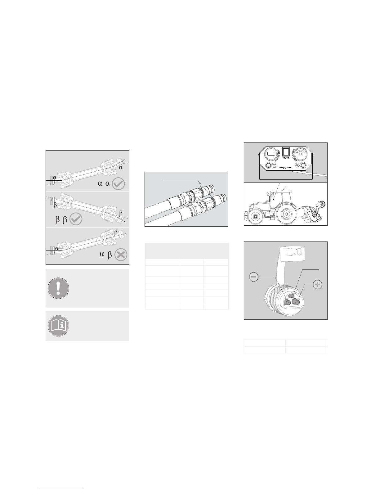
2) Check that the PTO shaft works properly:
a. WITHOUT alignment system or WITH EVA align-
ment system
If the PTO shaft becomes too
short, it is recommended to
mount the ADAM™ system.
= >max15˚
= >max15˚
B
A
15
14
Function Hydraulic
hood
Compacting
roller or
grader blade
MIDIPIERRE 6-10 l/min /
MIDIPIERRE dt 6-10 l/min 6 -10 /min
2 -3 l/min
MIDISOIL dt 6-10 l/min 6-10 l/min
MULTIFORST 10-14 l/min 25 -35 l/min
STARSOIL 10-14 l/min 25 -35 l/min
SUPERSOIL 10-14 l/min 25 -35 l/min
MAXISOIL 10-14 l/min 70 -95 l/min
Voltage 12V
Fuse 16A
If they do not work in the
described positions, the PTO
shaft and all the transmission
components wear prematurely.
The product warranty becomes
null and void.
Read the PTO shaft
manual!
2) Check movements of the hydraulic functions and
if necessary adjust at the following flow rates:
b. WITH ADAM™ alignment system
1) Connect a pair of hydraulic pipes marked with
the same colour to the tractor inlets by means of
quick couplings.
4.2.4 Connection of hydraulic quick couplings
for auxiliary functions
same colour
=
=
≠
If the tractor does not have a suitable socket,
connect the wires to another electricity source
according to the following indications.
On some models, the cooling system of the
transmission is electric.
4.2.5 Connection of electrical sockets
Position the control panel in the cab and fix it
properly.
Connect the three-pole electrical power connec-
tor to the tractor's socket.
not connected

15
14
DEUTSCHESPAÑOL ITALIANO ENGLISHFRANCIS
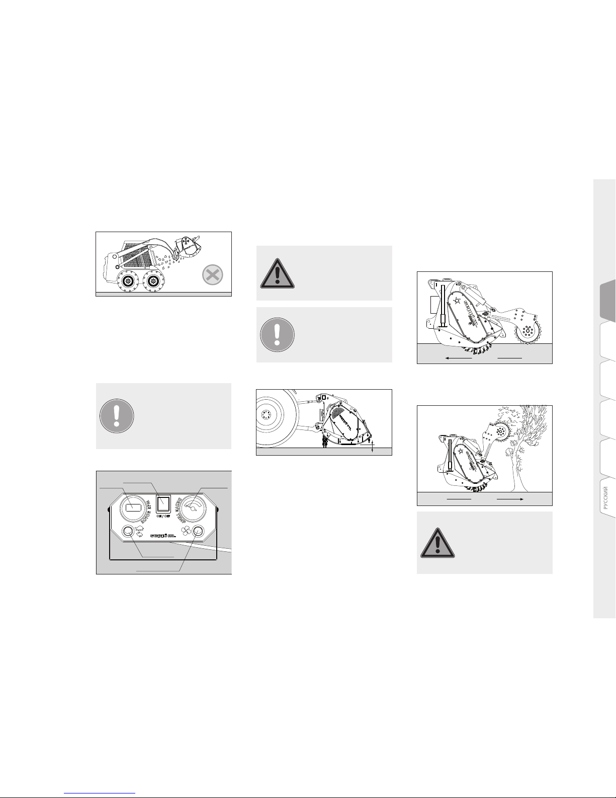
Only work with the hood open
when absolutely necessary!
The grader blade has the following functions:
1) Compacting the soil
2) Evenly distributing the material
3) Levelling the soil
- Lift the grader blade when transporting the
machine.
- Lower the blade during use.
- Push the blade down to increase compacting
pressure (indicated on the pressure gauge).
- Adjust inclination of the blade to move material
to the right or left.
- When the machine is parked, the grader blade
must rest on the ground.
4.3.5 Adjusting grader blade
Brown +12V
Blue GND
1) Check the features of the hydraulic motors and
valve blocks in the attached guide, if the machine
is supplied with them.
2) Follow the installation and commissioning in-
structions in the attached guide.
4.2.6 Connecting a hydraulically driven
machine
Connecting wires:
If the machine is equipped with one or more sup-
port stands, they must be closed during work.
1) Open the hood to expose the rotor, to fell trees
and to reduce power output
2) Close the hood to improve the degree of mulch-
ing
4.2.7 Support stand
4.3.2 Adjusting hydraulic hood
1) See points 4.2.1
4.3 Adjustments
4.3.1 Adjusting 3-point-linkage
manually or hydraulic
If the machine has support skids or adjustable
conveying skids, proceed as follows:
1) Lift the skids to bring the rotor close to the
ground
2) Lower the skids to move the rotor away from the
ground
The roller has the following functions:
1) Levelling the machine
2) Compacting the soil
3) Guard frame to push trees and shrubs
4.3.3 Adjusting support skids
4.3.4 Adjusting compacting roller
Some models are supplied with
non-adjustable anti-wear skids
as standard.
BAR PSI
BAR PSI

17
16
If the machine has hydropneumatic suspension
(nitrogen accumulator) for the compacting roller
or grader blade, it can be activated or deactivated
by acting on the valve mounted on the line.
- Close the valve to deactivate the suspension.
- Open the valve to activate the suspension.
4.3.6 Adjusting hydropneumatic suspension
of roller or blade
ON OFF
Bring the anvil close to the rotor to improve
mulching or move it away to reduce the power
output.
Adjust the anvil as follows:
1) loosen the screws fastening the anvil,
2) adjust the distance of the anvil with the adjust-
ment screws on the frame,
3) check the distance of the anvil from the rotor,
4) tighten the screws blocking the anvil.
1) Presence and integrity of all stickers indicated
in chapter 2
2) Integrity of front protection (row of chains)
3) Conditions of PTO protection (tractor - tool)
4) Conditions of PTO shaft protection
4.3.7 Adjusting anvil
5.1 Checks prior to work
5.2 Tractor selection:
5. OPERATION AND USE
The operator must know the
features of the machine and be
capable of using it properly.
The operator must prohibit
anyone from approaching and
using it. It must never be left
unattended while running or
be climbed on.
Do not work in positions where
the mulcher rotor can cast
objects towards the cab or oth-
er parts of the tractor causing
damage or personal injury.
5) Are the protections on the tractor intact and
operational?
6) Are the pins for the three-point linkage
blocked?
7) Integrity of the belt protections
8) Integrity of protections around tools
9) Integrity of safety valves
10) Check tractor stability with possible weighing
of the train.
Tractors can be used with the following features:
- super-reduced gears or continuously variable
transmission with minimum speed no higher
than 0.3 km/h
- Forestry tyres
- Cab safe according to ROPS/FOPS standard
5.2.1 Farming or forestry tractors
Tractors can be used with the following features:
- Hydraulic system capable of driving a stone
crusher according to specifications in the technical
commercial documentation.
- Cab safe according to ROPS/FOPS standard
5.2.2 Tractor with hydrostatic drive, earth
moving equipment
1
1
32
17
16
DEUTSCHESPAÑOL ITALIANO ENGLISHFRANCIS
Before starting to work with
the stone crusher, inspect its
designated work area.
- Lift the machine a few cm so that the rotor does
not touch the ground
- Take care to correctly angle the PTO shaft ac-
cording to the indications in chapter 4.2.3
- Start the tractor PTO at moderate speed,
selecting the speed prescribed for the mulcher
(540 or 1000 rpm). In case of hydraulically driven
machine, feed the pump/s.
- Increase engine speed to gradually reach the
nominal rpm (540 or 1000 rpm)
- Lower the machine to the desired depth by acting
on the tractor lift or on the position of the com-
pacting roller.
- Advance by pulling the machine (normally in
forward gear) to till the soil and to crush the
- Turn off the main switch when work is over to
avoid discharging the battery.
- Connect the system following the instructions in
point 4.2.5.
- Turn on the main switch. The switch lights up.
- Turn on the fan switch. The switch lights up.
- Check operation of the thermometer and of the
fan.
5.3 Starting cooling system:
If the transmission temper-
ature exceeds 90°, stop the
machine and check the cooling
system. Never work without
the cooling system and tem-
perature sensor running!
The performance capacity of
the machine must NEVER be
exceeded.
5.4 Start-up and processing
min 5 cm
stones or, for forestry work, feed the crusher
with material to be mulched.
- Close the hood to improve mulching.
- Advance by pushing the machine (normally in re-
verse) to fell the trees. Open the hood and adjust
the compacting roller (4.3.2 and 4.3.4)
main power switch
rev counter
radiator on-off
switch
high-low speed
change
radiator oil
temperature
indicator
Never fell trees more than
twice as high as the forestry
tiller or stone crusher (with
or without compacting roller).
They could fall on the operator.
movement
movement

19
18
- In both cases, choose the minimum forward
speed possible and increase if necessary.
- Stop or slow down when the tractor is exces-
sively stressed to avoid stalling the rotor.
tree height limit
machine height
A
2xA
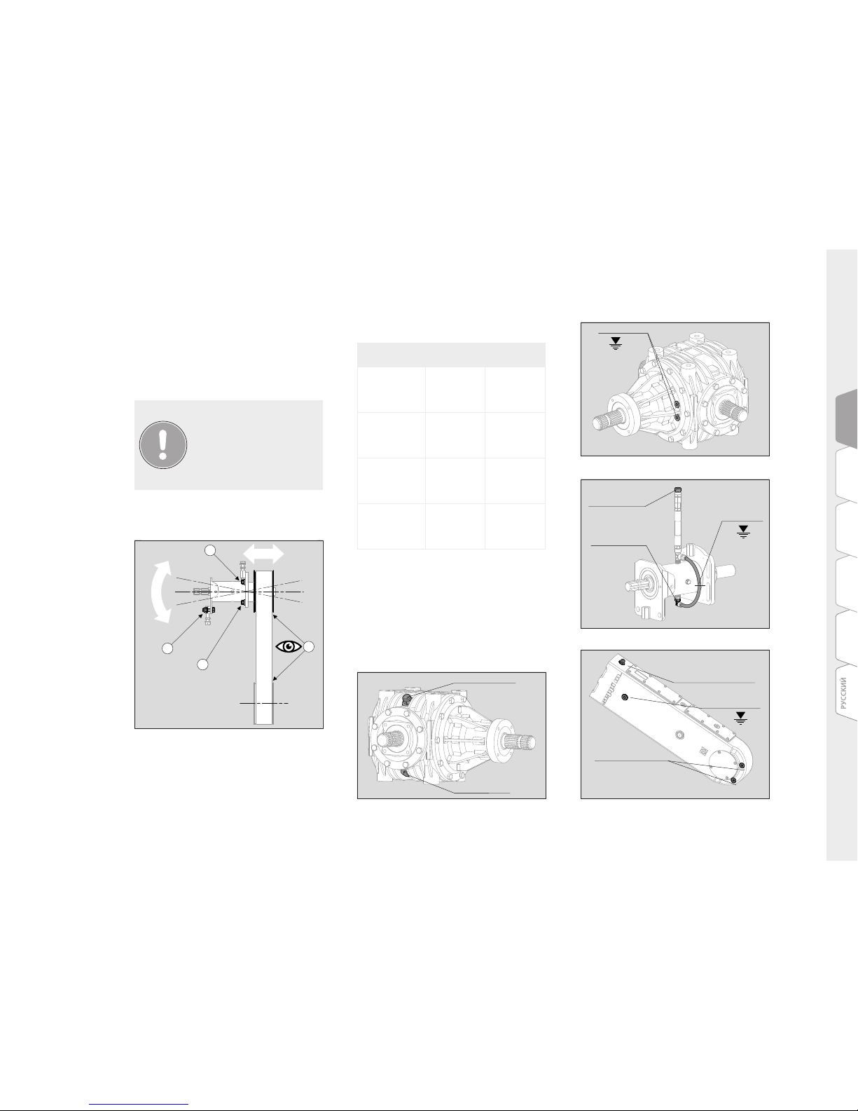
6.1.1 Setting the cogbelts
The precise alignment of the cogbelt pulleys is
very important to guarantee long life.
To align them:
-Bring the belt to the desired tension, as de-
scribed above, without tightening the screws
-Only tighten the screws at the side
The operator is responsible
of making sure no persons or
objects are in the machine's
range of action!
5.5 Safety distances
The following safety distances must be respect-
ed for all forestry tillers/stone crushers
30 m 30 m
15m15m
All maintenance on the ma-
chine must be carried out with
the tool on the ground and the
tractor stopped, removing the
keys from the dashboard.
Interventions must be carried
out in safe conditions, using
appropriate tools and personal
protective equipment.
6. MAINTENANCE
To check the belt tension, use
a belt tension gauge to detect
belt frequency. A digital guitar
tuner which shows the frequen-
cy can also be used instead of
a belt tension gauge. (Smart-
phone)
To adjust the tension of traditional belts, proceed
as follows:
- unscrew the fixing screws and nuts of the belt
protection,
- after having opened the protection, loosen the
screws and nuts securing the extension to the
frame, without removing them,
- stretch the tie rod to reach the correct belt
tension,
- tighten the screws and nuts loosened in point 2,
- close the belt protections
All the operations not de-
scribed in this manual can
only be carried out by qualified
and specifically specialised
personnel.
There are three types of lateral transmission:
V-belts, cogbelts and parallel axis gearboxes.
To adjust tension, strike the middle of the belt
with an object and measure the frequency with a
measuring instrument.
Check belt tension every 50 hours, as indicated in
the diagram below.
6.1. Belt tension check and adjustment
Model Frequency (from – to)
MIDIPIERRE 41-46 Hz
MIDIPIERRE dt 36-40 Hz
MIDISOIL dt -
MULTIFORST 35-45 Hz
STARSOIL -
SUPERSOIL 35-45 Hz
MAXISOIL 27-30 Hz
19
18
DEUTSCHESPAÑOL ITALIANO ENGLISHFRANCIS
6.2 Lubrication
6.2.2 Changing oil
Before starting lubrication, clean all the lubri-
cation points with a rag.
Use grease pumps with clean nozzles to avoid
introducing impurities into the lubrication
points.
After the first 50 hours, and then every 500
hours, it is necessary to change the gearbox oil.
Respect the following levels:
- Gearbox
During a test start, always
remain a safety distance away
of at least 2 m and NEVER turn
the adjustment screws while
the machine is running. Wait
for it to come to a full stop
before resuming maintenance.
6) Repeat the points above until the pulleys are
perfectly aligned
7) The pulleys are perfectly aligned when the belt
remains in the middle of the pulley
6.2.1 Recommended lubricant
Model Component Oil
MIDIPIERRE
MIDIPIERRE dt
MULTIFORST
Gearbox
SYNTHETIC
GEAR OIL ISO
220
(DIN 51502)
SUPERSOIL
MAXISOIL
Gearbox
SYNTHETIC
GEAR OIL ISO
320
(DIN 51502)
All models Extensions SYNTHETIC
GEAR OIL
ISO 220 (DIN
51502)
MIDISOIL dt
STARSOIL
Parallel gear
transmission
SYNTHETIC
GEAR OIL
ISO 150 (DIN
51502)
3) Act on the tie rod to change angling of the
extension
4) Tighten the remaining screws to fix the exten-
sion
5) Visually check alignment by starting the
machine briefly without belt protections and
without load
- Extensions
- gear transmission
3
1
5
2
Breather filler cap
Breather cap
and drain plug
Breather filler cap
Drain plugs
Oil level
Breather filler
cap
Drain plug
Oil level
Oil level

21
20
The cooling circuit guarantees correct lubrication
and ideal temperatures for the gearboxes. Always
check that the cooling system works properly.
The filters must be changed every time oil is
changed.
6.2.3 Cooling system
(MIDISOIL dt, STARSOIL)
6.2.4 Lubrication plan
Oil Grease
PTO shaft
40 h
Gearbox
rotation
40 h
PTO shaft
40 h
Rotor
8 h
40 h
hood bushes
Hood opening
cylinders joints
40 h
roller
bearing
8 h
6.5.1 Replacing swinging hammers
To remove and replace the swinging hammers,
proceed as follows:
2) open the belt protection cover
3)
disassemble the closures, installed at the sides of the
machine, to be able to pull out the hammer support bars
If damaged or worn, restore
them immediately, as well as
safety stickers if damaged or
missing.
6.3 Oil leaks
6.5 Replacing tools
6.4 Safety devices and information
If any machine component leaks oil, the oil
must be recovered and worn components
restored.
Use original Seppi components for proper
operation of the rotor.
Check the chains, rubbers, guards of the PTO
shaft, etc. every 8 hours
Oil leakage on the ground
causes pollution!
Using non-original spare parts
makes the rotor warranty null
and void.
1) lift the rear hood with the hydraulic controls
and secure it mechanically
against accidental closures
This manual suits for next models
6
Table of contents
Popular Farm Equipment manuals by other brands

roost&root
roost&root Backyard Chicken Coop 2 Assembly instructions

Westeel
Westeel WaterTank Flat Roof Installation and Storage Instructions

Land Pride
Land Pride AFM4214 Series Operator's manual

Mayer
Mayer 6160 Big Bale Breaker operating instructions

MacDon
MacDon 9000 Operator's manual

IntelligentAg
IntelligentAg Engage Zone Control Maintenance manual


IDROFOGLIA
IDROFOGLIA TURBOCAR J1 Operating instructions manual

NAMYSLO
NAMYSLO DEEP Series manual

COTSWOLD
COTSWOLD CLUSTER-FLUSH installation instructions

Hillside Cultivator
Hillside Cultivator Blueberry Cultivator operating instructions

Hedensted Gruppen
Hedensted Gruppen HG FEEDER 600 user manual

Kemper
Kemper 300F Operator's manual