manuals.online logo
Brands
  1. Home
  2. •
  3. Brands
  4. •
  5. roost&root
  6. •
  7. Farm Equipment
  8. •
  9. roost&root Backyard Chicken Coop 2 User manual

roost&root Backyard Chicken Coop 2 User manual

Winter
2023
Model 2
V1.0
Standard Model Shown With Optional Smoked Roof, Waterer & Feeder
Assembly Instructions
Backyard Chicken Coop ™
These written instructions, as
provided with your purchase, will
always be the latest iteration of the
instructions and match the coop
shipped and provide the most
complete up-to-date information.
We depend on feedback about our
instructions to implement changes
to future versions. Please know
that we value your input to that
ongoing process and endeavor to
produce instructions that are as
effective as possible for a wide
variety of customers.
Assembly
Overview...
Use your phones camera to read QR Code.
Video overview of assembly.
Help Text-line: 512-596-5200
EMAIL: [email protected] re: Assembly Support
VOICE: 877-741-2667 | Assembly Support ext 3
Copyright ® Roost & Root all rights reserved. This document is intellectual property of Roost & Root and is being provided to you for your own personal limited use as a
paying customer for the purpose of assembling your coop. Roost & Root claims all available Federal protection for the name Round-Top Coop ™ , our protected designs and
trade dress as is allowed by any and all Federal intellectual property protection laws. We invest heavily in your coop and work very hard to do a good job and it is only fair that
our workers benefit for their hard work.
FOR BOTH STANDARD AND XL MODEL
Assembly Instructions
Backyard Chicken Coop
Model 2 Winter 2023 V1.1
Copyright ® Roost & Root all rights reserved.
Parts List
Tools you'll need...
A level (or use your cell phone)
Hammer
Drill... preferably
a cordless drill
with 2 charged
batteries.
Be careful not to get caught in coop. Children should not play in coop as
the doors are not designed to allow easy exit.
Spending the time up front to identify all the parts and lay them all out will
pay off in the long run and make assembly go more smoothly. The
instructions are intended to be read in page order as, the information builds
in that way, then referenced during assembly. Pre-reading the instructions
will help immensely.
Phillips Screw
Phliips Bit
Bit Holder
= Colored Arrows
Indicate Type And
Direction Of Screws
3" T25 Screw
Color of screws may vary.
T25 Torx Bit
Written Parts List
Run
A1 Left Side
A2 Right Side (door)
A3 Right Transom (thin)
A4 Front (waterer panel)
A5 Back
A6 Right Run Floor
A7 XL Sunroom Front
A8 XL Sunroom Back
A9 XL Sunroom Tops (2)
"B" Parts - Roost & Eggbox
B1 Roost Front
B2 Roost Mid Wall (egg hole)
B3 Egg Box Floor
B5 Roost Left (Door)
B6 Roost Right
B7 Roost Bars (2)
B8 Roost Back
B9 Roost Arcs (3 same)
Roof
C1 Roof Panels (3x 58")
C2 Eaves (2x)
C3 Support Battens (3)
"D" Parts - Accessories (if purchased)
D1 Waterer | Cap | 3 Nipples
D2 Waterer Bracket & Screws
D3 Feeder & Cap
D4 Sunroom Shade (Assembly)
D5 Dust Bathing Box (Assembly)
D6 Egg Box Liners (2)
D8 9 Standard Storm Panel Kit (35 Clips) xtras
D9 12 XL Storm Panel Kit (50 Clips) xtras
D10 Garden Boards Set & Liner
D11 Feeder Bezel
D12 Stakes (6x)
"F" Parts - Assembly Kit
F1 3" Screws (Standard/ #90 XL/ #100 )
F2 1-5/8 Screws ( #30 )
F3 Hasp Sets w/screws (4X)
F4 Roof Screws ( #30 x1") and ( #30 1½")
F5 Gravity Gate Latch w/screws (1x)
F6 T25 Bit (1x)
F7 Phillips Bit (1x)
F8 Bit Holder (1x)
F9 T-20 Bit (1x)
F10 Spring Snaps (5x)
Extra Screws Are Provided
Assembly Instructions
Backyard Chicken Coop
Model 2 Winter 2023 V1.1
Copyright ® Roost & Root all rights reserved.
Orientation
Front
Left
Right
Back (We recommend having the back side of your coop facing North)
XL Model Shown With Optional Waterer, Feeder and Roof.
XL
Egg Box
Water
Feed
Roost
Egg
Collection
Roost Door
Vent
Vents
Water
Support
Bracket
Turn Out
Door
Assembly Instructions
Backyard Chicken Coop
Model 2 Winter 2023 V1.1
Copyright ® Roost & Root all rights reserved.
Concepts
Sorry... a little reading ;-)
Sealing & Care:
We recommend you leaving your coop natural. You can stain your coop but should only use a "breathable" low VOC water based stain. You can have color added to these products
too...like painting, but it's a wood stain that lets the wood breathe. Cedar will last outdoors in its natural state for many years, better than almost any other wood. Sealing can keep the wood
from going grey. That's the main benefit. Clean wood with mild detergent and water or with a commercially available coop cleaner as needed. Glues used in all joints are completely
waterproof and all metal parts are galvanized or have exterior rated coatings.
Placement:
Easy access to water/feed and clear access to doors is needed. Sunlight is not all bad, and the roof does provide shade. Sunlight does a good job at disinfecting the ground under the coop.
Fifty percent (50%) or more of direct sun is preferred. Good air movement around your coop is more important than anything else. The proper side should face North if at all possible.
Remember... High ground is dry ground. For coop doors to open easily over time, the coop must be level.
Digging Predators:
Diggers are the prime nuisance to chickens. By far dogs are the most common digger. Other "wild" animals, while more rare, certainly can dig too. If you ’ re worried about diggers, stack
heavy block shaped rocks around perimeter of coop to make getting under more difficult. Better yet, bury them around the perimeter just below grade. You can also attach a strip of wire that
extends out from the bottom rails, and bury below the surface of the soil. We recommend dirt in bottom of coops that has good drainage. Pine shavings, straw or shredded junk mail can be
used in laying areas... but is not recommended in the main run areas.
More About Cedar:
Your coop is built from rough cut domestic cedar. Our 2x2's are actually custom milled. Wood deemed defective is culled during milling, cutting and in fabrication... about 5%-10% does not
"make the cut". Knots, blemishes, fraying, coloring variations, minor surface cracking, slight warping and periodic worm marks are normal parts of natural wood products. We try to make it to
where a reversible part always has a “ pretty side ” and take care to make the “ pretty side ” show on all parts. If you ’ re unhappy with a piece of wood we fabricated into your coop, send us a
picture. We want you to love every piece of your new coop.
Staking for Wind:
If you expect your coop to be in winds greater than 35mph (tropical storm force wind) then you will want to stake your coop to the ground in a way that is appropriate for your soil
and locale. You can always contact us for guidance related to your particular situation.
Understanding these concepts / conventions will help guide you through the instructions.
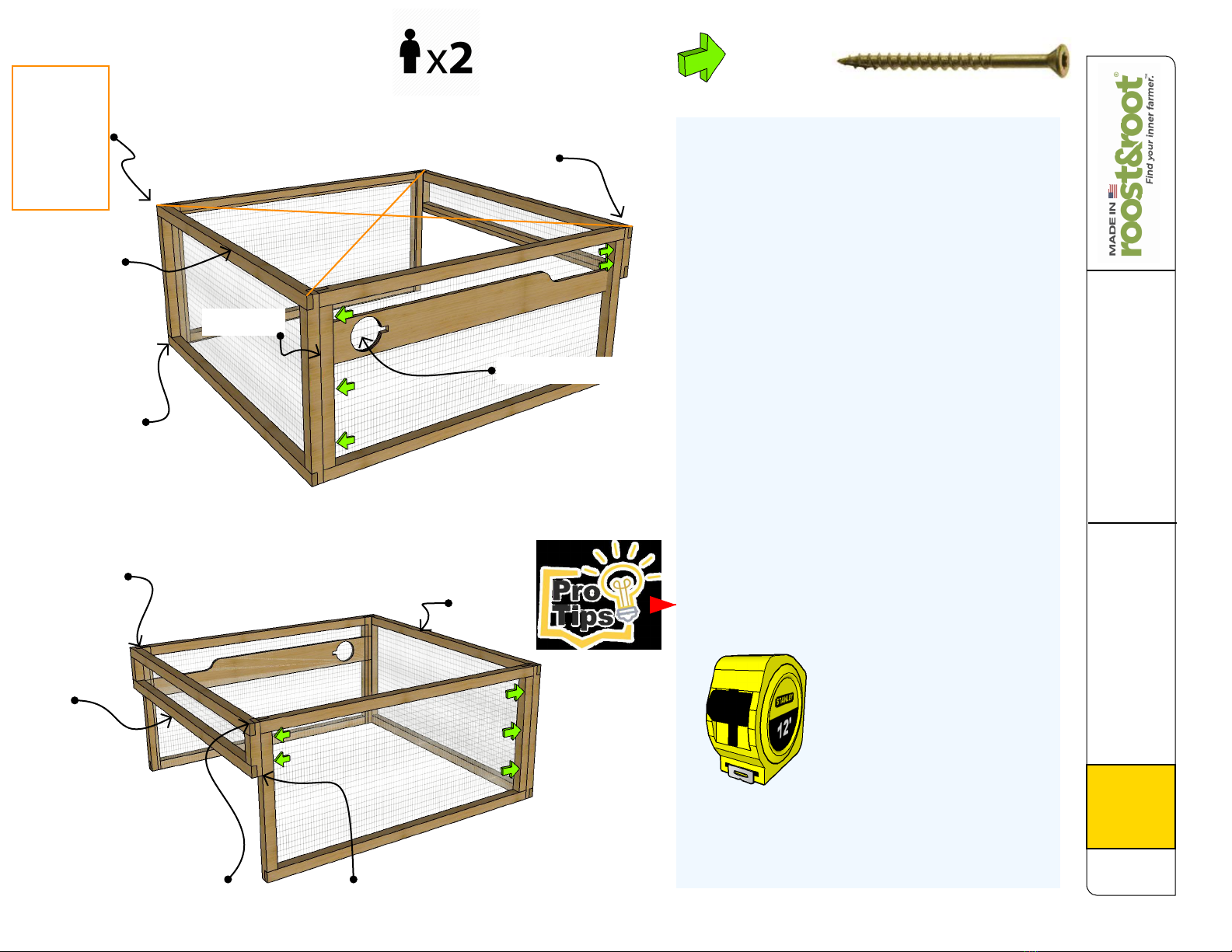
1 Mating edges of parts to be flush and tight (when called for) will keep measurements in tolerance as the coop grows in size.
2 CRITICAL: Having a flat area is required for the coop to assemble properly and operate properly.
3 We estimate about 2 hours for someone of ordinary skill to assemble. Two people will certainly make some steps easier.
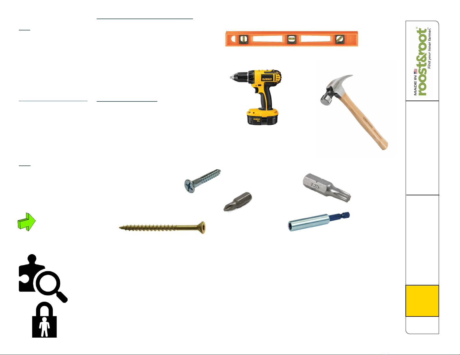
4 You will need a drill (preferably cordless) maybe a tape measure and a hammer. Everything else is provided.
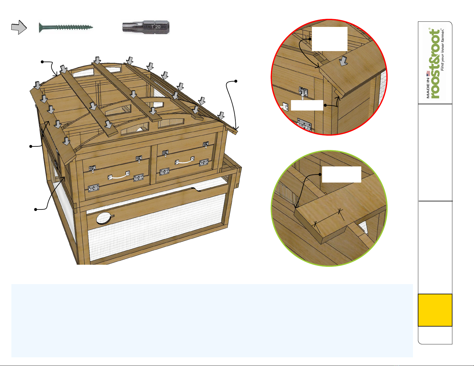
5 Drive screws only deep enough to hold parts tight and not bury the heads too deeply as water can sit in the divots and it may cause
softening of the wood and prematurely loosen screws. It will also greatly decrease your ability to easily disassemble a part if needed.
6 You may end up directly driving in a screw. The provided screws are very aggressive and can drive with no pre-drilled hole. Keep screw
entry points in the meat of the wood and not too close to edges. Screws in knots or close to edges should for sure be pre-drilled.
7 Rough Cedar may have knots, cracks or frays that are normal. We cull and cut around most imperfections we deem structurally problematic
during fabrication. If you get a piece that you feel is not beautiful, please let us know so we can address your concern.
8 We hand fabricated your coop with human carpenters. We work really hard to not make mistakes. On the rare occasion that we either
misfabricated a part, a part was damaged in shipping, or we forgot to package a needed part, contact us and we will ship out a replacement
part for you at no cost.
9 We recommend dirt floors in the runs of coops. A trimmed rubber mat can be placed in the bottom of egg boxes and you may wish to put
pine shavings or shredded junk mail in them. They are left wire so they can be cleaned in the event of a broken egg.
Assembly Instructions
Backyard Chicken Coop
Model 2 Winter 2023 V1.1
Copyright ® Roost & Root all rights reserved.
Step 1A - Run
1A1 Left Front Corner: Using the provided T25 Torx Bit
in provided Bit Holder and your drill, drive 3" T25 Screws
from panel A4 into panel A1 through pre-drilled holes.
Panel A1 overlaps panel A4 as illustrated. Wire side goes
to the inside. Make edges and tops flush. (The top of the
A1 panel will have pre-drilled holes from the underside
going up.)
1A2 Left Back Corner: Drive 3" T25 Screws from panel
A5 into panel A1 through pre-drilled holes. Panel A1
overlaps panel A5 as illustrated. Wire side goes to the
inside. Make edges flush and top of A1 flush with the A5
mid-rail as illustrated by the dashed red line.
1A3 Right Side: Drive 3" T25 screws (2 of them) from
inside of A4 and A5 panels into the A3 right side transom
panel. Top of A3 is flush with tops of A4 and A5 and
attaches onto the outside as illustrated.
:-) Here we go !
= Direction
Of Screws
3" T25 Screw
Color of screws may vary.
A5
The first step is to attach the left and right sides to the
front and back panels to form the "run". The run is
where your chickens will live during daylight hours.
Your local dirt makes the best surface and will allow
chicken poop to decompose more readily and lets
your birds get a "dust bath" when they need. It's also
easy on their feet.
Left
Side
Back
This wire removed
if you ordered a waterer.
Make side
edges flush
Make Bottoms
Flush
A1
A4
A5
Flush Tops
A3
A3
A3 Top Flush with
A5 & A4 Top Rail
Flush Edges
Flush Tops
Front
Right
Side
An extra person while
not required, would
be helpful for these steps.
While certainly not
mandatory, best practice
would be to "square"
the run by measuring
corner to corner as
illustrated by the orange
lines in the top figure and "rack"
(move) the run from corner to corner
until the two measurements were the
same.
See note
about
"squaring".
Corner-to-
Corner
should be
+/- 76
inches...
*Wire goes to inside of
coop...
A1
Pre-Drilled
Holes In
Top Edge
Only drive screws deep enough for them to
hold. The hole from driving them too deep
holds water and causes premature loosening.
Assembly Instructions
Backyard Chicken Coop
Model 2 Winter 2023 V1.1
Copyright ® Roost & Root all rights reserved.
Step 1B - Run
1B1 Egg Box Floor: Place panel B3 into place as illustrated. If needed, temporarily loosen screws installed in prior steps to allow for insertion. Tighten all screws together keeping
edges flush. Wire side faces down.
1B2 Planter Floor: Place panel A6 into place as illustrated. If needed, temporarily loosen screws installed in prior steps to allow for insertion. Tighten all screws together keeping
edges flush. Wire side faces down.
:-) About done with the run !
= Direction
Of Screws
3" T25 Screw
Color of screws may vary.
Next you will install the eggbox floor and planter floor into the run. This will "lock the run into being square.
Left
Side
Front
Wire Face
Down
A6
B3
Wire Face
Down
Note: If you did
not order optional
waterer this opening
will be wired.
Assembly Instructions
Backyard Chicken Coop
Model 2 Winter 2023 V1.1
Copyright ® Roost & Root all rights reserved.
Step 2A - Roost &
Roost Bars
FIG 2A1 Roost Back Wall: Drive 3" T25 Screws up from panel A5 into
bottom rail of B8 making sure back edge is flush and left edge is positioned
as indicated... not over A1. Next screw up from panel B8 into arc B9 as
illustrated keeping edges flush. Pretty side faces out to the back.
FIG 2A2 Inner Wall: Drive 3" T25 Screws down from the bottom rail of panel
B2 into egg box floor edge installed in prior steps. Make sure edges are flush
the B2 panel does not overlap the A1 left side panel. See illustration. Driving
screws up through the top rail of B2 into the bottom rail of B9 , install B9 as
illustrated making sure edges are flush.
Roost Bars: The 2 B7 Roost Bars are held in place between the B8 Back
Wall and B2 Inner Wall using provided T-20 1-/5/8 screws... one on each end
of each roost bar. Position the center of the roost bar over the center of the
pre-drilled hole to properly position bars. See figures 2A1 and 2A3 for screw
positions and Fig 2A2 to see where the bars go...
:-) On to the roost...
In this step you'll start to build out the roost. The roost is where the
chickens sleep (roost) at night. It's higher where they feel safer, and
has more protection from wind and rain. They will jump up to the
roost bars and perch (roost) there while they sleep. We cut roost bars
into an octagonal shape to match how chicken feet wrap around the
bar.
Fig 2A1
B2
B8
B9
B9
Fig 2A2
Ledge
this
side.
Ledge
this
side.
A5
Inside
A1 Side
Ledge
Flush
Pretty side
ledge flush
Grey Arrow = 1-5/8 T-20 Torx Screw (roost bars)
+
Pre-Drilled
Holes For
Roost Bars
Inside
of A1
Panel
Fig 2A3
Front Screws
For Roost
Bars
B7
Roost Bars
Assembly Instructions
Backyard Chicken Coop
Model 2 Winter 2023 V1.1
Copyright ® Roost & Root all rights reserved.
Step 2B - Roost Front
& Sides
B1
B9 - Pretty
Side Out
A4
B1 flush with this edge of A4
:-) Starting to look like something...
Fig 2B1
FIG 2B1 Egg Box Front: Drive 3" T25 Screws up from panel A4 into bottom
rail of B1 making sure front edge is flush and left edge is positioned as
indicated. Next screw up from panel B1 into arc B9 as illustrated keeping
edges flush.
FIG 2B2 & 2B3: Install the left side B5 Roost Wall (has access door) by
driving 3" T25 Screws up from panel A1 into bottom rail of B5 making sure
front edge is flush and ends are flush too.
Finish attaching the sides of the B5 Panel to the B1 Front and the B8 Back by
driving three screws through the sides of B8 and B1 into the sides of B5 . See
figures 2B2 and 2B3 for guidance.
Drive 3" T25 screws down through the bottom rail of B6 Right Side into edge
of A6 planter floor and the eggbox floor as shown in Fig 2B2 .
Finish the install by installing the three screws from B8 and B1 into B6 sides a
indicated in illustrations 2B2 and 2B3 .
Finally, reaching over, drive screws from sides of B2 Inner Wall into mid
uprights of B5 and B6 on both sides to lock the inner wall into place.
Keep all edges flush as required.
Fig 2B2
Fig 2B3
B2
B6
B5
A1
A6 Planter
Floor
B8
From Inside
From Inside
Assembly Instructions
Backyard Chicken Coop
Model 2 Winter 2023 V1.1
Copyright ® Roost & Root all rights reserved.
Step 3 - Roof Frame
C2 Left & Right Eaves: Identify the C2 eave boards... they are identical. Using the 1-5/8 T-20 screws attach the eave boards to the left and right sides of coop using 5 screws in each
eave. Use figures 3.1 and 3.2 as guides. The eave should overhang about an inch on each end. Drive screws down straight into B5 and B6 side tops.
C3 Roof Support Battens: Identify the (3) C3 roof support battens. Use 3 T-20 screws each at the positions illustrated to attach to the tops of the B9 arcs. They will overhang about
two inches.
;-) No ladder required...
Fig 3.1
Fig 3.2
Grey Arrow = 1-5/8 T-20 Torx Screw (roost bars)
+
C2
Eave
Reinforced
Edge Down
Beveled
Edge Up
1" Over
2"
Eave 2"
Overhang
C2
B6
B5
B9
B9
B9
B9
Fig 3.3
C2
Eave
Assembly Instructions
Backyard Chicken Coop
Model 2 Winter 2023 V1.1
Copyright ® Roost & Root all rights reserved.
Step 5A - Right Run
Side (turn-out door)
:-) Like, you're pretty much done!
Fig 5A1
F3 Hasps: Identify the 4 F3 Hasps and screws as illustrated in Fig 5A5. Using predrilled holes in edges of panels A4 front and A5 back install the
hinged body side of hasp. With the A2 panel flush at the bottom, position and install the F3 Catch on edge of A2 so that the hinged body can fold over
the catch and a clip can be installed. Repeat for all 4 positions.
F5 Gravity Gate Latch: Identify the F5 Gravity Gate Latch and screws as illustrated in Fig 5A6. Using predrilled holes in both edge of door frame and
side of A2 panel, install latch using illustrated screws. Install clip when done to assure door stays locked. Remove shipping screw from door frame of
A2.
A2
A4
A5
Flat Head
Phillips
Screw
Bit
Hinged
Body
Catch
Clip
F3 Hasp
F5 Gravity
Gate Latch
Pan Head
Phillips
Screw
Door Arm
Body
Clip
A2
Fig 5A2
Fig 5A3
Fig 5A4
Same procedure
as front side
Use pre
drilled
holes...
You align
and drill...
Find door shipping
screw and remove
Use pre-drilled
holes
The right side of the run is completely removable by 4 locking hasps for easy periodic rake out. It also has a locking integrated turn-out door to let your
hens out for daytime foraging.
Skip this step if you bought XL model.
Flush Bottoms
Fig 5A5
Fig 5A6
Assembly Instructions
Backyard Chicken Coop
Model 2 Winter 2023 V1.1
Copyright ® Roost & Root all rights reserved.
Step 5B - Optional -
Garden
Herb garden, or not !
Fig 5B1
Roof and eave omitted
for clarity...
D10 Side
D10 Front
Fig 5B2
Back Edge
Flush
Inside
Edge
Flush
D10 Planter: Identify the D10 planter box sides and front. Using the illustrations and the 1-5/8 T-20 screws, install the planter area as indicated. When
done, place the thin black HDPE liner in the bottom so that if you place some pots in there they will sit more level... and it could also block out some
snow.
The right side has an optional planter box area where you can keep small potted plants. If you ordered it this is the best time to install it. The roof hangs
over to provide more cover on the right side.
HDPE Bottom Liner
Assembly Instructions
Backyard Chicken Coop
Model 2 Winter 2023 V1.1
Copyright ® Roost & Root all rights reserved.
Step 5C - XL Right
Run Side (turn-out
door)
:-) Like, you're pretty much done (XL) !
A7, A8 & A2: Identify panels A7 & A8 and using T-25 3" screws attach from the inside of A7 and A8 to A2 as illustrated in figure 5C1. Panel A7 is the front and A8 is the
back.
A9's: Identify the two A9 panels and using T-25 3" screws first attach the outer A9 panel over the top of A2 and A7 and A8 keeping all edges flush. Attach the inner A9 as
illustrated. Inner A9 will fall short of the ends of A8 and A7 so that it can tuck under the A3 panel.
F3 Hasps: Four F3 hasps attach the run assembly to the main coop as illustrated in Fig 5C3. Two on front, and two on back. See Fig 5C4 to identify correct screws.
F5 Gravity Gate Latch: Identify the F5 Gravity Gate Latch and screws as illustrated in Fig 5C2. Using predrilled holes in both edge of door frame and side of A2 panel,
install latch using illustrated screws. Install clip when done to assure door stays locked. Remove shipping screw from door frame of A2.
A2
A7
A9
Fig 5C3
Fig 5C5
Use pre
drilled
holes...
You align
and drill...
Use pre-drilled
holes
The right side of the run is completely removable by 4 locking hasps (2 on front and 2 on back) for easy periodic rake out. It also has a locking integrated turn-out door to let
your hens out for daytime foraging.
XL model only.
Flat Head
Phillips
Screw
Bit
Hinged
Body
Catch
Clip
F3 Hasp
Fig 5C4
F5 Gravity
Gate Latch
Pan Head
Phillips
Screw
Door Arm
Body
Clip
Fig 5C2
A8
Back
A9
Two hasps on the back too...
Fig 5C1
A3
Flush
Assembly Instructions
Backyard Chicken Coop
Model 2 Winter 2023 V1.1
Copyright ® Roost & Root all rights reserved.
Step 6 - Optional
Waterer & Feeder
6.1 Install D2 Waterer Bracket: Attach the support arm to the support block using T-20 screws. Using a tape
measure, attach the support block to the side rail of A5 back panel 11-3/8 inches up from bottom panel edge using
T25 screws.
6.2 Install D3 Feeder: Feeder drops in at an angle from the outside and is locked in place by dropping in bezel
around the feeder. Face the open cup area of feed delivery towards inside of coop. Feed cap may be inside your
feed tube.
6.3 Install Poultry Nipples: Fig 6.3 illustrates installation of the standard poultry nipple. After inserting nipples,
insert waterer into position as indicated in Fig 6 roating as needed for nipples to clear then fill after inserted and
resting in the waterer bracket installed in Fig 6.1
Note: Separate instructions are provided with the optional Freeze Guard Poultry Nipple.
6.3 Standard Poultry Nipple Installation
1st install rubber grommet
into holes. Rotate to seat.
2nd force fit by pushing, the nipple
into the grommet. Protect your
hand with a towel if needed.
Fig 6.1 - Left Panel
Omitted For Clarity
Fig 6
6.2 Feeder
Waterer Cap With
Slotted Vent Hole
For Air And/or
A Exit For Heater
Wire.
11-3/8"
D2 Support
Arm
Rotate waterer to insert
and rest on this bracket.
D11 Feeder
Bezel
D3 Feeder
D11 Feeder
Bezel
D2
D2 Bracket
D1
Assembly Instructions
Backyard Chicken Coop
Model 2 Winter 2023 V1.1
Copyright ® Roost & Root all rights reserved.
Step 7A - Optional
Sunroom Shade -
Frame
7.1 Connect Left & Right Frames: Using T25 screws into pre-drilled
holes in connectors, layout two frames with 3-7/8" between them and
connect as illustrated in Fig 7.1
7.2 Install Supports: Using T25 screws, screw in each bottom leg of
supports into corners of frame assembly as illustrated in Fig 7.2. Two
screws go in each corner. Insert cross members into slots and affix with
one T-20 1-5/8" screw in each position as indicated by grey arrows.
7.3 Place the Frame: Place the frame into the top of the sunroom
allowing it to rest on the wire.
In the approximate positions shown, install four window bolts to hold the
frame in place during strong winds but also allow easy removal.
3-7/8"
Pre
Assembled
x2
D4 Parts
Frame
Frame
Cross Member
D4 Supports
Flat Head
Phillips
Screw
Bit
Window
Bolts
Fig 7.1
Fig 7.2
Fig 7.3
Fig 7.4
3-7/8"
Connector
Cross Member Slots
4th Window Bolt
On Backside
Assembly Instructions
Backyard Chicken Coop
Model 2 Winter 2023 V1.1
Copyright ® Roost & Root all rights reserved.
Step 7B - Optional
Sunroom Shade -
Roof
7B Attach Roof Panels: Using F4 roof screws, layout and attach each roof panel in accordance with the above diagram. There are three panels... layout outside front and back
under the center with the ribs overlapping properly. After positioning, drive screws down through panels in a pattern as indicated (preferably on the ridges, but valleys okay too)
tightening the screw only enough to seal rubber washer against roof. Do not crush.
Shade structure is removable for when you would like your hens to get full sunlight. Hens like (and need) sun and will lay better. If it's hotter than 90 outside, then the shade
structure is a good idea. It will obviously help with rain and snow too during inclement weather. It is not designed to be "water proof" and you in fact want some moisture on the
ground for health of hens feet. Hens can easily walk on a little snow and in mud for weeks at a time without issue.
F4 Roof
Screws
F4
Front Panel
Center Panel
Back Panel
Pretty much jam up
against side of coop...
Keep
bottom edge
straight
Assembly Instructions
Backyard Chicken Coop
Model 2 Winter 2023 V1.1
Copyright ® Roost & Root all rights reserved.
Step 8 - Dust Bathing
/ Herb Garden Box
8. Build Out Dustbathing / Herb Garden Box: Using T25 3" screws assemble box as illustrated above keeping all edges flush.
Side stiffeners are placed on the outside in case someone wanted to lift the box up over the soil, as handles. If you prefer they be on the inside, just reverse them and they can be
buried in soil just fine.
Sand or very sandy loam is the best soil to use for a dust bath for your hens. They'll figure it out.
2x Sides
2x Ends
= Direction
Of Screws
3" T25 Screw
Color of screws may vary.
Assembly Instructions
Backyard Chicken Coop
Model 2 Winter 2023 V1.1
Copyright ® Roost & Root all rights reserved.
Step 9 - Anchoring
Anchoring Concept: If you expect that your coop will be exposed to straight
line winds in excess of about 35-40 mph (tropical storm force) you will need
to anchor your coop to stop it from the risk of toppling over.
If you have hard clay or even rock that a 10" stake can reach into and grab firmly, you can drive a 3/8 inch diameter stake through holes in front, left and back panel bottom rails
and this should hold your coop firm in all but hurricane force winds. We make these stakes available for purchase at the time you buy your coop. See Fig 10.1
If you have sandy or sandy loam soils and expect that your coop will be exposed to straight line winds in excess of about 35-40 mph you should pour some sort of concrete footer
or pier at the front, left and back edge of coop and starting at least 2 inches away from the factory holes, drive some sort of concrete screw through the bottom rail into the
underground concrete anchor. See Fig 10.2 for a typical case. Concrete must be deep enough or heavy enough to withstand lifting.
There are a variety of products and methods that someone who is skilled in these trades could imagine. These are just two good ones. Please call us at 877-741-COOP if you
want more guidance.
Two common ways to anchor your coop...
Screw in two Tapcon
screws into the bottom
rails of the front and back
panels into your concrete
pier or footer. This is the
preferred method for winds
greater than ~ 50mph or if
you have soft soil that
stakes won't hold well.
#2 Concrete screws...
Factory drilled 7/16
holes can be used to
install optional stakes
in this position on both
front and back panels
for standard or XL
models.
Available in stores and online
in smaller packs of 8....
Underground
Concrete Piers
or footers poured
flush with ground
surface on front
and back..
Your coop itself can withstand even category one hurricane force winds,
but it must be anchored for winds greater than about 35-40 mph. The
procedure is the same for Standard or XL models.
10" 3/8 Stake
bought at time
of your coop
purchase or at
a hardware store.
6X
6X
Fig 9.1
Fig 9.2
Stake at front, left and back sides...
2 stakes on each of the 3 sides.
Screws at front, left and back sides...
2 screws on each of the 3 sides.
Assembly Instructions
Backyard Chicken Coop
Model 2 Winter 2023 V1.1
Copyright ® Roost & Root all rights reserved.
Step 10A - Optional
Storm Panels
Standard Model
9 Panel Set (if purchased)
If you have the upgraded wire, your storm panel set
will be delivered with these type of clips. Separate
instructions are provided to install clips onto the
panels and how to attach to the coop.
Heavy Duty Wire Type Clip
Thumb
Release
Insert
Up
Down
If you have the standard wire, your storm panel set
will be delivered with these type of clips. Separate
instructions are provided how to attach to the coop.
1
Top vent panels are omitted to assure proper airflow.
Panels are cut to have a 3/16 ths
gap around all edges to accommodate
inconsistencies in wood and
allow for ventilation.
Heavy Duty Wire Type Clip
3
4
2
5
6
7
8
9
Assembly Instructions
Backyard Chicken Coop
Model 2 Winter 2023 V1.1
Copyright ® Roost & Root all rights reserved.
Step 10B - Optional
Storm Panels XL
Model
12 Panel Set (if purchased)
If you have the upgraded wire, your storm panel set
will be delivered with these type of clips. Separate
instructions are provided to install clips onto the
panels and how to attach to the coop.
Heavy Duty Wire Type Clip
Thumb
Release
Insert
Up
Down
If you have the standard wire, your storm panel set
will be delivered with these type of clips. Separate
instructions are provided how to attach to the coop.
Top vent panels are omitted to assure proper airflow.
Panels are cut to have a 3/16 ths
gap around all edges to accommodate
inconsistencies in wood and
allow for ventilation.
Heavy Duty Wire Type Clip
1
2
3
7
6
4
5
8
9
10
11
12
If you have the optional
sunroom roof, these
panels are optional
or will have to be cut
to work together with
roof.

Other roost&root Farm Equipment manuals

roost&root Round-Top Walk-In Sun Room Guide

roost&root

roost&root Round-Top Walk-In Sun Room Guide

roost&root Round-Top Walk-In Coop 2 User manual

roost&root

roost&root Round-Top Walk-In Coop 2 User manual

roost&root Heritage Series User manual

roost&root

roost&root Heritage Series User manual

Popular Farm Equipment manuals by other brands

KUHN HR 5002 DR Assembly & operators manual

KUHN

KUHN HR 5002 DR Assembly & operators manual

Mandam GAL-C instruction manual

Mandam

Mandam GAL-C instruction manual

Croplands Quantum Mist QM-500 PARTS & OPERATORS MANUAL

Croplands

Croplands Quantum Mist QM-500 PARTS & OPERATORS MANUAL

AgriProTech ManTrac Option operating instructions

AgriProTech

AgriProTech ManTrac Option operating instructions

Te Pari Racewell HD3 Operator's manual

Te Pari

Te Pari Racewell HD3 Operator's manual

Anderson RB-400 Operator's manual

Anderson

Anderson RB-400 Operator's manual

Stocks AG Fan Jet Pro Plus 65 Original Operating Manual and parts list

Stocks AG

Stocks AG Fan Jet Pro Plus 65 Original Operating Manual and parts list

Checchi & Magli TEXDRIVE owner's manual

Checchi & Magli

Checchi & Magli TEXDRIVE owner's manual

Amazone Cenius 4003-2TX operating manual

Amazone

Amazone Cenius 4003-2TX operating manual

Monosem MECA V4 Assembly, Adjustment and Maintenance Instructions

Monosem

Monosem MECA V4 Assembly, Adjustment and Maintenance Instructions

Claas LEXION 580 R Operator's manual

Claas

Claas LEXION 580 R Operator's manual

Vicon Extra 832R PRO instruction manual

Vicon

Vicon Extra 832R PRO instruction manual

Finn HydroSeeder T170 Parts and Operator's Manual

Finn

Finn HydroSeeder T170 Parts and Operator's Manual

IBEX TX40 Operator's manual

IBEX

IBEX TX40 Operator's manual

Valtra HiTech T3 Series Operator's manual

Valtra

Valtra HiTech T3 Series Operator's manual

Olis VDM-200 operating manual

Olis

Olis VDM-200 operating manual

MacDon D65 Operator's manual

MacDon

MacDon D65 Operator's manual

Landoll 6230 Operator's manual

Landoll

Landoll 6230 Operator's manual

manuals.online logo
manuals.online logoBrands
  • About & Mission
  • Contact us
  • Privacy Policy
  • Terms and Conditions

Copyright 2025 Manuals.Online. All Rights Reserved.