Mandam MGP Series User manual


2
EC DECLARATION OF CONFORMITY
FOR MACHINERY
In accordance with the Ordinance of the Minister of Economy dated 21 October 2008
(Journal of Laws No. 199, item 1228) and European Union Directive 2006/42/EC dated
17 May 2006
Przedsiębiorstwo Produkcyjno-Handlowe „MANDAM” Sp. z o.o. ul.
Toruńska 2
44-100 Gliwice
declares with full responsibility that the following machinery:
to which this declaration refers meets the following requirements:
Ordinance of the Minister of Agriculture dated 21 October 2008 on the essential
requirements for machinery (Journal of Laws No. 199, item 1228)
and European Union Directive 2006/42/EC of 17 May 2006
Persons responsible for the technical documentation of the machinery:
Jarosław Kudlek, Łukasz Jakus
ul. Toruńska 2, 44-100 Gliwice
The following standards were also used for conformity assessment:
PN-EN ISO 13857:2010,
PN-EN ISO 4254-1:2009,
PN-EN ISO 12100-1:2005/A1:2009
PN-EN ISO 12100-2:2005/A1:2009
PN-EN 982+A1:2008
The present EC Declaration of Conformity will no longer be valid if the machine is
modified or rebuilt without the manufacturer's consent.
President of the Board Vice President of the Board
Director Technical and Organizational
Director
inż. Bronisław Jakus mgr inż. Józef Seidel
Gliwice 12.09.2014
Place and date of issue Name, title and signature of the
person authorized
MGP SUBSOILER
Type/model: .........................................
Year of manufacture: ...............................
Serial No.: ………………….

3
Table of Contents
1. Introduction........................................................................................ 4
1.1 Safety signs and inscriptions................................................................ 4
2. Intended purpose of the subsoiler.............................................................. 5
3. Safe operation..................................................................................... 6
4. General information on the subsoiler operation. ............................................ 7
4.1 Adjustment of the subsoiler. ............................................................... 7
4.2 Working with the subsoiler.................................................................. 7
5. Faults and abnormalities in the subsoiler operation......................................... 9
6. Maintenance. ...................................................................................... 9
7. Storage ............................................................................................ 10
8. Transport.......................................................................................... 10
9. Dismantling and scrapping the subsoiler ..................................................... 11
10. Technical characteristics ...................................................................... 11
11.List of spare parts ............................................................................... 12
12. General rules governing the warranty procedure........................................... 14
WARRANTY CARD ...................................................................................... 15

4
1. Introduction
We sincerely congratulate you on your purchase of the MGP subsoiler.
This manual provides information on the hazards that may occur during working with the
subsoiler, technical data and the most important indications and recommendations you need
to know and apply for its proper operation.
Recommendations that are important for safety reasons are marked with:
This machinery has a rating plate located on the main frame. This plate contains the basic
data needed to identify the machine:
Type Number
Weight Year of manufacture
The machinery’s warranty is valid for 24 months from the sale date.
The warranty card is attached hereto as the last page of this manual. The warranty card is
an integral part of the machinery.
Always provide the serial number when requesting spare parts.
At the end of this manual you will find a list of spare parts that will help you to place an
order and help you become acquainted with the subsoiler’s construction.
1.1 Safety signs and inscriptions
REMEMBER! During use of the subsoiler, special caution should be exercised in
areas marked with special information and warning signs (yellow stickers).
Listed below are the signs and inscriptions placed on the machine. Signs and inscriptions
should be protected from falling off or becoming illegible. Missing and illegible signs and
inscriptions should be replaced by new ones.
5
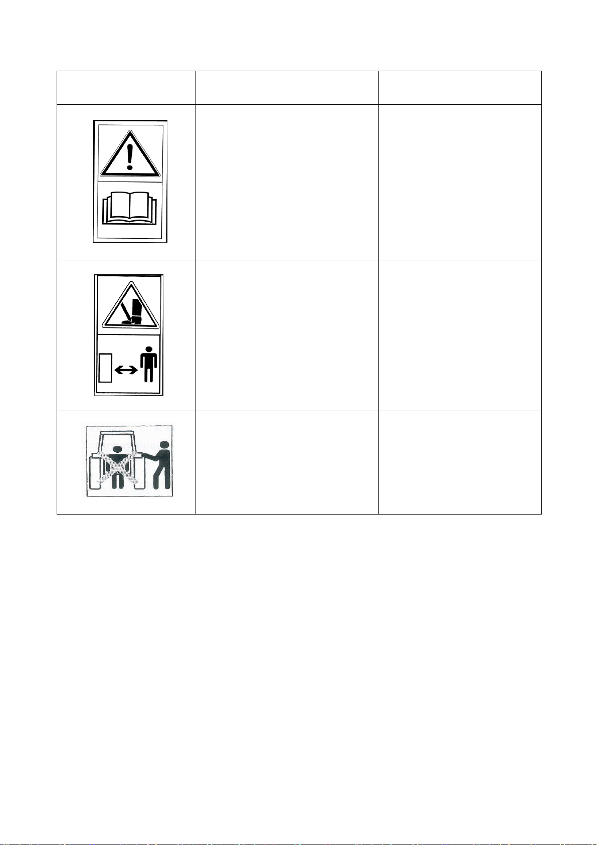
Table 1. Information and warning signs
Safety sign
Meaning of the safety mark
Place the sign is located on
the machine
Read the operating instructions
before using this machinery
The subsoiler frame near the
top connection fixing point
Risk of toes or feet being crushed
The subsoiler frame near the
top connection fixing point
Do not stand too close to hoists
while the lift is being operated
The subsoiler frame near the
top connection fixing point
2. Intended purpose of the subsoiler
The MGP subsoiler is an agricultural machine intended for loosening the soil,
especially the destruction of the plough sole, and airing of the soil (at the depth from 20 to
60 cm) without disturbing its layered structure. As a result, its physical and biological
properties are improved, especially in case of heavy, catchment soils. Aeration and
improvement of the water and air circulation in the soil profile obtained through the use of a
subsoiler ensures an excellent agrotechnical effect. The MGP subsoiler is designed to work
with active machinery. It is equipped with a three-point suspension system and a frame
structure that does not interfere with the WOM shaft, allowing a two-layer cultivation of the
soil. This also ensures comprehensive cultivation for plants that have particular soil
structure requirements (potatoes, sugar beet).

6
WARNING! The subsoiler is intended exclusively for agricultural work. Use for other purposes will
be construed as improper use and will result in loss of warranty. Failure to comply with these
operating instructions will also be construed as misuse.
WARNING! The manufacturer is not responsible for damage caused by misuse of the machine.
3. Safe operation
The subsoiler can only be handled and operated by adults who are familiar with the
operating instructions and take all necessary precautions and in particular:
when transporting the subsoiler on public roads, the following must absolutely be
mounted on the machinery’s frame:
◦a distinctive plate for slow-moving vehicles according to PN-93/R-36154
◦a portable warning light device that includes two / forward-facing and backward
facing warning signs / with white driving lights facing forward and rear light
clusters and backward facing reflective discs.
special care is to be taken when overtaking and passing other vehicles,
while the subsoiler is in operation do not use the tractor independent brakes,
all operations on the machine must be performed only when the tractor’s engine is
switched off and the machine is lowered to the ground,
do not approach the subsoiler when it is being lifted or lowered,
do not come between the tractor and the attached subsoiler while the engine is
running,
do not reverse the subsoiler or make turns when the machine is lowered into its
operating position,
do not stand on the machine or add any extra loads during operation or while it is
standing idle,
use only factory supplied bolts and cotter pins for safe connection of the subsoiler
with the tractor,
all repairs, inspections, maintenance or cleaning of working parts shall be carried out
only when the tractor engine is switched off and after having lowered the subsoiler to
the ground,
turn off the engine before leaving the tractor,
the subsoiler may only be disconnected from the tractor on a level surface ensuring
a stable stop,

7
the subsoiler should be parked in an area out of the reach of the farm animals,
use and operation of the machine by children or persons unfamiliar with the
instructions or under the influence of alcohol is prohibited.
WARNING! Failure to follow the above rules may present a risk to the operator and any third
parties, as well as damage to the machine. The user is responsible for any damage resulting from
non-compliance.
4. General information on the subsoiler operation
The main frame of the subsoiler constitutes the basic support element for the entire
machine. Six tines are attached to the subsoiler frame (6 pieces). Subsoilers can be
equipped with support wheels, which serve to adjust and maintain the depth of the
subsoiler’s operation.
4.1 Subsoiler adjustment
The subsoiler is delivered for sale in ready-to-use condition. Due to the limitations of
transportation, it may also be delivered in a partially disassembled condition - most often
this involves disengaging the support wheels from the MGP subsoiler.
The subsoiler should be protected against overturning by properly adjusted support legs
(these are standard equipment of the subsoiler).
During operation the machine is subject to adjustment of the following:
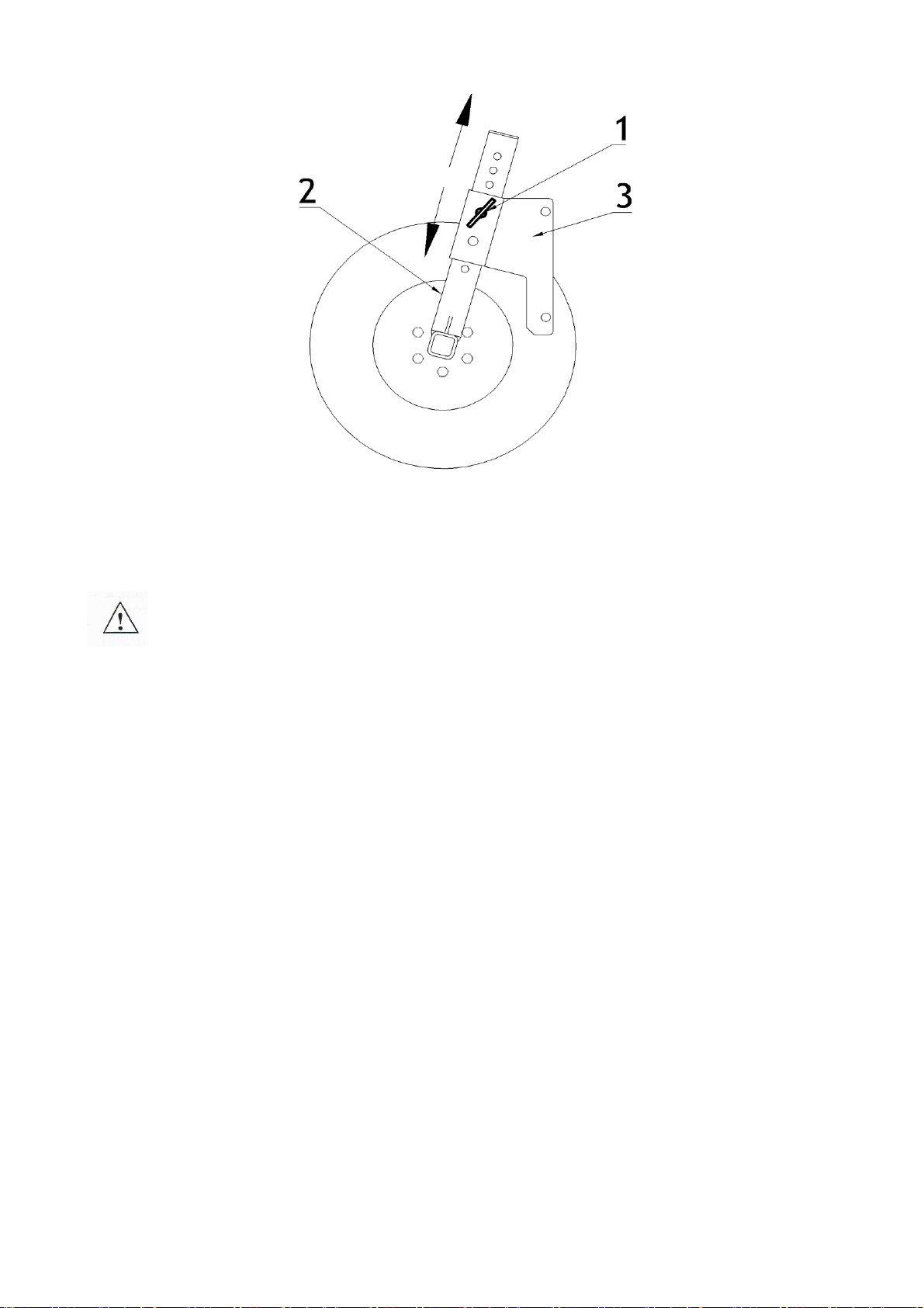
depth of the tines’ operation - by adjusting the position of the support wheels in the
adjustment brackets (fig. 1),
depth of the tines’ operation relative to the machine used with it - by setting the
three-point hitch depth with the appropriate adjustment opening.
8
Figure 1. Adjustment of operation depth by means of the wheel on the subsoiler: 1 - depth
adjustment bolt; 2 - bar with openings in the support wheel; 3 - support wheel bar handle.
WARNING! Prior to working with the subsoiler, check all bolted connections and ensure the
machine is properly connected to the tractor.
4.2 Working with the subsoiler
Prior to working with the subsoiler, it should be hooked up to the tractor's three-point hitch,
and for this purpose the operator must:
remove the lower coupling bolts,
carefully reverse the tractor and attach the coupling bolts to the tractor's lower rod,
and then secure them with their cotter pins,
connect the tractor’s upper rod,
check the lifting and lowering of the subsoiler.
In order to attach the machine cooperating with the MGP subsoiler the operator must:
adjust the distance between the rod hooks and the ground so that they are located
below the rod pins of the co-operating machine, by means of the pins, placing these
above the depth-setting bar (Figure 2)
carefully reverse the tractor along with the subsoiler to meet up with the co-operating
machine,
raise the coupling hooks so that they engage with the pins,
lock the coupling hooks on the bolts,
connect the upper rod to the co-operating machine.

9
Upper connector
Depth adjustment
Bolt
Setting bar
Three-point hitch tension rod
Figure 2. MGP subsoiler three-point hitch components
WARNING! Coupling of the tractor with the subsoiler must be carried out carefully, at the tractor’s
minimum speed! When hooking up the machine, make sure there are no bystanders too close.
Before leaving for the field via a public road, a warning sign must be attached to the
subsoiler or the co-operating machine, for transport on public roads.
The subsoiler can be operated at the speed of 8 km/h.
WARNING! Failure to keep to the above speed may result in a malfunction or accident.
When properly hooked up, the subsoiler should, while working, move evenly behind the
tractor and uniformly loosen the soil over its entire working width. The subsoiler’s frame
should be horizontal to the field’s surface (by adjusting the upper rod of the tractor).
The hydraulics of the tractor should be set for position adjustment, but under unfavourable
conditions one may use powered adjustment or mixed adjustment.

10
The subsoiler’s proper operating depth is determined by adjusting the position of the bolts
in the openings of the adjustable support wheels (Figure 1). The depth relative to the co-
operating machine is determined by means of the depth adjustment bolts by inserting them
into the appropriate opening below the depth-setting bar (Figure 2).
WARNING! Maximum operating depth of the subsoiler is 600mm. Exceeding this parameter may
cause a malfunction or accident.
WARNING! The subsoiler must not be used on extremely stony soil, as this may cause damage to
the working parts of the machine or an accident.
5. Faults and abnormalities in the subsoiler operation
In order to extend the machine’s working life, all instructions in this manual must be
observed as regards the operation, adjustment, lubrication, transport and storage of the
machine.
WARNING! Any adjustments, repairs, or removal of blockages should only be carried out with the
subsoiler lowered onto the ground. The tractor’s engine must be switched off.
WARNING! The subsoiler must not be used on soil that is too damp, as this results in degradation
of the soil structure, or on stony ground with rocks of any considerable size!
6. Maintenance
On finishing each job (following at least every 10 hours), the subsoiler should be
cleaned of all soil and all connections and assemblies should be checked. Loosened bolted
joints are to be tightened. Damaged or worn parts should be replaced with new or
regenerated parts.
WARNING! During any maintenance work the shaft must rest on the ground and the tractor’s
engine must be turned off.
7. Storage
After the season has ended, you should check all parts and assemblies. In the event
of damage or significant wear, replace appropriate parts with the new ones. Clean the
painted surfaces of all dirt and paint any rusted areas with anti-corrosion paint and then add
a topcoat. Protect the working surfaces of the tines and the tubular shaft from corrosion.

11
WARNING! Store the subsoiler on a level, horizontal surface, preferably indoor or in a roofed area
protected from unauthorized access by outsiders or animals.
8. Transport
9.
WARNING! Particular caution should be exercised when transporting the subsoiler. It is forbidden
to travel on public roads without an appropriate additional warning sign.
Prior to travel on a public road, a portable warning light device and a distinctive sign for
slow-moving vehicles should be fitted to the ends of the subsoiler’s frame.
The portable warning light device should consist of two panels in red and white stripes,
equipped with:
at the front - white driving lights, and a reflective white circle,
at the rear - red driving lights, brake lights, indicators and a reflective red triangle.
A distinctive plate (a triangle) should be affixed in the middle of the frame.
During transport, the subsoiler should be raised to such a height that the minimum
clearance under the machine is at least 25 cm.
The transport speed must not exceed:
20 km/h –on asphalt roads
5 km/h –on roads with any other surface
When towing the subsoiler, drive the tractor as close to the right edge of the road as
possible. Use caution when overtaking and passing other road users.
REMEMBER! Travel on public roads without the required traffic signs, warning signs and lighting
may cause an accident!
REMEMBER! Warning light devices are not factory fitted to the subsoiler. They can be purchased
at any agricultural machinery sales outlet.
10. Dismantling and scrapping the subsoiler
Dismantling and scrapping of a used subsoiler does not pose any great threat to the
environment. Dismantling the subsoiler should start with the removal of the small parts
(bolts, screws, etc.) then going on to the larger ones. The dismantled subsoiler should be
sent to a scrap metal recycling centre as a recyclable material.

12
11. Technical characteristics
Table 2. Technical data for the MGP subsoiler
Type
Working width
[m]
Secured by
Number of
tines
[pcs]
Min. power
[KM]
Weight
[kg]
MGP 6 3000
3.00
Cotter pin
6
190
995
13
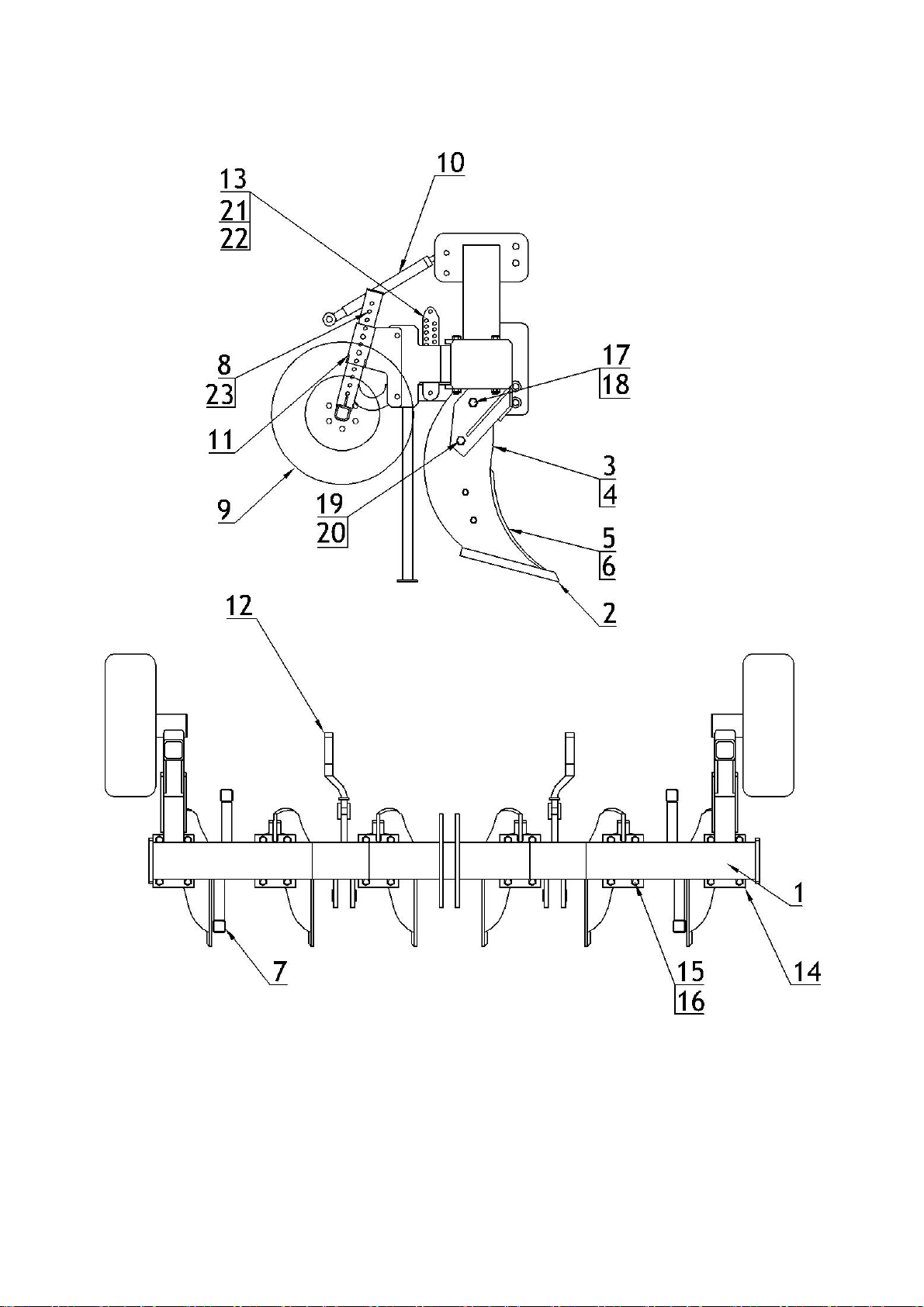
12.Spare parts list
Figure 2 Subsoiler MGP 6 3000 - spare parts

14
Table 3. List of spare parts for the MGP subsoiler
Item
N
ame
MGP 6 3000
1
Frame
1
2
Double sided coulter
6
3
Right-hand tine
3
4
Left-hand tine
3
5
Right-hand moldboard
3
6
Left-hand moldboard
3
7
Support leg
4
8
Frame with front axle (optional)
2
9
Support wheel (optional)
2
10
Turnbuckle
1
11
Handle of the arm with front axle
2
12
Band with three-point hitch hook
2
13
Height adjuster
2
14
Tine holder
6
15
M24x270-10.9
)
bolt
24
16
M24
(self-locking) nut
24
17
M30x90-10.9 bolt
6
18
M30
(self-locking) nut
6
19
M16x90-10.9 bolt
6
20
M16
(self-locking) nut
6
21
M20x80-8.8 bolt
4
22
M20
(self-locking) nut
4
23
Pin
2

15
4 General rules governing the warranty procedure
•Only original spare parts intended for Mandam machinery provide long-lasting
and efficient operation. Parts for all Mandam machinery are available through
our dealer network or directly from the manufacturer.
•The warranty covers defects and damage attributable to the Manufacturer as a result
of material defect, inappropriate treatment or assembly. By granting a warranty, the
Manufacturer agrees (the scope and total costs of repairs must be agreed between
the Manufacturer and the other party) to the following:
a) free repair of equipment found to be faulty,
b) provide the User with new properly manufactured replacement parts free of
charge,
c) cover labour and transport costs.
•Complete replacement of the equipment with another unit free of defects, should the
operations listed in a) and b) fail to ensure proper operation of the equipment.
•Warranty services are to be provided by the Manufacturer, or by the warranty
services contractor appointed by the Manufacturer.
•The User should report a complaint promptly and within 14 days of the occurrence of
the fault or damage.
•The warranty is automatically to be extended for the period during which the
equipment is repaired.
•The Manufacturer shall not accept any warranty claim if the equipment has
undergone any technological modifications or repair without the Manufacturer’s prior
knowledge, has been improperly stored, maintained or improperly used.
•If the User considers that the complaint they have made has not been properly
handled, they have the right to demand that the Seller has the case examined by an
expert appointed by both parties to the dispute.

16
P.P.H. MANDAM Sp. z o.o.
44-100 Gliwice ul.Toruńska 2
e-mail mandam@mandam.com.pl
Tel.: 032 232 26 60 Fax: 032 232 58 85
NIP: 648 000 16 74 REGON: P –008173131
WARRANTY CARD
ORKAN VARIO plough
Type ......................................
Serial number ......................................
Year of manufacture ......................................
Sale date ......................................
The guarantee is valid for 12 months from the date of sale.
Warranty services on behalf of the equipment’s manufacturer is to be performed by
............................................................................................................
(to be filled in by the seller)
.......................................
........................................
(Manufacturer's stamp) (Seller’s stamp)
The warranty card must be shown when submitting a claim
This manual suits for next models
1
Table of contents
Other Mandam Farm Equipment manuals

Mandam
Mandam GAL-K User manual

Mandam
Mandam KNIFE ROLLER 3.0 User manual

Mandam
Mandam Hybro 3,0 User manual

Mandam
Mandam MBS User manual

Mandam
Mandam RHINO User manual

Mandam
Mandam SPEC HD 2,5 User manual

Mandam
Mandam ORKAN VARIO Series User manual

Mandam
Mandam MGX 2200 User manual

Mandam
Mandam ORKAN 3+ User manual

Mandam
Mandam MWC Series User manual


