SERAD IMD 20 Series User manual

IMD20-GI-2101-EN
Digital DRIVE for Brushless motor
IMD 20 Series
Read manual before installing and respect
all indications with this icon:
INSTALLATION
GUIDE


IMD 20 Drive installation guide
R2101 - 3 -
SERAD S.A
Table of Contents
1-
Introduction................................................................................... 4
1-1- Warning...................................................................................... 4
1-2- MD series drive description....................................................... 5
2-
Installation..................................................................................... 7
2-1- General....................................................................................... 7
2-2- Front view................................................................................... 8
2-3- Top view...................................................................................... 9
2-4- Bottom view.............................................................................. 10
2-5- Mounting................................................................................... 11
2-6- Connector pin assignments ...................................................... 12
2-7- Cables....................................................................................... 23
2-8- Connection diagrams / Protections.......................................... 24
2-9- Stand-alone drive ..................................................................... 25
2-10- Drive controlled by a motion controller................................ 26
2-11- Connecting a motor brake...................................................... 27
2-12- System checks before starting ................................................ 27
2-13- STATUS DISPLAY.................................................................. 28
2-14- Error messages: ..................................................................... 31
IMD 20 Drive installation guide
R2101 - 4 -
SERAD S.A
1- Introduction
1-1- Warning
Read this manual before first installing, nonobservance may result in property
damages and in personal injuries.
Only suitable qualified personnel should undertake the mounting, installation,
operation and maintenance of the equipment must be complied with the general setup
and safety regulations for work on power installations (e.g. DIN, VDE, EN, IEC or
other national and international regulations).
It is important that all safety instructions are strictly followed. Personal injury can
result from a poor understanding of the safety requirements.
The following safety regulations should be followed:
•
VDE 0100
Specification for the installation of power systems
up to 1000 V
•
VDE 0113
Electrical equipment of machines
•
VDE 0160
Equipment for power systems containing electronic
components.
-Never open the equipment.
-Dangerous high voltages exist within the equipment and on the connectors.
Because of this, before removing any of the connectors, it is necessary to remove
the power and wait at least 5 minutes to allow the capacitors to discharge.
-Never connect or disconnect the drive with power applied.
-Some of the drive’s surfaces can be very hot.
Some of the drive's components are susceptible to damage from electrostatic
discharges. Always handle the equipment using appropriate anti-static precautions.
We have gone to great lengths to ensure this documentation is correct and complete. However, since it
is not possible to produce an absolutely error-free text. No responsibility will be assumed by SERAD
for all damages caused by using this documentation and software.
We reserve the right to make changes to all or part of the specification without prior notice.

IMD 20 Drive installation guide
R2101 - 5 -
SERAD S.A
1-2- MD series drive description
Supply : 230V to 400V AC ±10% three phase
Auxiliary supply : 24 V DC ±10%, 0.5A typical (0,8A max if all options)
Supply filter : Integral
Switching frequency : 6.67 kHz sine-wave PWM
DC bus voltage : 310V to 680V
Braking resistance :
Integral : 33 ohms 60W
Possibility to add an external resistor :
Min value Max. cont. power Imp power
26Ω10KΩ20KΩ
Protection :
Short circuit between phases, phase to earth, over current, I2t
Over voltage, under voltage
Motor feedback fault
Motor feedback : Resolver
SinCos encoder Hiperface
(option)
Master encoder :
Incremental encoger
Absolute encoder SSI
SinCos encoder Hiperface
(option)
Virtual
Encoder emulation : Incremental : A, /A, B, /B, Z, /Z 1 to 100 000 points per rev
Diagnostic : STATUS display
Communication :
RS 232 MODBUS RTU
RS 422
(option)
, RS 485 MODBUS RTU
(option)
EtherCAT
(option)
CANopen
(option)
Digital inputs :
4 inputs (with 2 fast inputs I3 and I4)
12 additional inputs with expansion module (with 2 fast inputs I15 and I16)
Type: PNP, 24V DC, 8mA per input and 15 per fast input
Logic 0: Between 0 and 5 V
Logic 1: Between 8 and 30 V
Digital outputs :
2 outputs as standard
S1 : Relay, 48V dc / 48V ac, 3A max
S2 : NPN (open collector) 24V dc, 100mA
8 additional outputs with expansion module
Type : PNP 24V dc, 500mA max per output
Protected against short circuit and over temperature.
Analogue inputs :
2 inputs :
Input voltage : ±10 V
Maximum voltage : ±12 V
Input impedance : 20 Kohms
Resolution : 16 bits for input 1 and 12 bits for input 2
Analogue output :
1 output :
Output voltage : ±10 V
Maximum current : 5 mA
Resolution : 8 bits, bandwidth 20Hz
IMD 20 Drive installation guide
R2101 - 6 -
SERAD S.A
Architecture :
Processor :150 MHz DSP and 100 000 gates FPGA
FLASH memory for programs and parameters
RAM memory for data
FRAM memory for variables
Real-time, multi-tasking kernel
Control loops :
Current loop : 75 µs
Speed loop : 150 µs
Position loop : 150µs
Operating modes :
Torque mode
Speed mode
Position mode
Stepper Mode (pulse input, direction)
Motion functions (absolute, relative and infinite movements, S profile)
Advanced motion functions (gearbox, CAM profiles, CAMBOX functions, triggered movement)
Operating temperature : 0 to 40°C
Storage temperature : -10 to 70°C
Degree of protection : IP 20
Weight 6,4 Kg
Drive Rated current Peak current ( 2s ) Rated power Dimensions w x h x d
IMD / 2
0
2
0 Aeff
4
0 Aeff
11
,
2
kVA
72 x 293 x 233

IMD 20 Drive installation guide
R2101 - 7 -
SERAD S.A
2- Installation
2-1- General
It is very important to adhere to the following:
A badly earthed connection can damage electronic drive components.
The drive must be installed vertically in free air to ensure cooling by natural
convection.
It must be protected from excess humidity, liquids, and dirt.
The motor, resolver and encoder cables must be screened, the screen being earthed
at both ends of the cable.
The analogue I/O must use screened cable, the screen being earthed at one end
only.
The cable for the RS 232 serial link between the drive and the PC must be screened,
the screen being earthed at both ends of the cable. It should be disconnected from the
drive when no longer in use. All of these cables, as well as the I/O cables, should be
run separately from the power cables.
Diodes must be fitted across the loads on all static digital outputs (Q2 to Q10).
These diodes must be positioned as close to the load as possible. The supply and
signal cables must be free from over-voltage transients.
Safety standards specify a manual reset after a stop caused either by a supply
interruption, or by an emergency stop or by a drive fault.
For all serious faults, it is obligatory to remove the high voltage supply to the drive.
The Drive Ready output should be connected in series in the emergency stop loop.
In the case of axis over-travel, the over-travel limit switches must be connected to
the limit inputs or in series with the emergency stop loop. It is also recommended to
use the software limits.
If the drive is configured in speed loop, the drive enable input should be controlled
by the supervisory controller (CNC, PLC etc).
If the drive is configured in position loop, the parameter "Maximum following
error" should be set appropriately.
If the drive contains an application program developed using iDPL, connect a
signal ‘Cabinet supplies OK’ to one of the digital inputs and monitor it in a non-
blocking safety task. On detection of an excess following error the drive will be put in
open loop mode and the drive ready relay will be opened. If another action is required
you should use the SECURITY instruction.
IMD 20 Drive installation guide
R2101 - 8 -
SERAD S.A
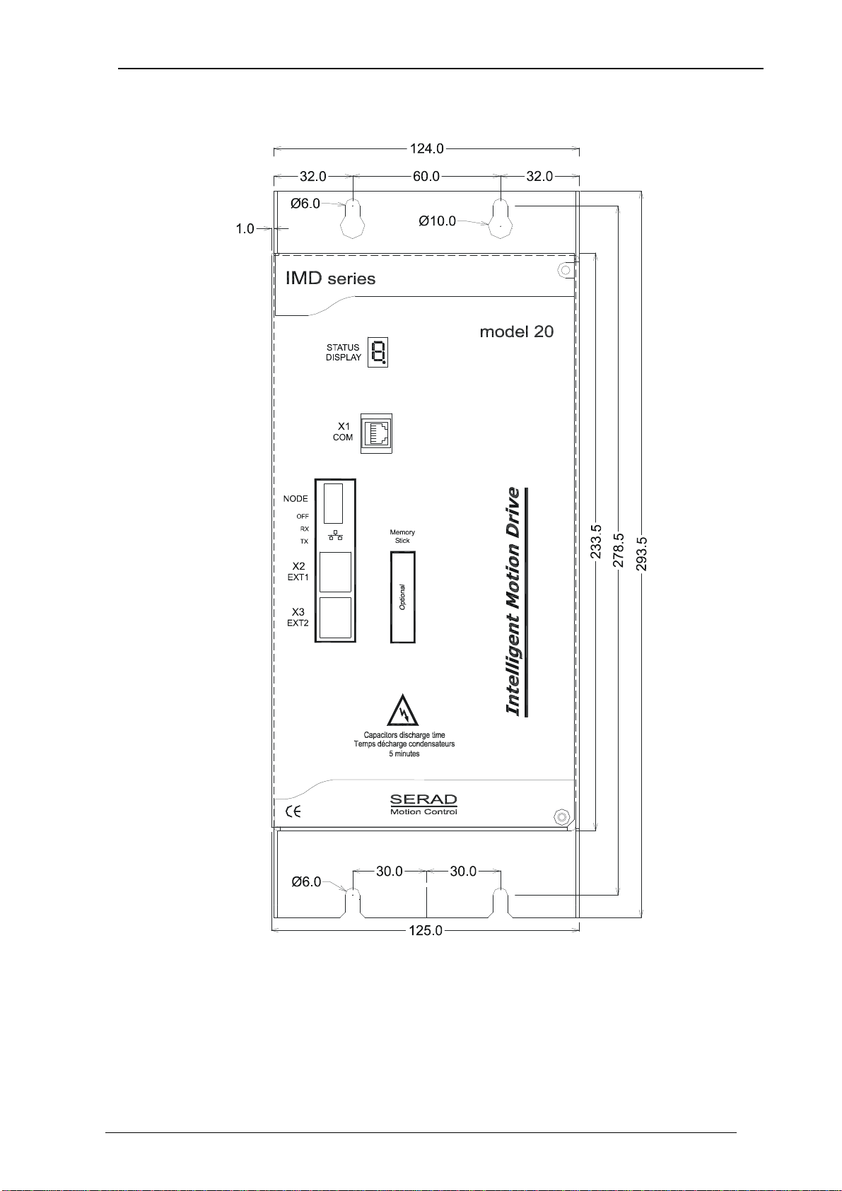
2-2- Front view
STATUS 7-segment diagnostic display
X1 COM RS-232 serial port for communication with a PC
X2 EXT1 Extension: Optional communications ports
X3 EXT2 Extension: Optional communications ports

IMD 20 Drive installation guide
R2101 - 9 -
SERAD S.A
2-3- Top view
X4 ENCODER OUTPUT Multifunction encoder output
X5 ENCODER INPUT Multifunction encoder input
X6 24Vdc Auxiliary 24V DC supply
X7 I/O Digital I/O
X8 POWER SUPPLY Single / Three-phase power supply
X9 EXT I/O Option: I/O expansion board
X SAFE Option : Secure input
The voltage on connector X8 can reach 480V!
X - SAFE
IMD 20 Drive installation guide
R2101 - 10 -
SERAD S.A
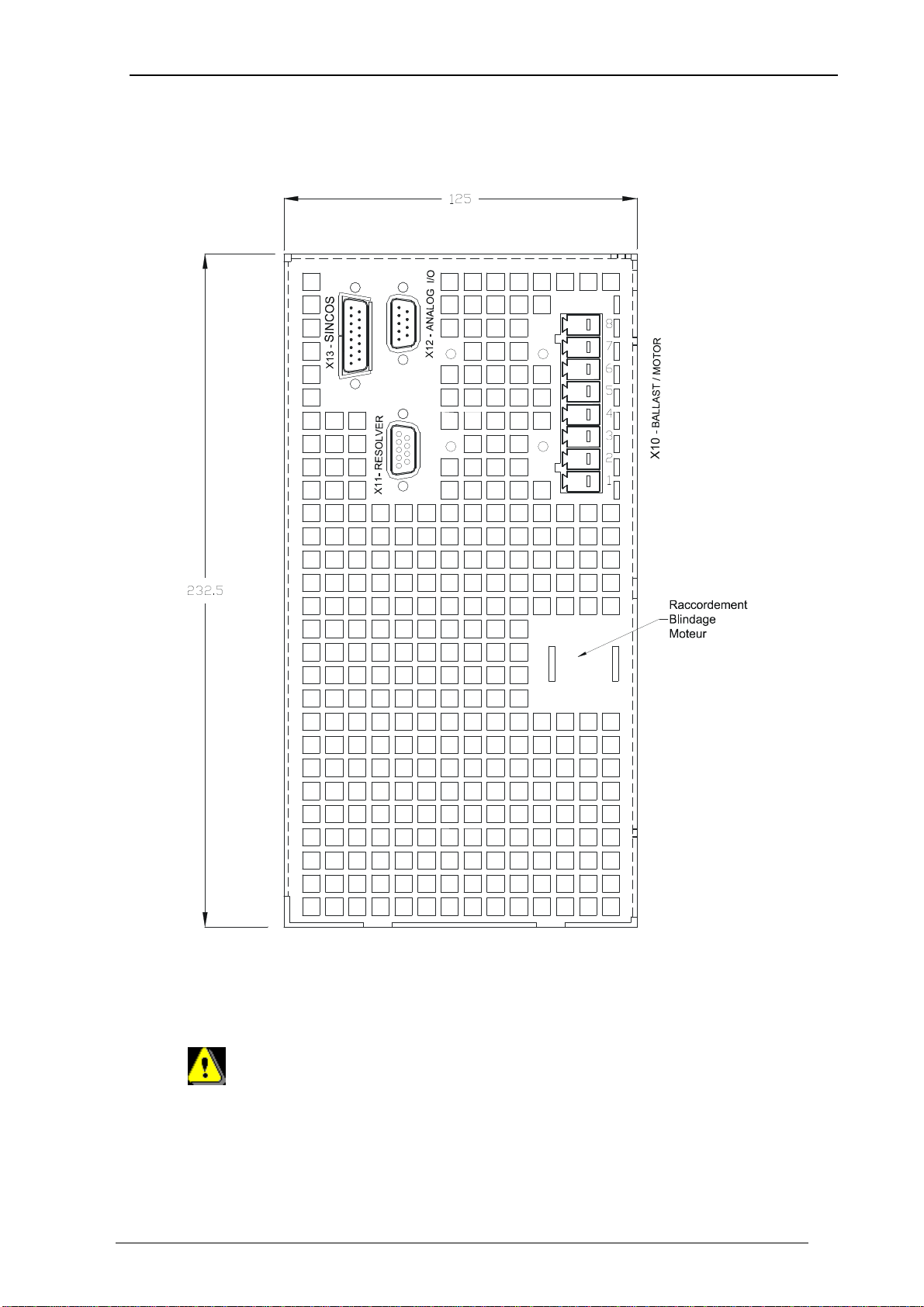
2-4- Bottom view
X10 RB / MOTOR External braking resistor and motor supply
X11 FEEDBACK Motor position feedback (resolver / encoder)
X12 ANALOG Analogues I/O
X 13 SINCOS Motor position feedbacks (if SINCOS encoder is used)
Care must be taken when making connection to connector X10. An incorrect
connection can seriously damage the drive. Dangerous voltages are present on
X10 (900V).
Wait at least 5 minutes to allow the capacitors to discharge before remove
connector.

IMD 20 Drive installation guide
R2101 - 11 -
SERAD S.A
2-5- Mounting
Several drives can be mounted side-by-side provided that enough space (at least 20
mm) is left to ensure good natural convection. Let a space greater than 90 cm over and
under drives to allow for the various connectors and cables to be fitted

IMD 20 Drive installation guide
R2101 - 12 -
SERAD S.A
2-6- Connector pin assignments
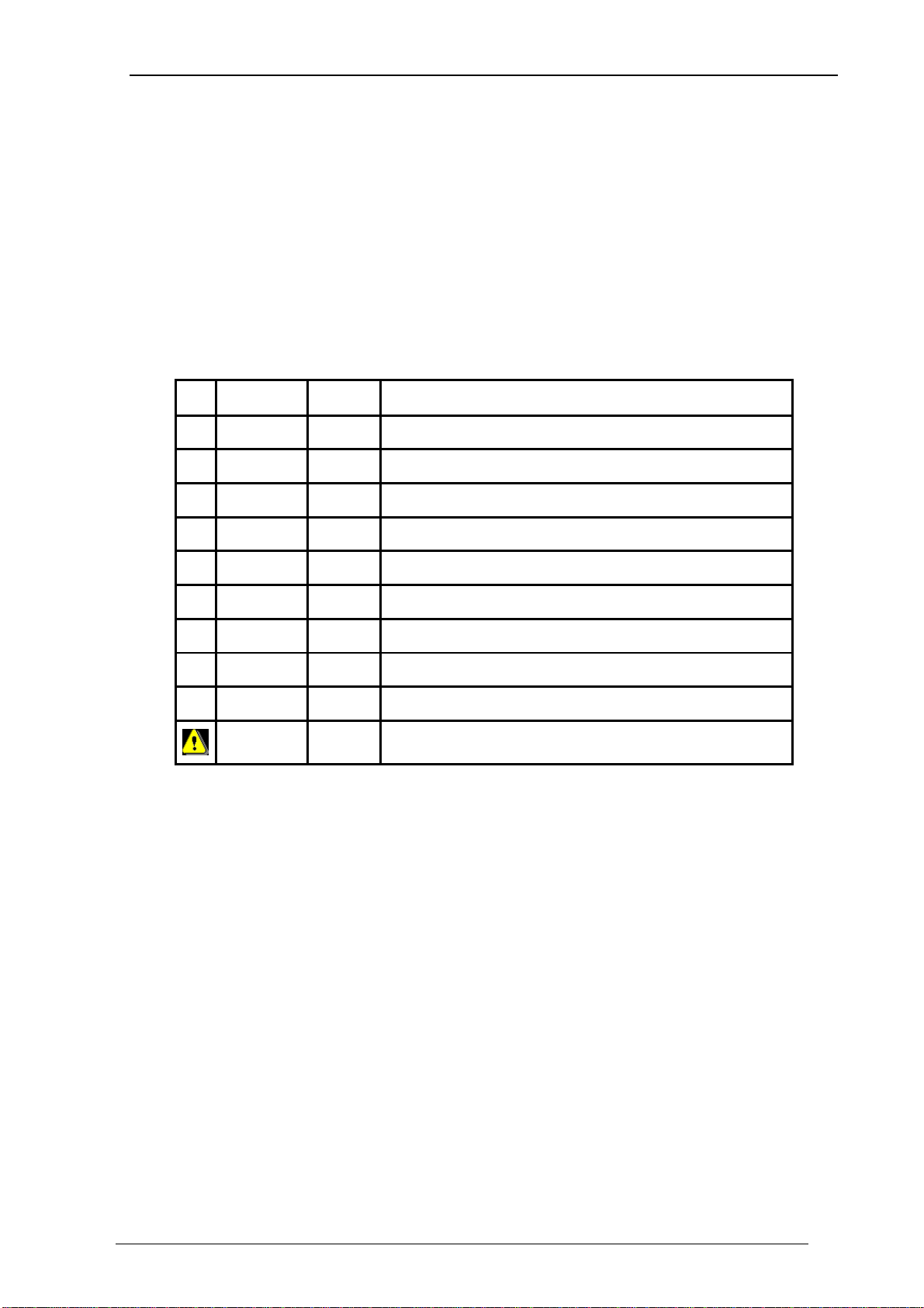
X1: RJ45 serial port for downloading programs and parameters.
N° Name Type Description
1
2 RXD Inp Receive data
3 TXD Out Transmit data
4
5 GND 0V
6
7
8 CTS Inp Clear to send
SHIELD Connect the shield to the shell of the connector
In the iDPL software, the RS232 communication is established when the icon in the
bottom left side is in this fixed state :
If the connection is not stable (state icon connected/disconnected), check if the cable
and the USB-serial converter are certified by SERAD. Otherwise please contact our
technical department.
3-TXD
2-RXD
5-GND
7
8-CTS
6
4
1

IMD 20 Drive installation guide
R2101 - 13 -
SERAD S.A
X2 & X3: Extension: Optional communications port
•X2 and X3 are identical and have the same connection. They make easier drive
network connection.
•For the TCP module, refer to the documentation TCP option installation guide
available on www.serad.fr
•Node Address : For RS422, RS485 and CANopen, the NodeID corresponds to the
five firstly dipswitchs + 1
Ex:
For the RS422, RS485 and CANopen module, the terminal resistor is activated by the dip
switch n°6 (120
Ω
).
In CANopen, do not use the Node ID n° 1 if you have a multi drive project.
RS232 communication allows communication with only 1 device (ex: 1 PLC
and 1 IMD drive).
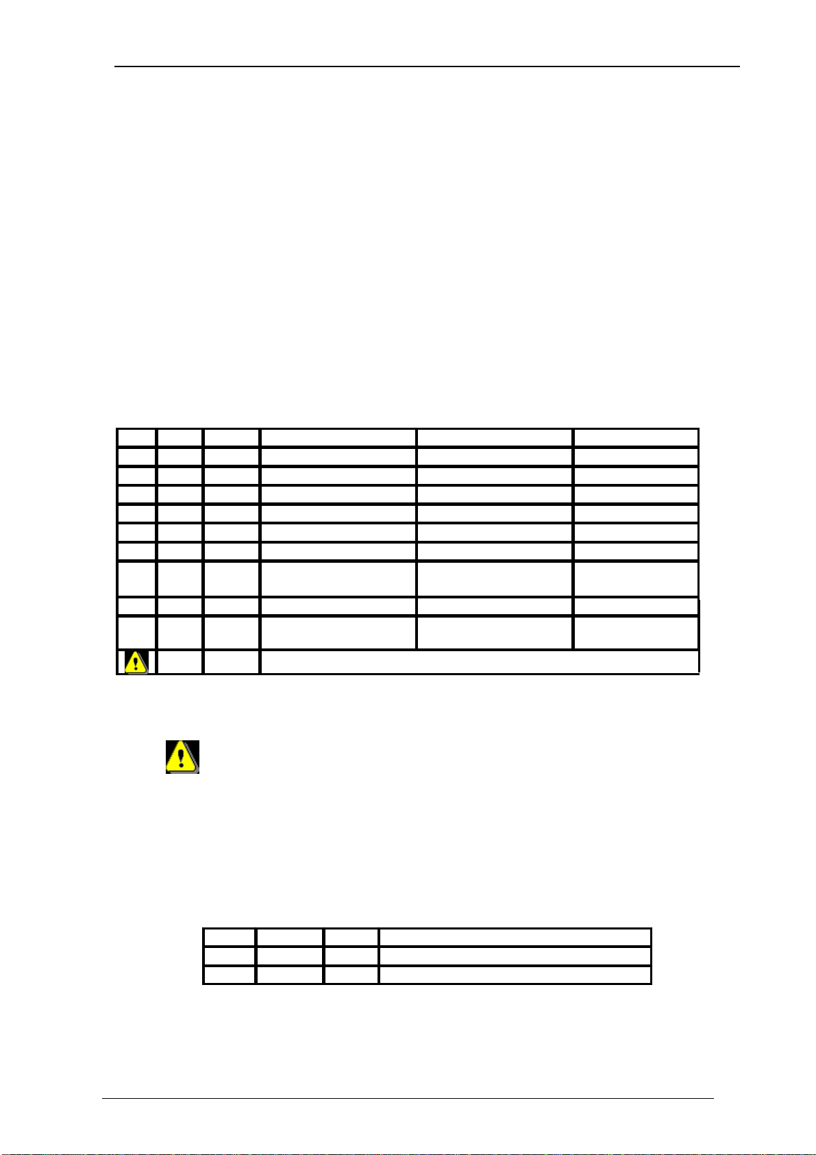
N° Module RS 232
Module RS 422 Module RS 485 Module CANopen
Module EtherCAT
Module TCP
1 TD + TD +
2 RXD RX+ TD - TD -
3 TXD RX- RD + RD +
4
5 GND GND GND GND
6 RD - RD -
7 TX- TRX- CAN_L
8 TX+ TRX+ CAN_H
Connect the shield to the shell of the connector

IMD 20 Drive installation guide
R2101 - 14 -
SERAD S.A
•Node Address : For RS422, RS485 and CANopen, the NodeID corresponds to the
six firstly dipswitchs + 1
Ex:
IMD 20 Drive installation guide
R2101 - 15 -
SERAD S.A
X4: Multifunction encoder output:
•Encoder emulation output
The choice of the number of points is made from the iDPL software.
Connector : SUBD 9 way female
NC (Not connected): It is forbidden to connect this pins.
N° Name Type Encoder emulation
1 A Out Channel A
2 /A Out Channel A inverted
3 B Out Channel B
4 /B Out Channel B inverted
5 Z Out Channel Z
6 /Z Out Channel Z inverted
7
8 GND 0V
9
SHIELD Connect the shield to the shell of the connector
IMD 20 Drive installation guide
R2101 - 16 -
SERAD S.A
X5: Multifunction encoder input:
•Incremental encoder input
•SSI encoder input
•Stepper input
The choice of the input is made in iDPL software in the Multifunction encoder input
windows
5V TTL encoder (0-5V, differential)
Connector : SUBD 9 way male
* If the feedback is SINCOS then don’t use 5V powersupply (pin 7 of connector X5)
but an external powersupply.
NC (Not connected): It is forbidden to connect this pins.
X6: 24V dc supply
Connector: Removable 2 ways, 5.08mm pitch
N° Name Type Description
1 XGND 0V
2 24Vdc Inp Control card supply, backup motor position
N° Name Type Incremental encoder Codeur SSI Stepper
1 A Inp
Channel A
Data Direction
2 /A Inp
Channel A inverted
/Data /Direction
3 B Inp
Channel B
NC Pulse
4 /B Inp
Channel B inverted
NC /Pulse
5 Z I/O
Zero marker
Clock NC
6 /Z I/O
Zero marker inverted
/Clock NC
7 +5Vdc Out
Supply for external
encoder, 100 mA max.*
NC NC
8 GND
0V
0V 0V
9 Inp NC SSI selection : Connect
pins 8 and 9 NC
SHIELD
Connect the shield to the shell of the connector
IMD 20 Drive installation guide
R2101 - 17 -
SERAD S.A
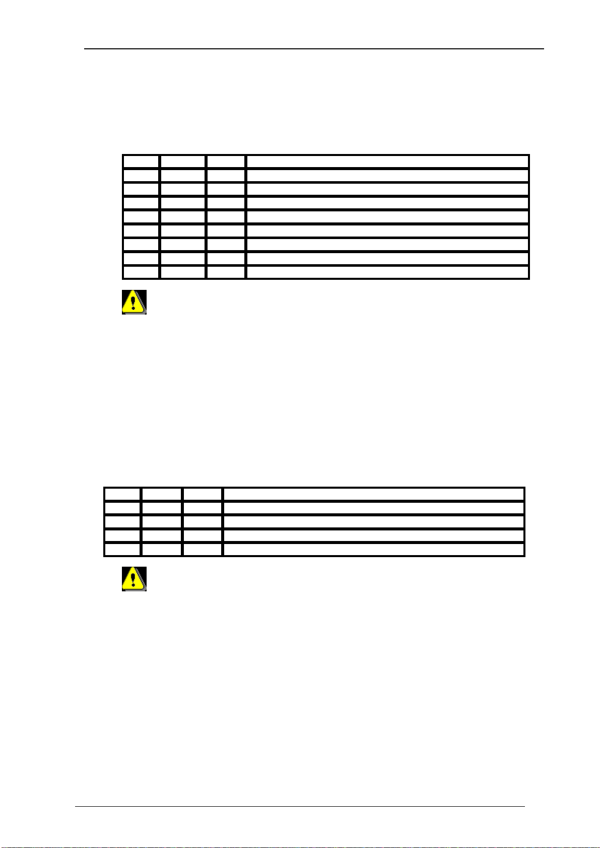
X7: Digital I/O
Connector: Removable 8 ways, 3.81mm pitch
N° Name Type Description
1 Q2 Out Output 2, programmable : type NPN, 24 Vdc, 100mA
2 Q1 Out Output 1, programmable : standard function DRIVE READY
3 Q1 Relay contact, N/O between terminals 2 and 3
4 DGND 0V digital I/O
5 I4 Inp Input 4, programmable
6 I3 Inp Input 3, programmable
7 I2 Inp Input 2, programmable
8 I1 Inp Input 1, programmable:standard function ENABLE
The output Q2 is NPN open collector: the load must be connected between
Q2 and +24V DC.
X8: High voltage supply
Connector: Removable 4 ways, 7.62mm pitch
N° Name Type Description
1 PE Supply earth
2 L1 Inp Supply L1 for 400V
3 L2 Inp Supply L2 for 400V
4 L3 Inp Supply L3 for 400V
Care must be taken when making connection to connector X8.
Wait at least 5 minutes to allow the capacitors to discharge before remove connector.
The armoured motor cable must arrive directly on the terminals of the drive.
Connect the shield (on drive side) to the srew provided (see Front view of the drive).

IMD 20 Drive installation guide
R2101 - 18 -
SERAD S.A
X9: Option: Expansion module, 12 inputs / 8 outputs
Connector: SUBD 25 way female
N° Name Type Description
1 I5 Inp
Input 5, programmable
2 I6 Inp
Input 6, programmable
3 I7 Inp
Input 7, programmable
4 I8 Inp
Input 8, programmable
5 I9 Inp
Input 9, programmable
6 I10 Inp
Input 10, programmable
7 IOGND*
0V digital I/O
8 Q3 Out
Output 3, programmable
9 Q4 Out
Output 4, programmable
10 Q5 Out
Output 5, programmable
11 Q6 Out
Output 6, programmable
12 IO 24Vdc** Inp
External supply, 24 V dc
13 IO 24Vdc** Inp
External supply, 24 V dc
14 I11 Inp
Input 11, programmable
15 I12 Inp
Input 12, programmable
16 I13 Inp
Input 13, programmable
17 I14 Inp
Input 14, programmable
18 I15 Inp
Input 15, programmable
19 I16 Inp
Input 16, programmable
20 Q7 Out
Output 7, programmable
21 Q8 Out
Output 8, programmable
22 Q9 Out
Output 9, programmable
23 Q10 Out
Output 10, programmable
24 IOGND*
0V digital I/O
25 IOGND*
0V digital I/O
SHIELD
Connect the shield to the shell of the connector
* Pins 7, 24, 25: internal connection
** Pins 12, 13: internal connection

IMD 20 Drive installation guide
R2101 - 19 -
SERAD S.A
X10: Motor armature
Connector: Removable 8 ways, 7.62mm pitch
N° Name Type Description
1 RI Internal braking resistor *
2 RB Braking resistor *
3 DC Bus + Out DC bus +
4 DC Bus - Out DC bus -
5 PE Motor earth
6 W Out Motor phase W
7 V Out Motor phase V
8 U Out Motor phase U
The armoured motor cable must arrive directly on the terminals of the drive.
Connect the shield (on drive side) to the srew provided (see Front view of the drive).
*Selection of the braking resistor:
- Internal resistor: Fit a link between terminals 1 and 2
- External resistor: Remove the link between terminals 1 and 2
Connect the external resistor between terminals 2 and 3
Care must be taken when making connection to connector X10. An
incorrect connection can seriously damage the drive. Dangerous voltages are
present on X10.
SERAD MOTOR
C
A
1
4
B
D
3
Shield reverse
around the ring
1
4
3
2
C
Phase U
D
Phase V
Phase W
Earth
Break +
Break -
DESCRIPTION
IMD 20 Drive installation guide
R2101 - 20 -
SERAD S.A
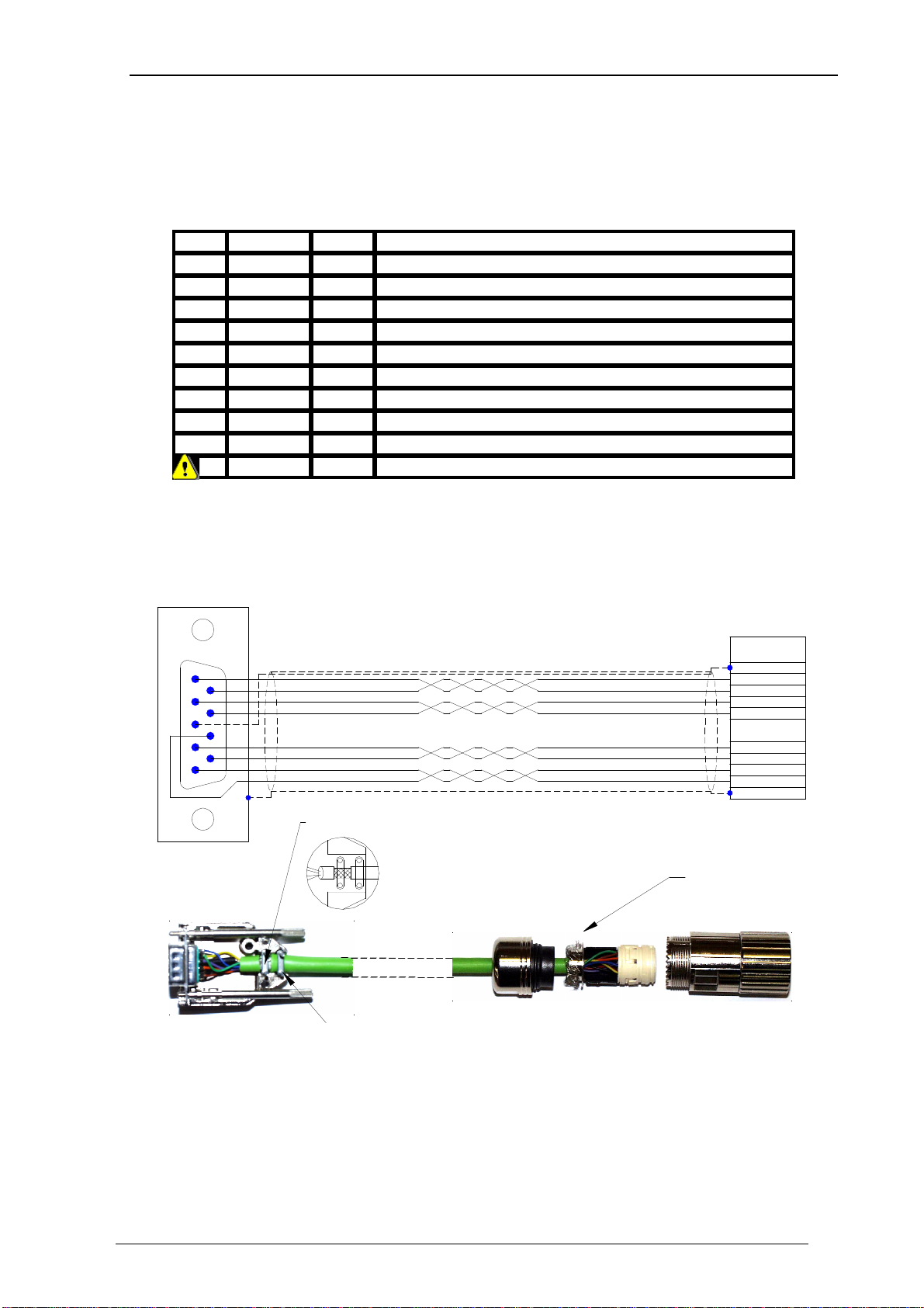
X11: Motor position feedback (resolver)
Connector: SUBD 9 way female
N° Name Type Description
1 S2 Inp
Sine Hi
2 S1 Inp
Cosine Hi
3 AGND
0V analogue
4 R1 Out
Reference Hi
5 °CM+ Inp
Motor temperature sensor Hi
6 S4 Inp
Sine Lo
7 S3 Inp
Cosine Lo
8 °CM- Inp
Motor temperature sensor Lo
9 R2 Out
Reference Lo
SHIELD Connect the shield to the shell of the connector
1
5
6
9
Resolver connector
SUB-D 9 way male
Metallic casing
Cable clamp
RESOLVER
SHIELD WIRE
2 TEMP -
SHIELD
5 REF +
6 TEMP +
9 REF -
4 SIN +
8 SIN -
7 COS -
3 COS +
CONNECTOR
Shield reverss
around the ring
connector M23
Resolver
4 twisted pairs (2 x 0.22mm)
Standard shield
DRIVE
SERAD
MOTOR
Shield clamp
Table of contents
Other SERAD DC Drive manuals


Popular DC Drive manuals by other brands


Danfoss
Danfoss VLT AutomationDrive FC 301 Design guide

Becker
Becker P5/20M operating instructions

i-MO
i-MO WD-L Installation and operating manual

Universal Lighting Technologies
Universal Lighting Technologies EVERLINE D700C120UVT-V Series manual

Vacon
Vacon 100 INDUSTRIAL Applications manual

Rowan Elettronica
Rowan Elettronica 380S instruction manual

Rockwell Automation
Rockwell Automation Reliance Electric SP200 user guide

Rockwell Automation
Rockwell Automation Allen-Bradley PowerFlex 750 Series Reference manual

Powtran
Powtran PI500 series manual

THORLABS
THORLABS MTS25-Z8 Original instructions

Lenze
Lenze 8400 protec Series Mounting instructions

Stober
Stober POSIDRIVE MDS 5000 Operation manual