Serai CR/41/24 Guide

E R A IS
GATE OPENER DIVISION
CR/41/24 I E
DAL 1965
CR/41/24 29.41/24 CONTROL UNIT FOR CONTROL OF 1 OR 2 24 Vdc MOTORS FOR THE
AUTOMATION FOR WING GATES
Page 1/12
INSTRUCTIONS FOR INSTALLATION
Thank you for having chosen SERAI ELETTRONICA, certain that you will obtain the performance necessary for use
from this product.
Remember that you are about to install a system classified as "motorised activation destined to move gates and
automatic doors in commercial and residential buildings, with access of vehicles and persons", which is considered
as potentially dangerous. Normally, it is your task and responsibility to make this system "safe" for how mush this is
reasonably possible.
Installation and maintenance of such a system must therefore by carried out exclusively by train, qualified and exert
staff, with "state-of-the-art" executions, as prescribed by law 37/08 and successive amendments and integrations.
The law prohibits the realisation of these types of plants by unqualified staff.
On realisation of its own products, SERAI has respected the following:
Reference Directives for CE marking:
machinery: 2006/42/EEC
low voltage: 73/23/EEC + 93/68/EEC
electromagnetic compatibility: 2004/108/EEC
General reference Standards:
electrical safety: IEC EN60335-1 + IEC EN60335-2-103
electromagnetic compatibility - emissions: IEC EN61000-6-3
electromagnetic compatibility - immunity: IEC EN61000-6-1
When installing the system, as well as that mentioned previously, please also respect.
General reference Standards:
safety of electrical plants in general environments: IEC 64-8 V2
Reference Standards specific of the product:
safety regarding use of motorised doors - requisites: UNI EN12453
safety regarding use of motorised doors - test methods: UNI EN12445
The SERAI products allow to realise systems that respond to these Standards. The following is very important
THE INSTALLER IS RESPONSIBLE FOR THE SYSTEM AND ITS FUNCTIONING IN COMPLIANCE WITH
STANDARDS
This manual must be read completely before proceeding with installation of the various parts of the plant.
!

INSTALLATION OF THE CR/41/24 CONTROL UNIT
Position the appliance in proximity of the gate in a way to reduce the length of the connection cable, to the rest of
the system, to a minimum.
For greater protection from atmospheric agents it is recommended to position the control unit under a roof or, even
better, in a room that has two lateral walls. It is also good practice to install the appliance at a height above 1.5 m,
where possible, in order to prevent it being tampered with by children.
WHERE TO POSITION THE CONTROL UNIT
The control unit leaves the factory with the lid positioned to open from the left side.
If you wish to open the lid from the opposite side, proceed as follows:
ATTENTION: This operation must be carried out
before fixing the container to the wall.
Insert a flat tip screwdriver into the fixing recess of the hinges
positioned on the rear of the base and lever on the attachment
notch of the hinge itself; pull the lid at the same time. (see
Fig.1)
Fig.1
Insert a flat tip screwdriver into the fixing recess of the hinge
positioned on the front part of the lid and lever on the notched
attachment of the hinge itself; pull the hinge at the same time.
(see Fig.2)
Fig.2
DAL 1965
Re-mount the hinges on the right side of the base by
inserting them in the relevant seats with the attachment
notch facing towards the inside of the container until the
attachment clicks (see Fig.3)
Fig.3
LID SET-UP FOR LID OPENING TO THE RIGHT
!
Page 2/12
CR/41/24 I E

DAL 1965
Page 3/12
CR/41/24 I E
BATTERY HOUSING AND CABLES INLET
Seats for fairleads PG11 and PG 13,5 which are easy to break through, are envisioned in the lower part of the
container for the passage of input cables
!ATTENTION: Close all inputs well to
prevent the entry of insects, which
may damage the control unit.
Two strips are supplied complete with screws for fixing the two 12V 2 Ah batteries (SERAI BT/15 or BT/20) onto the
lid of the container
!ATTENTION: Considering the weight
of the batteries, it is recommended
to install them at the end of
mounting, before closing the box.
OPENING AND CLOSING THE BOX
When opening the box, make sure that most of the hinges
escape from the guide on the bottom of the control unit in order
to guarantee that the lid remains open without obstructing the
control unit wiring operations.
In the closing phase, accompany the lid “especially in the
presence of the battery” until complete return of the hinges. Pay
attention that the gasket is inserted correctly. Close the lid using
the appropriate screws.
FIXING THE CONTROL UNIT TO THE WALL
It is recommended to position the appliance in proximity
of the gate in a way to reduce the length of the
connection cable, to the rest of the system, to a minimum.
The control unit must be fixed via the cable passage
holes facing downwards.
NO NO YES
Ø 6 ÷ 8 mm
Recommendations for connections in general rooms
1. Upstream from the system, prepare an omnipolar isolating switch with distance of 3 mm or more between the
contacts. As an alternative, use a 10Amagnet circuit breaker switch.
2. Make any type of connections always with the system not powered, i.e. with the isolating switch in the "open"
position ("0" symbol). In particular, the control unit must never be powered during wiring or while any expansion
cards are being inserted.
3. When installing the plant, use the following cables:
2
- for the power supplies to the motors: minimum 2.5 mm
2
- for the power supplies of the batteries and the electric locks: minimum 2.5 mm
22
- for the power supplies of the control unit: section 1.5mm for maximum length of 19m, section 2.5mm for lengths up
to 31m,
22
- for the flashing light section 0.75mm for maximum lengths of 3m, section 1.5mm for lengths up to 19m.
- for low voltage and current lines, such as photocells, control buttons, electro-mechanical key, sensitive edges and
22
other safety devices: section 0.5mm for maximum length of 50m, section 0.75mm for lengths up to 100m,
1 2 3 4 5 6 7 8 9 10 11 12 13 14 15 16 17 18 19 2021 22 2324
28 27
34 33
P3P2P1
-+
-+
-+
VELOC.
RALL
AMP
ON
1 2 43
SW1 ON
1 2 43
SW2
25 26
F2F2
F3F3
F1F1
F4F4
SW3

DAL 1965
WIRING DIAGRAM FOR 24Vdc MOTORS
EARTH
(BRAIDING)
ANTENNA
!
DISCONNECT THE POWER SUPPLY
-FROM THE NETWORK AND THE
BATTERY ID PRESENT, BEFORE
INTERVENING ON THE CONNECTIONS
!
2
ATTENTION: to connect the 24Vdc motors, use 2 cables with section of 2.5mm otherwise high voltage drops
will cause the force and speed of the motor to decrease, especially on the motor the furthest away
from the control unit, which could be slower than the other.
+
27 (+), 28 (-)
BUFFER POWER SUPPLY
for 2 12Vdc 2Ah batteries
SERAI BT/15 or BT/20
-battery charger included-
-
2 Batteries
12Vdc 2Ah
OPTIONAL
12
+
-
CLOSURE
PHOTOCELL
RECEIVERTRANSMITTER
OPENING
PHOTOCELL
RECEIVERTRANSMITTER
NC
NC
NA
NC
NA
PEDESTRIAN
START
STOP
NC
EDGE
+
-
24 Vdc
24Vdc OUTPUT
INTERMITTENT
FOR LIGHT
MAX 25W
24 Vdc
+
-
GATE INDICATOR LIGHT
OPEN O
ELECTRIC LOCK
(see SW2 dip2)
"AMP" POTENTIOMETER
regulation of the amperometric control
level. With the potentiometer at
maximum the amperometric control is
excluded”
"RALL" POTENTIOMETER
speed regulation during the slowing
phase, with the potentiometer at
maximum slowing is excluded
"VELOC." POTENTIOMETER
regulation of the velocity during normal
run
SW3 JUMPER
allows to have different sensitivity of the
amperometric control:
SW3 NOT INSERTED: normal
sensitivity
SW3 INSERTED: greater sensitivity
therefore the amperometric control
intervenes before
Page 4/12
CR/41/24 I E
1 2 3 4 5 6 7 8 9 10 11 12 13 14 15 16 17 18 19 20 21 22 23 24
28 27
34 33 P3
P2
P1
-+
-+
-+
VELOC.
RALL
AMP
ON
1 2 43
SW1 ON
1 2 43
SW2
25 26
F2F2
F3F3
F1F1
F4F4
SW3
LED
DL6
DL1
PED
DL2
START
DL3
STOP
DL4
FOTO
DL5
FOTO AP
DL7
COSTA
PAUSA LAVORO PROGR.
BATTERY
+-
FR1
F1 = T16A 250Vca - -
-BATTERY-
F2 = T16A 250Vca - -
-SECONDARY TRANSFORMER-
F3 = T2A 250Vca -delayed-
-CLAMPS 11-12, 13-14, 15-16-
F4 = F2A 250Vca -instant-
-PRIMARY TRANSFORMER-
FR1 = 0,5A -resettable fuses-
-CLAMPS 9-10-
delayed
delayed
M1 M2
NC
NC
NC
NC
K/71 E SR.24.71 E
K/71 I SR.24.71 I
230V~ ±10%
50/60Hz
F
N
BI-POLAR SWITCH FOR
THE UNLOCKING OF THE
MOTORS FROM INSIDE
OPTIONAL UNLOCKING
KEY FROM OUTSIDE

DAL 1965
Page 5/12
DEFINITION OF THE CLAMPS
CLAMPS CONNECTIONS DESCRIPTION
23 - 24
NETWORK
POWER SUPPLY
230Vac ±10% 50/60 Hz power supply input, which via fuse F4 powers the primary of the
toroidal transformer - already wired -
13 - 14
FLASHING
17 - 18
MOTOR M1
Motor M1 24Vdc power supply output for single wing or pedestrian wing (to which electric lock
can be connected), delayed closure.
9 - 10
PHOTOCELLS
POWER SUPPLY
Power supply output 24Vdc (9 = -, 10 = +) max 500mA for accessories such as photocells
6
OPENING
PHOTOCELL
5
CLOSURE
PHOTOCELL
1
4
PEDESTRIAN
CONTROL
STOP KEY
Stop control input (NC contact). When pressed it blocks functioning of the motors, if pressed
during the open gate pause time it annuls automatic closure.
2
START
COMMAND
Start control input (NO contact), controls the opening and closure in step-by-step mode.
N.B. This function can be modified as described in "modify controls".
Photocell input active in opening and closing (NC contact).
If blacked-out in the opening phase, the gate stops, re-starts opening as soon as the photocell
is no longer engaged.
If blacked-out in the closure phase, the gate stops, re-opens as soon as the photocell is no
longer engaged.
Photocell input active only in closing (NC contact). If blacked-out in the closure phase, the
gate stops and then re-opens.
COMMON
INPUTS
Inputs common clamps
11 - 12
CONTROL FOR
ELECTRIC LOCK
OR GATE OPEN
INDICATOR LIGHT
33 - 34
RECEIVER
ANTENNA
INCORPORATED
Flashing light power supply output (24Vdc-max 25W) to be used with flashing light without -
SERAI RZ/24F- internal electronics. Flashing is fast during closure, slow during opening and
very slow when functioning with battery.
8
3 - 7
24Vdc output (11 = -, 12 = +) with the following functioning:
With SW2dip2 OFF: impulse control for electric lock -SERAI M/83/1-.
With SW2dip2 ON: control with the gate open indicator light function
Input for the connection of the antenna for the built-in receiver.
(33=BRAIDING/EARTH, 34=ANTENNA)
Sensitive edge input (NC contact), inverts movement by 10cm.
SENSITIVE
EDGE
LEDS INDICATION
LED
DL5=PH OP
DL4=PHOTO
DL3=STOP
DL1=PED
DL2=START
ON OFF
FUNCTION
Internal photocell
External photocell
Stop button
PEDESTRIAN button
Open/Close button
Opening photocell free from
obstacles
Closure photocell free from
obstacles
Stop button in normal state
Pedestrian button pressed
Open/Close button pressed
Opening Photocell blocked out
(presence of an obstacle)
Closure Photocell blocked out
(presence of an obstacle)
Stop button pressed
Pedestrian button in normal state
Open/close button in normal state
DL6 Programming Indicates the various phases of the programming
DL7=COSTA Sensitive edge Sensitive edge in normal state Sensitive edge pressed
ATTENTION: this voltage is not present in battery functioning with
gate at a standstill.
15 - 16
AUXILIARY
POWER SUPPLY
Power supply output 24Vdc (15 = +, 16 = -) max 200mA for accessories that must always be
powered, for example external radio receivers.
19 - 20
MOTOR M2
M2 motor 24Vdc power supply output for delayed wing opening
21 - 22
TRANSFORMER
SECONDARY
INPUT
20Vac input for power supply of the circuit board supplied via a toroidal transformer- already
wired-
27 - 28
OPTIONAL
BATTERIES
Input for the connection of N°2 12V 2Ah buffer batteries (optionals, e.g. SERAI BT/15 or
BT/20) to guarantee functioning of the automation in the case of a power cut. In presence of
the circuit board network voltage, it recharges the batteries via the built-in battery-charger
CR/41/24 I E
Pedestrian control input (NO contact). With DIP1 SW1 OFF only the wing connected to M1
opens. With DIP1 SW1 ON the single wing opens (M1) for 7s.
N.B. This function can be modified as described in "modify controls".

DAL 1965
SETTING OF EACH INDIVIDUAL MICRO SWITCH
DESCRIPTION OF THE FUNCTIONING
FUNCTIONING
Single wing logic: just the output indicated with M1 is controlled
Double wing logic: outputs M1 and M2 are controlled (M2 wing
opening delay)
GATE CONFIGURATION
1 2 3
ON
4 1 2 3
ON
4
1 2 3
ON
4 1 2 3
ON
4
ENABLES/DISABLES
IMMEDIATE CLOSURE
FUNCTIONING WITH
PASSAGE ON
CLOSURE PHOTOCELL
1 2 3
ON
4 1 2 3
ON
4
1 2 3
ON
4 1 2 3
ON
4
Immediate closure function enabled: the engagement and
disengagement of the closure photocell makes the gate re-close (when
the gate is open) automatically after 5s.
Immediate closure function disabled
Hammering activated: the electric lock is activated during a brief
closure phase against the stops and is deactivated after the start-up of
M1.
Hammering deactivated: The electric lock is activated just after the
start-up of M1 and is deactivated a little after the start-up of M1.
1 2 3
ON
4 1 2 3
ON
4
1 2 3
ON
4 1 2 3
ON
4
1 2 3
ON
4 1 2 3
ON
4
1 2 3
ON
4 1 2 3
ON
4
ELECTRIC LOCK
HAMMERING
1 2 3
ON
4 1 2 3
ON
4
1 2 3
ON
4 1 2 3
ON
4
PEAK ON START-UP
Peak on start-up activated: on start-up, the motors are powered at
maximum voltage for 2s.
RECOMMENDED ESPECIALLYIN THE WINTER PERIODS
Peak on start-up deactivated: on start-up, the motors are powered at
the voltage set with the potentiometer.
ATTENTION: in this case, there may be difficulties on
start-up if the force is regulated low
1 2 3
ON
4 1 2 3
ON
4
1 2 3
ON
4 1 2 3
ON
4
CLAMPS 11-12
FUNCTIONING MODE
Open gate indicator light output: flashing during gate movement, on
with gate open and off with gate closed
!
ATTENTION:
The micro switches must be regulated when the control unit is not powered. The regulations made
to the micro switches become active on switch-on.
We recommend, after having adjusted the micro switches, to program the work times (see control
unit programming).
!
MICRO SWITCHES
SETTING
SW 2SW 1
1 2 3
ON
4 1 2 3
ON
4
1 2 3
ON
4 1 2 3
ON
4
DO NOT USE
DO NOT USE
Leave in OFF
ENABLES/DISABLES
STEP-BY-STEP
FUNCTIONING
Step-by-step function disabled
During opening: the sending of a START control is ignored, the gate
continues to open
During closure: the sending of a START control blocks the gate for a
few seconds and then it re-opens
During the gate open pause: a START control annuls the pause time
and makes the gate close immediately
Step-by-step function enabled
During opening: sending a START control causes the movement to
stop, a successive one causes the gate to close
During closure: sending a START control causes the movement to
stop, a successive one causes the gate to open
During the gate open pause: a START control annuls the pause time
and makes the gate close immediately
Electric lock output: impulse control for electric lock whose
functioning depends on the position of SW1dip3
Leave in OFF
Page 6/12
CR/41/24 I E

DAL 1965
Page 7/12
PROGRAMMING THE CONTROL UNIT
The programming must be carried out point by point. In the case of errors during this phase, it is necessary to
proceed with new programming, which will delete the first.
Before programming, the system must be complete with all electrical devices and safety devices connected
(buttons, photocells, flashing lights etc.).
Check their correct functioning:
All signal LEDs of the NC inputs (stop, photocells, etc) are on.
All signal LEDs of the NO inputs (start, pedestrian) are off.
In the case of anomalies check and remove the cause.
ATTENTION: The normally closed (NC) inputs that are not used must be jumpered.
Regulate the "AMP", "RALL", "VELOC." potentiometers according to requirements.
With the control unit powered, press and hold down button P3 (PROGR) until the motors start the closure
action (about 10s). If the gate is already closed, the board makes this search anyway, forcing on the stops for a
few seconds. The DL6 LED starts to flash to indicate that the control unit is in the programming state.
After the gate is closed, the M1 motor wing is opened and after about 3 s, the wing connected to M2 is also
opened.
When the wings reach the stops, the motors shutdown automatically. In this way, the run is calculated and the
slowing points are defined (about 4s before the mechanical stops) which are the same in opening and closure
modes.
Successively, the gate automatically closes with phase difference between the wings of about 3 seconds and
performs slowing before stopping against the stops.
The control unit automatically leaves the programming phase, switching the DL6 LED off and is ready for
normal functioning
ATTENTION: - If any potentiometer is varied, the programming must be repeated.
The functioning time of the motors is controlled by two independent digital timers. If any control interrupts the run of
the wing before the end, the timer stops and the time passed is memorised. The appliance is therefore able to
establish the partial work time necessary to terminate the wing run, with a certain approximation, always slowing in
the programmed point.
ATTENTION: The lack of power supply to the circuit board (network or battery) causes the loss of the memorised
position. Successively to commissioning, a start control is for opening without activation of the
amperometric control, therefore the gate re-aligns on the opening stops.
AUTOMATIC PROGRAMMING FOR GATE WITH TWO WINGS (DIP1 SW1 OFF)
Automatically sets work times, slowing point and phase differences of the wing when opening and closing
Regulate the "AMP", "RALL", "VELOC." potentiometers according to requirements.
With the control unit powered, press and hold down button P3 (PROGR) until the motor starts the closure
action (about 10s). If the gate is already closed, the board makes this search anyway, forcing on the stop for a
few seconds. The DL6 LED starts to flash to indicate that the control unit is in the programming state.
After the gate is closed, the wing of motor M1 is opened and on arrival against the stop, the motor shuts down
automatically. The run is calculated and the slowing points are defined in this way (about 4s before the
mechanical stroke) which are the same in opening and closure modes.
Successively, the gate closes automatically, slowing before stopping against the stop.
The control unit automatically leaves the programming phase, switching the DL6 LED off and is ready for
normal functioning
AUTOMATIC PROGRAMMING FOR GATE WITH SINGLE WING (DIP1 SW1 ON)
Automatically sets work times and wing slowing point
CR/41/24 I E
CONTROLS MODIFICATION
It is possible to modify the functioning of the 1 and 2 inputs in this way:
- Input 2 functions as "START": with control unit off, press and hold keys P3 (PROGR) and P2 (WORK)
simultaneously and apply power supply.
- Input 2 functions as "CLOSE only": with control unit off, press and hold keys P3 (PROGR) and P1 (PAUSE)
simultaneously and apply power supply.
- Input 1 functions as "PEDESTRIAN": with control unit off, press and hold keys P2 (WORK) and P1 (PAUSE)
simultaneously and apply power supply.
- Input 1 functions as "OPEN only": with control unit off, press and hold keys P1 (Pause) and P2 (WORK) and P3
(PROGR) simultaneously and apply power supply.

Regulate the "AMP", "RALL", "VELOC." potentiometers according to requirements.
With the control unit powered and gate closed, press and release button P3 (PROGR), the DL6 LED starts to
flash to indicate that the control unit is found in the programming state.
Press and release key P2 (WORK), the wing connected to M1 starts to open.
When Motor M1 should start slowing (we recommend at least 50cm before the stop) press key P2 (WORK). The
motor M1 slows down.
ATTENTION: skip this point if slowing has been excluded ("RALL" potentiometer at maximum)
When the motor M1 reaches the opening stop, the motor shuts down automatically (motor shutdown control
intervention)
Press and release key P2 (WORK), the DL6 LED starts to flash quickly to indicate the start of the time difference
count when opening
When the desired phasing time has passed in opening (max 15s), press the P2(WORK) key and the motor M2
starts in opening mode and the DL6 LED starts to flash normally
ATTENTION: if you want a nil phase difference in opening, hold key P2 (WORK) down until M2 starts
When Motor M2 should start flowing (we recommend at least 50cm before the stop) press key P2 (WORK). The
motor M2 slows down.
ATTENTION: skip this point if slowing has been excluded ("RALL" potentiometer at maximum)
When the motor M2 reaches the opening stop, the motor shuts down automatically (motor shutdown control
intervention)
Press and release key P2 (WORK), the motor M2 starts to close
When Motor M2 should start flowing (we recommend at least 50cm before the stop) press key P2 (WORK). The
motor M2 slows down.
ATTENTION: skip this point if slowing has been excluded ("RALL" potentiometer at maximum)
When the motor M2 reaches the closing stop, the motor shuts down automatically (motor shutdown control
intervention)
Press and release key P2 (WORK), the DL6 LED starts to flash quickly to indicate the start of the time difference
count when closing
When the desired phasing time has passed in closing mode (max 15s), press the P2(WORK) key and the motor
M1 starts in closure mode and the DL6 LED starts to flash normally
ATTENTION: if you want a nil phase difference in closure, hold key P2 (WORK) down until M1 starts
When Motor M1 should start slowing (we recommend at least 50cm before the stop) press key P2 (WORK). The
motor M1 slows down.
ATTENTION: skip this point if slowing has been excluded ("RALL" potentiometer at maximum)
When the motor M1 reaches the closing stop, the motor shuts down automatically (motor shutdown control
intervention)
The control unit automatically leaves the programming phase, switching the DL6 LED off and is ready for normal
functioning
MANUAL PROGRAMMING FOR GATE WITH TWO WINGS (DIP1 SW1 OFF)
The installer sets work times, slowing point and phase difference time according to requirements
Regulate the "AMP", "RALL", "VELOC." potentiometers according to requirements.
With the control unit powered and gate closed, press and release button P3 (PROGR), the DL6 LED starts to
flash to indicate that the control unit is found in the programming state.
Press and release key P2 (WORK), the wing connected to M1 starts to open.
When Motor M1 should start slowing (we recommend at least 50cm before the stop) press key P2 (WORK). The
motor M1 slows down.
ATTENTION: skip this point if slowing has been excluded ("RALL" potentiometer at maximum)
When the motor M1 reaches the opening stop, the motor shuts down automatically (motor shutdown control
intervention)
Press and release key P2 (WORK), the motor M1 starts to close
When Motor M1 should start slowing (we recommend at least 50cm before the stop) press key P2 (WORK). The
motor M1 slows down.
ATTENTION: skip this point if slowing has been excluded ("RALL" potentiometer at maximum)
When the motor M1 reaches the closing stop, the motor shuts down automatically (motor shutdown control
intervention)
The control unit automatically leaves the programming phase, switching the DL6 LED off and is ready for normal
functioning
MANUAL PROGRAMMING FOR GATE WITH SINGLE WING (DIP1 SW1 ON)
The installer sets work times and slowing point according to requirements
DAL 1965
Page 8/12
CR/41/24 I E
MANUAL PROGRAMMING VIA REMOTE CONTROL
When a remote control has been programmed, it is possible to perform manual programming of the remote
control key replacing button P2 (WORK) of the control unit
To do this, follow the same procedures mentioned above, only instead of entering programming by pressing button
P3 (PROGR), press P3 (PROGR) + P2 (WORK) at the same time.

DAL 1965
Page 9/12
PROGRAMMING OPEN GATE PAUSE TIME (AUTOMATIC RE-CLOSURE)
With the control unit powered and gate closed, press key P3 (PROGR.) once. The LD6 LED starts to flash
indicating that the board has entered the programming phase.
Press key P1 once (PAUSE), the control unit starts the open gate pause count, highlighted with fast
flashing of the DL6 LED and of the flashing light.
When the desired time has passed, press key P1 (PAUSE) again, the control unit automatically memorises
the time passed between the two times the key P1 (PAUSE) was pressed and leaves programming, going
back to normal functioning.
If key P1 (PAUSE) is not pressed a second time, after 120s the control unit escapes from the programming
memorising the max time of 120s.
ACTIVATE AUTOMATIC RE-CLOSURE (maximum time that can be set 120s)
Press and hold key P1 (PAUSE) until LED DL6 switches off.
The control unit leaves the programming phase and sets itself for normal functioning.
Automatic re-closure is deactivated in this way.
DEACTIVATE AUTOMATIC RE-CLOSURE
With the control unit powered and the gate closes, press key P3 (PROGR.) once to enter programming.
LED DL6 starts to flash, indicating that the board has entered the programming phase.
BEHAVIOUR WHEN
STRIKING AN
OBSTACLE
FOLLOWING THE
INTERVENTION OF
THE AMPEROMETRIC
CONTROL
during closing at
normal speed
during opening/closing at
slowed speed
during opening at
normal speed
The gate blocks, i.e. the obstacle is interpreted as the
stop
AMPEROMETRIC SAFETY CONTROL
The control unit has a current absorption control able to intervene in the case of a blow with an obstacle during
movement at normal speed. The current level, above which the amperometric control intervenes, is set by
regulating the "AMP" potentiometer. The intervention of the amperometric control can be more or less rapid
depending on the sensitivity set with the SW3 jumper.
The gate inverts movement for about 5cm. It re-closes
(part M2 and after the phasing time in closure mode M1
starts) after the open gate pause time (if automatic re-
closure is activated) or after 30s (if automatic re-closure
is deactivated).
!
MOTOR SHUTDOWN CONTROL
The control unit has "shutdown motor" control able to intervene with the same consequences as the amperometeric
control, when the motor remains completely at a standstill for a couple of seconds.
It is a control that cannot be regulated or excluded - it also intervenes with amperometric control excluded - which is
used to identify the stops during slowing and any gate blocks during the normal run.
ATTENTION:
- Setting an amperometric level that is too low varies external factors - e.g. gusts of wind, the
increase of friction between day and night etc.- can be interpreted as a blow with an obstacle
with intervention of the amperometric control. For this reason it is possible to exclude the
amperometric control - with "AMP" potentiometer at maximum- even if the motor shutdown
control remains.
- If the amperometric control is excluded the safety of the blow is less -the gate continues to push
with maximum force- and therefore it is the responsibility of the installer to use all other
safety systems -for example, edges- according to that established by the Standards in
force.
CR/41/24 I E
The gate inverts movement for about 5cm and then re-
opens (first M1 and after the phase difference time in
opening M2 starts) up to the opening stops. It closes
again after the gate open pause time (if automatic re-
closure is active) or after 30 s (if automatic closure is
deactivated).
N.B. After 2 consecutive blows in closure, the gate
blocks and remains in stand-by for a closure
control

DAL 1965
LEARNING THE RADIO CONTROL CODE
The circuit board incorporates a dual-channel radio receiver at 433.92 MHz, which allows to control the gate at a
distance via micro switch remote controls from the OG/02, OG/04 range and self-learning remote controls from the
OG/62, OG/64, OG/28, OG/48, OG/52, OG/54, OG/82/1 and OG/84 range. Both of the channels are used exclusively to
control the gate. In particular channel 1 of the radio receiver acts from start, while channel 2 acts from the pedestrian.
DELETING CODES IN THE MEMORY
The deleting of all radio codes memorised is carried out by pressing and holding the P3 (PROGR.) and P1
(PAUSE) keys at the same time until the DL6 LED switches off (about 10s) without sending any radio code.
!ATTENTION: - before using a remote control, perform the programming procedure.
- the maximum number of codes that can be memorised is equal to 32 as start
control + 32 for pedestrian control (other combinations are not possible e.g. 40
start + 24 pedestrian etc.) . Below two examples of codes that can be memorised:
- example A: 32 self-learning remote controls OG/62, OG/64, OG/28, OG/48, OG/52,
OG/54, OG/82/1 and OG/84 as start control (e.g. left button) + 32 self-
learning remote controls OG/62, OG/64, OG/28, OG/48, OG/52, OG/54,
OG/82/1 and OG/84 as pedestrian control (e.g. right button)
- example B: 31 self-learning remote controls OG/62, OG/64, OG/28, OG/48, OG/52,
OG/54, OG/82/1 and OG/84 as start control (e.g. the left button) + 1 micro
switches remote control OG/02, OG/04 as start control (the others do
not have to be memorised OG/02 and OG/04 just set the micro switches in
the same sequence as that memorised) + 31 self-learning remote
controls OG/62, OG/64, OG/28, OG/48, OG/52, OG/54, OG/82/1 and
OG/84 as pedestrian control (e.g. the right button) + 1 micro switches
remote control OG/02, OG/04 as pedestrian control (the others do not
have to be memorised OG/02 and OG/04 just set the micro switches in the
same sequence as that memorised)
!
LEARNING START CODE
- With the control unit powered and the gate closes, press key P3 once (PROGR.) to enter programming. The DL6
LED starts to flash to indicate that the control unit is in the programming state.
- Press the remote control button (e.g. on the left), which wants to act as start control and hold it down until the DL6
LED switches off. The control unit has memorised the radio code received and automatically leaves programming,
setting itself for normal functioning.
- Repeat the procedure if several remote controls must be memorised.
LEARNING PEDESTRIAN CODE
- With the control unit powered and the gate closes, press key P3 twice (PROGR.) to enter programming. The DL6
LED starts to flash quickly to indicate that the control unit is in the programming state.
- Press the remote control button (e.g. on the right), which wants to act as pedestrian control and hold it down until
the DL6 LED switches off. The control unit has memorised the radio code received and automatically leaves
programming, setting itself for normal functioning.
- Repeat the procedure if several remote controls must be memorised.
12 34 56 78910
123 45 67 8 910
!
MODIFY THE FACTORY
CONFIGURATION TO PREVENT
UNDESIRED CONTROLS
CONFIGURATION OF MICRO SWITCHES ONLY IN THE CASE OF OG/02 AND OG/04 REMOTE CONTROLS
Only if OG/02 and OG/04 remote controls with micro switches are used, before performing learning of the codes on
the receiver, the factory configuration of the micro switches must be modified to prevent undesired controls
ATTENTION: before starting first programming or deleting the remote controls, temporarily
disconnect the antenna to prevent the receiver from acquiring other signals during this phase,
which may cause incorrect functioning of the automation. Re-connect the antenna when the
procedure has ended.
Page 10/12
CR/41/24 I E

TECHNICAL DATA OF THE CR/41/24 CONTROL UNIT
EXPANSION OF THE MINITRANSMITTER NUMBER
If the 32 remote controls that can be memorised in the built-in receiver are not sufficient, it is possible to increase them
by inserting the SOG/4A receiver (that takes the number of remote controls to 40) eventually with the addition of the
SOG/2A expansion (that takes the number of remote controls to 794).
After having inserted the SOG/4A receiver, all codes memorised in the built-in receiver must be deleted and all
of the remote controls must be re-programmed on the new SOG/4A receiver, see specific instructions. The
antenna must be moved from the clamp on the control unit - 33/34 - to the clamp found on the SOG/4A.
2ND CHANNEL
OUTPUT
CONTROL
AUXILIARY
ANTENNA
NC
C
NA
Channel 2 output (relay contact)
Max voltage applicable= 24Vac/dc
Max current applicable= 1A
Install additional relay relevantly
dimensioned for the specific case.
ELECTRIC LOCK
LIGHTS
OTHER AUTOMATIONS
OTHER
INSERT THE
SOG/4A
RECEIVER
1ST CHANNEL OUTPUT
START COMMAND
OF THE CONTROL UNIT
PEDESTRIAN CONTROL
ON CR/41/24 -CLAMPS 1-3-
DISCONNECT THE POWER
SUPPLY BEFORE INTERVENING
ON THE CONNECTIONS
1 2 3 4 5 6 7 8 9 10 11 12 13 14 1516 17 18 19 20 21 22 23 24
28 27
34 33 P3
P2
P1
-+
-+
-+
VELOC.
RALL
AMP
ON
1 2 43
SW1 ON
1 2 43
SW2
25 26
F2F2
F3F3
F1F1
F4F4
SW3
LED
DL6
DL1
PED
DL2
START
DL3
STOP
DL4
FOTO
DL5
FOTO AP
DL7
COSTA
PAUSA LAVORO PROGR.
BATTERY
+-
Power supply transformer: 230/20 Vac, 130VA
Internal battery charger capacity 28Vdc, 0.5A
Optional battery capacity: 2x12Vdc 2Ah
Motors power supply: 24Vdc 4A
Accessories power supply: 24Vdc 500mA
Flashing light power supply: 24Vdc, max 25W
Electric lock power supply: 24Vdc
Pause time adjustment: from 1 to 120s
Regulation delay in opening/closure: from 0 to 15s
Amperometric control regulation: "AMP" potentiometer
Slowing speed regulation: "RALL" potentiometer
Normal speed regulation: "VELOC" potentiometer
Operating temperature: -20°C ÷ +60°C
Dimensions (H x L x D) and weight: 270x212x118mm, 2.5Kg
DAL 1965
Page 11/12
CR/41/24 I E
BATTERY FUNCTIONING
If there is a power cut, the system continues to function with the batteries, if they are connected. In this case, to
save energy, the only differences are:
- flashing is very slow
- the photocells output -clamps 9-10- is removed with gate at standstill, therefore they reactivated on the open control
- the start control is taken while the batteries are charged. When the battery is not charge the control unit remains
powered until the batteries are flat but do not take the start control.
When the mains voltage returns, the built-in battery charger charges and maintains the batteries in this state.
Twenty-four hours are required for complete re-charging.

TROUBLESHOOTING
PROBLEM CAUSE SOLUTION
The motor reducer
does not work
No voltage to
the motors
Check the presence of voltage at the input clamps
power supply to the motor
Check that the power supply cable is not interrupted.
(the power supply cable must be replaced
by an authorised technician)
Check the fuses on the control unit
Incorrect regulation
of the slowing point
Repeat the programming of work times, paying attention to set
slowing at no less than 50÷70cm from the stop.
No voltage to the
control unit
Check the network fuse and the presence of network voltage
Check the network voltage -if present-
Meeting the stops
makes movement
reverse
Slowing speed set with
"SLOW" potentiometer
too low
INCREASE THE "RALL" POTENTIOMETER: the "RALL"
potentiometer, as well as the speed also decreases the power to
the motor. For this reason a regulation that is too low can cause
the gate to stop before reaching the mechanical stops. This stop
also depends on the external environmental features, which vary
greatly between summer and winter and between the first hours
of the day with respect to the central hours. For this reason the
gate may stop occasionally.
Repeat work times programming by setting a quicker speed with
the "RALL” potentiometer.
The gate
occasionally does
not complete the
entire slowing
period, but blocks
before
Intervention of the
amperometeric
control
During movement
and normal speed
the gate inverts
movement
The motor moves
with difficulty
Insufficient motors
power supply
THE POWER SUPPLY CABLES TO THE MOTORS MUST
HAVE ADEQUATE SECTION: we recommend cables measuring
2
2.5mm for 24vdc motors. cables with smaller section cause
large voltage drops that make the motor speed force decrease,
especially on the motor furthest away from the control unit
INCREASE THE "AMP" POTENTIOMETER: the "AMP"
potentiometer regulates the amperometeric control intervention,
which intervenes every time that the gate stops moving for a brief
period of time due to external factors-such as gusts of wind for
example-. Therefore, in the case of particularly windy areas, it is
recommended to exclude the amperometric control by taking the
potentiometer to MAX
INCREASE THE "VELOC" POTENTIOMETER: the "VELOC"
potentiometer regulates the speed of the motors, decreasing the
voltage. check the correct functioning by taking the
potentiometer to MAX
CR/41/24 I E 03 12 110321 A4Vf/r -IS CR41-24-E
Intervention of the
amperometric control
INCREASE THE "AMP" POTENTIOMETER: the "AMP"
potentiometer regulates the amperometeric control intervention,
which intervenes every time that the gate stops moving for a brief
period of time due to external factors-such as gusts of wind for
example-. therefore, in the case of particularly windy areas, it is
recommended to exclude the amperometric control by taking the
potentiometer to MAX
ELETTRONICA PADOVA
I
SINCE 1965
MADE IN ITALY
VIA ENRICO FERMI, 22
35020 LEGNARO - PADOVA
I T A L I A
PHONE +39 049 79 08 58
FAX +39 049 88 30 529
E-MAIL [email protected]
WEB www.serai.com
TERMS OF GUARANTEE
The company reserves the right to make modifications to the equipment without prior notice thereof. SERAI products are covered by a standard guarantee with a term of 24 months.
Coverage starts on the date on which the tax document constituting proof of purchase is issued and guarantee services shall be provided on the company's premises at Legnaro - PD -
or at the Authorised Service Centres. Carriage costs shall be borne by the Customer.
CE CONFORMITY DECLARATION
SERAI spa declares that the product CR/41/24 has been desifned and manufactured according to the above mentioned directives and standards
WEEE DIRECTIVE 2002/96/EC
This appliance was manufactured after 13/08/2005. To protect the environment: when the equipment is no longer needed, take it to a special WEEE (Waste Electric and
Electronic Equipment) collection centre. Do not dispose of it with normal household waste.
Table of contents
Popular Control Unit manuals by other brands
ETC
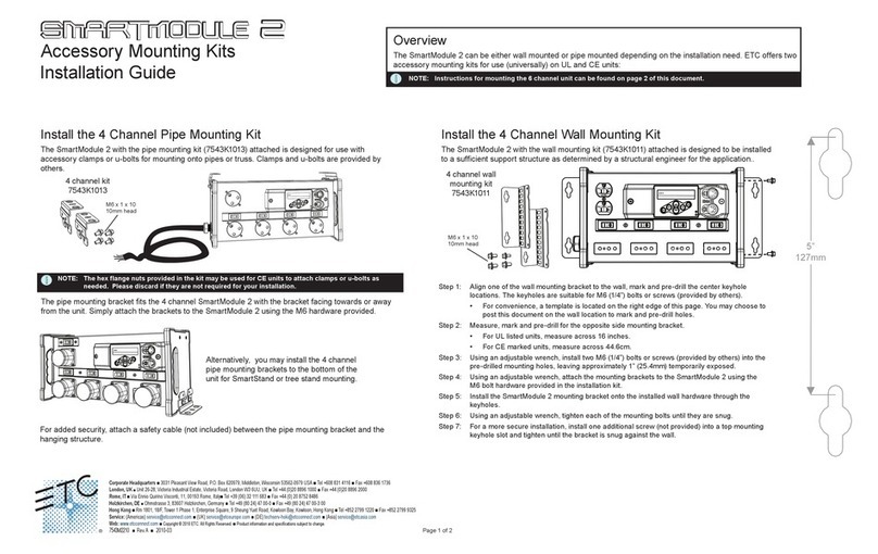
ETC SmartModule 2 installation guide
National Instruments
National Instruments PXIe-6591R user manual
PEHA
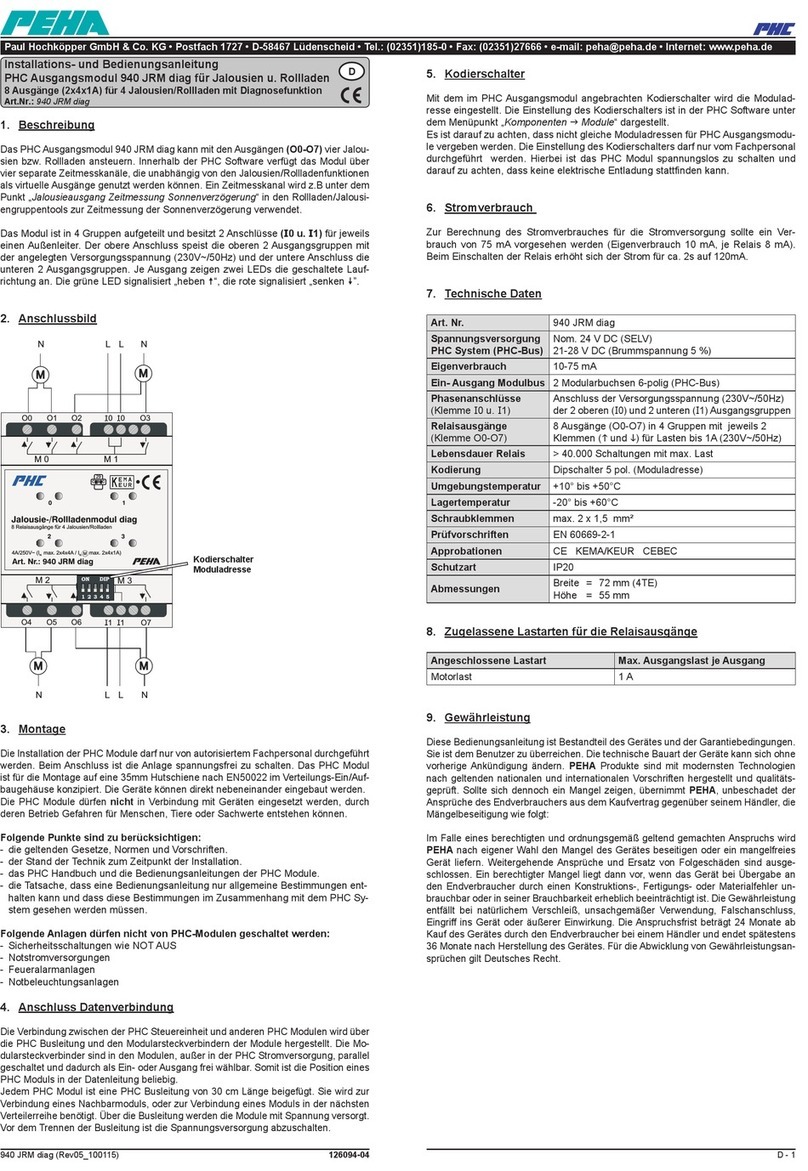
PEHA PHC 940 JRM diag Installation and operating instructions
Keysight
Keysight M8192A user guide
Nice
Nice MC424L Instructions and warnings for installation and use
Agilent Technologies
Agilent Technologies G1323B user guide

Pickering
Pickering 40-574 user manual
American Standard
American Standard SELECTRONIC 6067.111 installation instructions
iseg
iseg NHS Series Technical documentation
Rockwell Automation
Rockwell Automation AB quality Allen-Bradley 1746-INT4 user manual
National Instruments
National Instruments 6587 Getting started guide

GatesAir
GatesAir PT-353 Installation and operation manual
