GatesAir PT-353 User manual

GatesAir.com
Intraplex®
PT/PR-353 32/44.1/48 ksps
Stereo Linear Program Audio Module
PT-353 Program Audio Transmit Module
PR-353 Program Audio Receive Module
Version 1.1
Installation and Operation Manual


Publication Information
©2014 GatesAir, Inc. . Proprietary and Confidential.
GatesAir considers this document and its contents to be proprietary and confidential. Except for making a
reasonable number of copies for your own internal use, you may not reproduce this publication, or any part
thereof, in any form, by any method, for any purpose, or in any language other than English without the written
consent of GatesAir. All others uses are illegal.
This publication is designed to assist in the use of the product as it exists on the date of publication of this manual,
and may not reflect the product at the current time or an unknown time in the future. This publication does not in
any way warrant description accuracy or guarantee the use for the product to which it refers.
GatesAir reserves the right, without notice to make such changes in equipment, design, specifications,
components, or documentation as progress may warrant to improve the performance of the product.
GatesAir reserves the right, without notice to make such changes in equipment, design, specifications,
components, or documentation as progress may warrant to improve the performance of the product.
Trademarks
AudioLink PLUS™, HD Link™, IntraGuide®, Intraplex®, NetXpress™, NetXpress LX™, STL PLUS®, SynchroCast®, and
SynchroCast3™ are trademarks of GatesAir Corporation. Other trademarks are the property of their respective
owners.
Customer Service Contact Information
www.gatesair.com
GatesAir
3200 Wismann Lane
Quincy, Il 62305 USA
For Technical Support including Service, Training, Repair and Service Parts:
www.gatesair.com/services/technical-support.aspx
Americas:
24/7 Technical Support +1 217 222 8200
Email tsup[email protected]
Europe, Middle East and Africa:
24/7 Technical Support +1 217 222 8200
Email [email protected]
Asia:
24/7 Technical Support +1 217 222 8200
Email [email protected]

Version Date Revisions Made Section Pages Editor
1.1 2/17/10 Put entire manual into new template and reformatted.
Added information on MA-558 and MA-559. All
2.5, 2.11
6
A
All
2-2, 2-4
6-2
A-2 – A-3
LD
*Version numbers usually correspond to software releases. If the manual versions differ in number from the release, the front page shows both
the manual version and the release version.

No header here
GatesAir i
Intraplex Products
Table of Contents
Section 1 – Introduction................................................................ 1-1
Section 2 – Functional Description ................................................ 2-1
2.1 Configurations................................................................................2-1
2.2 Interoperability...............................................................................2-1
2.3 PT-353 Transmitter .........................................................................2-1
2.4 PR-353 Receiver ............................................................................. 2-2
2.5 Alerts and Alarms ...........................................................................2-2
2.6 Rate Adaptation..............................................................................2-3
2.7 Reed-Solomon Forward Error Correction.............................................2-3
2.8 External Timing ..............................................................................2-3
2.9 Channel Status...............................................................................2-4
2.9.1 Transport ........................................................................................... 2-4
2.9.2 Overwriting......................................................................................... 2-4
2.10 Web Browser Interface ....................................................................2-4
2.11 Input/Output Connections................................................................2-4
Section 3 – Installation & Operation.............................................. 3-1
3.1 Inspection......................................................................................3-1
3.2 Installation ....................................................................................3-1
3.3 PT/PR-353 Switch Configuration........................................................3-2
3.3.1 Card Address Setting Switches (PT-353 SW4 and PR-353 SW5).................. 3-4
3.3.2 Configuration Switch Banks (PT-353 SW6 and PR-353 SW2)...................... 3-5
3.3.2.1 Two Channel Operation (Position 1 – PT-353 SW6 and PR-353 SW2)............... 3-7
3.3.2.2 Sampling Rate (Positions 2, 3, and 4 – PT-353 SW6 and PR-353 SW2)............ 3-7
3.3.2.3 Test Tone Generator (Position 5 – PT-353 SW6 and PR-353 SW2)................... 3-7
3.3.2.4 Pre-Emphasis/De-Emphasis (Position 6 – PT-353 SW6 and PR-353 SW2)......... 3-8
3.3.2.5 DC Offset Removal (Position 7 – PT-353 SW6)............................................. 3-8
3.3.2.6 CAS (Position 8 – PT-353 SW6 and PR-353 SW2) ......................................... 3-8
3.3.2.7 SPARE (Position 9 – PT-353 SW6).............................................................. 3-8
3.3.2.8 FEC – Forward Error Correction (Position 9 – PR-353 SW2)............................ 3-8
3.3.2.9 ASRC (Position 10 – PT-353 SW6).............................................................. 3-8
3.3.2.10 SPARE (Positions 5, 7, and 10 – PR-353 SW2) ............................................. 3-8
3.3.3 Time Slot Selection Switches................................................................. 3-9
3.3.3.1 SPARE (Positions 1-3 – PT-353 SW2 and PR-353 SW3) ................................. 3-9
3.3.3.2 Starting Time Slot (Positions 4-8 – PT-353 SW2 and PR-353 SW3) ................. 3-9
3.3.4 Service/Control Switch Banks.............................................................. 3-11
3.3.4.1 TERM (Position 1 – PT-353 SW3 and PR-353 SW4) ..................................... 3-11
3.3.4.2 AUX (Position 2 – PT-353 SW3 and PR-353 SW4) ....................................... 3-11
3.3.4.3 REMOTE (Position 6 – PT-353 SW3 and PR-353 SW4) ................................. 3-11
3.3.4.4 OFF (Position 4 – PT-353 SW3 and PR-353 SW4) ....................................... 3-11
3.3.5 Programmable Gain Settings (GAIN) .................................................... 3-12

PT/PR-353 Audio Module Installation & Operation Manual Table of Contents
Version 1.1
ii GatesAir
Intraplex Products
3.4 Drop and Insert Operation.............................................................. 3-12
3.5 Indicator Lights ............................................................................ 3-13
3.6 Impedance................................................................................... 3-14
Section 4 – Remote Configuration & Operation.............................. 4-1
4.1 Remote Configuration......................................................................4-1
4.2 IntraGuide Software........................................................................4-2
4.2.1 Serial Protocols ................................................................................... 4-2
4.2.2 IntraGuide Sample Configurations.......................................................... 4-2
4.3 ISiCL Interface ...............................................................................4-6
4.3.1 P Codes.............................................................................................. 4-6
4.3.2 S Codes ........................................................................................... 4-10
Section 5 – Testing & Troubleshooting ......................................... 5-1
5.1 Equipment Testing ..........................................................................5-1
5.1.1 Built-In Test Tone Generator................................................................. 5-1
5.1.2 External Test Tone Generator................................................................ 5-1
5.1.3 AES/EGBU Signal Source ...................................................................... 5-2
5.2 Troubleshooting...............................................................................5-2
Section 6 – Specifications.............................................................. 6-1
Appendix A – Module Adapters......................................................A-1
A.1 MA-508 and MA-509 Analog & Digital Module Adapters.........................A-1
A.2 MA-558 and MA-559 Analog & Digital Module Adapters.........................A-2

Table of Contents PT/PR-353 Audio Module Installation and Operation
Version 1.1
GatesAir iii
Intraplex Products
List of Figures
Figure 3-1. PT-353 Transmitter Front View ........................................................... 3-1
Figure 3-2. PT-353 Transmitter Top View.............................................................. 3-2
Figure 3-3. PR-353 Receiver Front View ............................................................... 3-3
Figure 3-4. PR-353 Receiver Top View.................................................................. 3-3
Figure 3-5. Required Time Slots .......................................................................... 3-9
Figure 3-6. Switch 1 – Input/Output Gain Control (Shown Set to Position 0)............ 3-12
Figure 3-7. Three-point System Example with Drop and Insert .............................. 3-13
Figure 4-1. PT-353 General Configuration Page ..................................................... 4-3
Figure 4-2. PT-353 Analog Input Configuration Page .............................................. 4-3
Figure 4-3. PT-353 Status Page........................................................................... 4-4
Figure 4-4. PR-353 General Configuration Page ..................................................... 4-4
Figure 4-5. PR-353 Analog Output Configuration Page............................................ 4-5
Figure 4-6. PR-353 Status Page .......................................................................... 4-5
Figure A-1. MA-508/MA-509 Module Adapter Pin Assignments .................................A-1
Figure A-2. MA-558/MA-559 Module Adapter Pin Assignments .................................A-3
List of Tables
Table 3-1. SCB Address Switch Settings – PT-353 SW4 and PR-353 SW5 .................. 3-5
Table 3-2. PT-353 Configuration Switch Settings ................................................... 3-6
Table 3-3. PR-353 Configuration Switch Settings ................................................... 3-7
Table 3-4. Starting Time Slot Selection – PT-353 SW2 and PR-353 SW3 ................. 3-10
Table 3-5. Service/Control Switch Bank – PT-353 SW3 and PR-353 SW4................. 3-11
Table 3-6. Gain Switch Settings ........................................................................ 3-12
Table 3-7. PT-353 and PR-353 Indicator Lights.................................................... 3-14
Table 3-8. Audio Input Impedance Jumpers (JMP3 and JMP4)–PT-353 Module Only .. 3-15
Table 4-1. Sample PT-353 Response to CONFIG? Query.......................................... 4-1
Table 4-2. PT-353 Transmitter Parameter Codes (P Codes) ..................................... 4-7
Table 4-3. PR-353 Receiver Parameter Codes (P Codes) ......................................... 4-8
Table 4-4. Analog Level Control for Both Channels............................................... 4-10
Table 4-5. PT-353 Transmitter Remote Status Messages (S Codes) ........................ 4-11
Table 4-6. PR-353 Receiver Remote Status Messages (S Codes) ............................ 4-12
Table 5-1. Troubleshooting Tips .......................................................................... 5-3
Table A-1. RJ-11 MA-508 Data Port Pin Connections............................................... A-2
Table A-2. RJ-11 MA-509 External Clock Pin Connections........................................ A-2

PT/PR-353 Audio Module Installation & Operation Manual Table of Contents
Version 1.1
iv GatesAir
Intraplex Products
Table A-3. RJ-11 MA-509 Data/Alarm Port Pin Connections .....................................A-2
Table A-4. DB-9 MA-558 AES/EBU In Pin Connections ............................................ A-3
Table A-5. DB-15 MA-558 Analog In Pin Connections..............................................A-4
Table A-6. RJ-11 MA-558 AUX Pin Connections...................................................... A-4
Table A-7. DB-9 MA-559 AES/EBU Out Pin Connections .......................................... A-4
Table A-8. DB-15 MA-559 Analog Out Pin Connections ...........................................A-5
Table A-9. RJ-11 MA-559 AUX Pin Connections...................................................... A-5

No header here
GatesAir 1-1
Intraplex Products
Section 1 – Introduction
The PT-353 and PR-353 program audio modules provide data transport of up to 22.5 kHz stereo
program audio. These modules plug into Intraplex network access products, combining program audio
with other audio, voice, and data traffic for transmission over T1, E1, and other high-speed digital
links. Each module has two separate channels and operates at sampling rates of 32, 44.1, and 48 ksps
to provide transport of stereo program signals of 15, 20, or 22.5 kHz bandwidth respectively. Reed-
Solomon forward error correction (FEC) helps to eliminate clicks, pops, and noises caused by
transmission line errors. These modules support A and B channel status transport and 9600 baud
ancillary data. The modules’ key features include
●48, 44.1, or 32 ksps sample rate for up to 22.5 kHz audio bandwidth.
●Linear uncompressed audio, insuring excellent audio fidelity with low delay.
●Reed-Solomon FEC.
●Sample rate adaptation on AES/EBU input preserves the data rate throughout the system.
●Built-in user selectable sample rate converter.
●External AES timing input to synchronize the output stream to facility AES timing.
●Both AES/EBU and analog inputs and outputs on each module.
●Built-in 9.6 kbps AUX data channel.

No header here
1-2 GatesAir
Intraplex Products
This page is left blank intentionally.

No header here
GatesAir 2-1
Intraplex Products
Section 2 – Functional Description
This section describes the functionality of both the PT-353 and PR-353 program audio modules. These
modules plug into Intraplex Products network access products, which combine the program audio with
other audio, voice and data traffic for transmission over T1, E1, IP, and other high-speed digital links.
2.1 Configurations
The PT-353 modules support Analog or Digital input. The PR-353 modules provide simultaneous
Analog & Digital output. The input auto-detects the presence of AES/EBU signals and falls back to the
analog input when it is removed.
2.2 Interoperability
The PT/PR-353 audio modules are backward-compatible with Intraplex Products chassis in the STL
PLUS, STL HD, STL-160 Series, AudioLink PLUS, AudioLink HD, ADL-260 Series, TDM-160 series, TDM-
260 series, ACS, and DCS products. These modules are not compatible with previous Intraplex
Products uncompressed audio modules (PT/PR-350 series).
2.3 PT-353 Transmitter
Audio input is via a balanced line and switches allow monitoring without disrupting the signal or
breaking the signal and allowing the jack to be the input/output. Equipment jacks after the input allow
injection of a test tone. One control sets the input sensitivity for both the left and right channel. This
control is set to +20dBu (code B on the rotary switch) at the factory.
The incoming audio signal enters a low noise differential amplifier whose output goes to the input
sensitivity control and to a switchable circuit that provides pre-emphasis compliant with ITU-T
Recommendation J.17. Pre-emphasis can be selected locally with a DIP switch or by remote control.
The analog audio passes to a two-channel 24-bit analog/digital converter (ADC), whose output goes to
a digital signal processor (DSP) that provides these functions:
●Implements an optional offset removal filter in the DSP, with extended low frequency response
●Dithers 24-bit audio data from the ADC and digital input to 16-bit data
●Manages the (optional) forward error correction process (the actual derivation of the FEC bytes is
done in the FPGA)
●Time-division multiplex formatting
●Switchable 1004 Hz, -12 dBFS test tone that can be used to calibrate the receive module (the test
tone is 12 dB below digital full scale, which corresponds to +8 dBu when the input sensitivity is
calibrated to +20 dBu)
●Bank of five peak-responding input level indicator lights; the red overload indicator light turns on
at the maximum permissible input level of 0 dBFS (+24 dBm nominally).
●Digital input indicator light flashes on and off when the input sample rate does not agree with the
selected switch setting
The output signal is then placed in sequential time slots onto the selected bus of the backplane (the
TX-A bus to transmit via a terminal or DI-A port; the TX-B bus to transmit via the DI-B port of a
drop/insert multiplexer). Section 3.4 – Drop and Insert Operation provides details on using these
modules in a drop and insert multiplexer.
The AES/EBU input is buffered by a 1:1 input transformer (located on the module adapter) with a load
impedance of 110 ohms. The module adapter also provides over-voltage protection.

PT/PR-353 Program Audio Module Installation & Operation Manual 2 – Functional Description
Version 1.1
2-2 GatesAir
Intraplex Products
A green SRVC (service) indicator light stays on when the PT-353 module is powered and operating. A
red FAIL light indicates a hardware failure (DSP or logic circuitry malfunction). The SRVC indicator
light flashes on and off if a configuration error is present.
2.4 PR-353 Receiver
Input from the selected time slots of the receive bus (the RX-B bus to receive from a terminal or DI-A
port; the RX-A bus to receive from the DI-B port of a drop/insert multiplexer) is fed via the backplane
to the module.
The incoming signal passes to a DSP that provides several functions:
●Turns on a green light to indicate input activity.
●Controls a bank of five peak-responding input level indicator lights, calibrated the same as those
on the PT-353 module. The red overload indicator light turns on at the maximum permissible
digital level of 0 dBFS (+24 dBm nominally).
●Manages FEC (forward error correction) process in the FPGA and corrects errors due to
transmission errors (.Section 2.7 – Reed-Solomon Forward Error Correction).
The resulting bitstream passes to the D/A converter and the analog outputs of the converter go to an
output level control and to a switchable circuit that provides de-emphasis in accordance with the ITU-T
Recommendation J.17 de-emphasis curve. De-emphasis must be used when the audio signal was pre-
emphasized on the input side and cannot be used when the audio was not pre-emphasized.
The audio then goes to the output amplifiers, which produce a balanced two-channel audio output with
a maximum signal level up to +24 dBu, referenced to 0.775 V. The output level from digital full scale
is adjustable from +9 dBu to +24 dBu, normally set at the factory to +20 dBu. Equipment jacks are
provided for test signal retrieval. The output impedance is 50 ohms. The resulting bitstream is also
applied to an AES/EBU transmitter IC that services the digital output (which is simultaneously active
with the analog output). If there is no external sync reference, the digital output uses the sample rate
of the transported audio. If there is a word clock source or a reference AES signal connected, a sample
rate converter is engaged, permitting the digital output to present the digital audio at the sample rate
of the local reference.
A green SRVC (service) indicator light stays on when the PR-353 module is powered and operating.
The SRVC indicator light blinks if a configuration error is present. A red FAIL indicator light indicates a
hardware failure (DSP or logic circuitry malfunction).
2.5 Alerts and Alarms
Alarm status is displayed in two different ways. The first way is by a local set of contacts on the MA-
508 and MA-509 module adapters or the MA-558 and MA-559 module adapters. Without power, these
contacts are closed. In normal operating mode, these contacts are held open. If there is a board or
power failure, the contacts are no longer held open; they close, creating an alarm condition.
Alarms are also displayed by the power supply. In the case of a minor or major failure, the yellow or
red indicator light turns on. Both the PT-353 and PR-353 modules can generate these alarms and
alerts:
●Configuration errors cause the SRVC indicator light to flash, and the MA-508 and MA-509 contacts
close, creating an alarm condition. The yellow indicator light on the power supply also turns on.
Note: If service to the module is shut off by setting the OFF switch DOWN (SW3 on the PT-353
module and SW4 on the PR-353 module), the contacts on the module adapter are not active
and an alarm is not triggered.
●If software fails to reset the watchdog timer in an adequate amount of time, a board failure occurs
after three seconds and the red FAIL indicator turns on. If the board recovers, the FAIL indicator
light turns off after 10 seconds of valid operation. Additionally, if the FAIL light turns on, the
contact on the module adapter closes and the red indicator light on the power supply turns on.

2 – Functional Description PT/PR-353 Program Audio Module Installation & Operation Manual
Version 1.1
GatesAir 2-3
Intraplex Products
The PR-353 module can generate these alarms and alerts:
●If the framer has lost sync with the PT-353 module, an out-of-frame error occurs, generating an
alarm condition. The contact closes on the MA-509 or MA-559 module adapter, and the yellow
indicator light on the power supply turns on.
●If the FRMLS signal from the common module is closed, the shelf has lost framing information.
The contact closes on the MA-509 or MA-559 module adapter, and the yellow indicator light on the
power supply turns on.
●If the framer determines there are too many errors in the audio stream for Reed-Solomon forward
error correction (FEC), a mute condition occurs and an out-of-frame error generates an alarm
condition. The contact closes on the MA-509 or MA-559 module adapter, and the yellow indicator
light on the power supply turns on.
2.6 Rate Adaptation
Rate adaptation allows the PR-353 to replicate or lock onto the incoming AES input stream from the
PT-353 module, thus alleviating the need for the data to be locked to the transmission medium, such
as a T1 line. The PR-353 module at the transmitter effectively locks onto the incoming data stream
instead of the incoming T1 clock.
Using this method of transport removes the need for sample rate converters on any part of the
transmission path, providing the AES stream is the same as the PT-353 and PR-353 board
configurations. The lock range of the receiver is on the order of 0.01% of the incoming AES source at
the PT-353 end. If a signal is applied to the PR-353 module which is outside of the 0.01% clock
tolerance, errors occur at the PR-353 module, regardless of the status of the Reed-Solomon FEC. In
such situations, the sample rate converter on the PT-353 module (SW6) must be engaged.
There is one condition that cannot be used for rate adaptation. When using a T1 link at a 48 ksps
sampling rate, the entire 24 time slots of the T1 transmission are used, leaving no room for any
overhead including rate adaptation.
2.7 Reed-Solomon Forward Error Correction
The TDM link is protected by Reed-Solomon FEC, which can correct up to two symbol (byte) errors in
every eight frames, which corresponds to a bit error rate (BER) over 10-4. When received by the PR-
353 module, each eight frame block contains either no errors, correctable errors, or uncorrected
errors. If there are no errors or correctable errors, the errors are corrected and the data (both the
audio and the auxiliary) are processed normally. A yellow ERR indicator is flashed for 0.1 second for
each correctable block.
Note: Consecutive errors at a rate up to 10-3 can be removed; however, random errors at this rate
cannot be corrected.
If a block contains uncorrected errors, it is used in its uncorrected form. However, if three consecutive
uncorrected blocks are received, the PR-353 module enters a soft-mute state, (the audio is faded to
zero over a period of 1-2 milliseconds) and the ERR indicator light turns on. The PR-353 module exits
the soft-mute state (fading up the audio) and the ERR indicator light turns off once three consecutive
correctable (or error-free) blocks have been received. Error correction is not available for two-channel,
48ksps bandwidth applications on a T1 network, as there is insufficient bandwidth.
2.8 External Timing
The PR-353 module can use an external timing source, allowing the PT-353 module to lock to the local
equipment clock. This external source is automatically selected from
●AES input stream
●RS-422

PT/PR-353 Program Audio Module Installation & Operation Manual 2 – Functional Description
Version 1.1
2-4 GatesAir
Intraplex Products
●TTL word clock signal
If the system detects an external timing source, a sample rate converter is enabled for the mode of
operation, and the EXT indicator light on the PR-353 module turns on. There is a priority scheme for
the input sources. If both the AES and word clock signals are used together, the system gives the
word clock priority, and the AES input is ignored.
2.9 Channel Status
2.9.1 Transport
The PT-353 and PR-353 modules transport AES channel status information from the source provided
at the PT-353 module to the output equipment that is driven by the PR-353 module. The modules
remove the channel status from the AES input stream arriving at the PT-353 module. Each channel in
the AES stream has its own channel status information, provided in 24 bytes. Therefore, channels A
and B together have 48 bytes of information per AES frame. In general, channels A and B contain the
same information, which means it is not necessary to transport the entire 48 bytes of information to
the PR-353 module. Therefore, only the non-zero data is transported from channel A and recreated
into channels A and B on the PR-353. (The Reed-Solomon forward error correction for both channels is
reconstituted at the PR-353 module.) If the channel A and B information is different, the full
information of up to 48 bytes is transported to the PR-353 module.
2.9.2 Overwriting
There are some situations in which the channel status data is overwritten on both the PT-353 and PR-
353 modules. On the PT-353 module, if the incoming channel status information indicates the data
word is over 16-bits in length, the channel status word length is overwritten to a 16-bit word length.
The PT-353 then dithers the word down to 16-bits for transport. On the PR-353 module, if an external
AES sync or word clock is engaged, the sample rate information in the channel status is overwritten to
reflect the external sync rate.
If the incoming AES channel status indicates the J.17 emphasis is turned on, this information passes
to the PR-353 module but the J.17 de-emphasis is not automatically turned on. The de-emphasis
feature must be engaged on by setting SW2/position 6 DOWN on the PR-353 module.
2.10 Web Browser Interface
IntraGuide Configuration and Management Software supports the PT/PR-353 modules. All customer-
configurable parameters and indicators are communicated to and from the interface. VU Meter and
gain control support for the interface are also provided.
2.11 Input/Output Connections
Two types of dual domain module adapters, MA-508/MA-509 and MA-558/MA-559, support the PT/PR-
353 module. These module adapters (MAs) provide analog and digital input and output, plus data and
alarm connections. The PT/PR-353 module can also be used with the existing MA-504, MA-505, MA-
510, and MA-511, with limited functionality. Appendix A gives more information on these MAs.

No header here
GatesAir 3-1
Intraplex Products
Section 3 – Installation & Wiring
This section describes how to configure and use your PT/PR-353 modules. The procedures show how
to set up the modules for your system using “local control,” manually setting the module switches to
configure the parameters.
Note: Section 4 discusses remotely configuring and operating the PT-353 and PR-353 modules.
Before you install a module into an Intraplex multiplexer, you must first configure various module
operating parameters. Power supply and time slot considerations may affect installing these modules
in an existing multiplexer. Your specific Intraplex multiplexer installation and operation manual gives
more information.
3.1 Inspection
Inspect the module for shipping damage. If you suspect damage to the module, contact Intraplex
Customer Service:
●U.S., Canada, and Latin America: +1-217-222-8200 or tsupport@gatesair.com
●Europe, Middle East, and Africa: +1-217-222-8200 or tsupport.europe@gatesair.com
●Asia and Pacific Rim: +1-217-222-8200 or tsupport.asia@gatesair.com
3.2 Installation
This section gives an installation procedure and guidelines to install the PT-353 and PR-353 modules in
local control using the modules’ five switches. Figures 3-1 and 3-3 show the component side of the
transmitter and receiver. Before starting the configuration, familiarize yourself with the two modules
using the modules themselves or Figures 3-1 through 3-4 to identify the location of the configuration
switch banks.
Figure 3-1. PT-353 Transmitter Front View

PT/PR-353 Program Audio Module Installation & Operation Manual 3 – Installation & Operation
Version 1.1
3-2 GatesAir
Intraplex Products
Figure 3-2. PT-353 Transmitter Top View

3 – Installation & Operation PT/PR-353 Program Audio Module Installation & Operation Manual
Version 1.1
GatesAir 3-3
Intraplex Products
Figure 3-3. PR-353 Receiver Front View
Figure 3-4. PR-353 Receiver Top View

PT/PR-353 Program Audio Module Installation & Operation Manual 3 – Installation & Operation
Version 1.1
3-4 GatesAir
Intraplex Products
This installation procedure uses the switch settings documented in numerical order (Tables 3-1
through 3-4). Section 3.3 – PT/PR-353 Switch Configuration gives more detail about the function of
each switch setting and how to set switches locally (on the modules) and remotely (using IntraGuide
Configuration and Management Software).
1. Install the modules in an unused physical slot of the Intraplex multiplexer.
2. Install the appropriate module adapter at the rear of the slot in which you intend to mount this
module. The module adapters for these modules require two slots, so the modules must have an
empty slot adjacent to them. Appendix A gives information about the module adapters.
Warning! Make sure the multiplexer is powered down (power is off) before inserting module
adapters. Hot insertion of module adapters is not recommended.
3. Set the address for the modules using the SCB ADDRESS switch bank; SW4 on the PT-353 module
and SW5 on the PR-353 module. Table 3-1 gives switch setting definitions.
Note: Remove the PT-353/PR-353 module before changing the SCB address.
4. Set the transmit/receive direction for the modules using the TERM switch (Position 1 - PT-353
SW3 and PR-353 SW4):
•UP to communicate via the DI-B port on a drop/insert multiplexer.
•DOWN for operation in a terminal multiplexer or to communicate via the DI-A port on a
drop/insert multiplexer.
3.3 PT/PR-353 Switch Configuration
3.3.1 Card Address Setting Switches (PT-353 SW4; PR-353 SW5)
Before the module adapters can receive remote commands, each module in an Intraplex remotely-
controlled shelf must have a distinct card address to route remote commands and queries to a specific
module in a multiplexer via the Serial Control Bus (SCB). In a full size shelf, the address is generally
set to the physical slot number that the module occupies. It may be set to any number from 1 to 31
which is not in use by another module in the same multiplexer. Your multiplexer installation and
operation manual gives details on using the multiplexer’s remote configuration and operation features.
The PT-353 and PR-353 modules each have a set of six position DIP switches (PT-353 SW4 and PR-
353 SW5) for SCB Addressing. The SCB ADDRESS switch bank settings (Table 3-1) determine the card
address. SW4 Positions 1-6 are reserved for SCB Addressing on the PT-353 module and SW5 Positions
1-6 are reserved for SCB Addressing on the PR-353 module. Set the SCB address of each module to
match the number of the shelf slot where the module is installed by configuring the SCB ADDRESS
switch banks, using the appropriate switch bank for the transmitter and receiver.

3 – Installation & Operation PT/PR-353 Program Audio Module Installation & Operation Manual
Version 1.1
GatesAir 3-5
Intraplex Products
Table 3-1. SCB Address Switch Settings – PT-353 SW4 and PR-353 SW5
Module
Address
Switch Settings
SW2, Positions
1 2 3 4 5 6 Module
Address
Switch Settings
SW2, Positions
1 2 3 4 5 6
1 0 0 0 0 0 1 19 0 1 0 0 1 1
2 0 0 0 0 1 0 20 0 1 0 1 0 0
3 0 0 0 0 1 1 21 0 1 0 1 0 1
4 0 0 0 1 0 0 22 0 1 0 1 1 0
5 0 0 0 1 0 1 23 0 1 0 1 1 1
6 0 0 0 1 1 0 24 0 1 1 0 0 0
7 0 0 0 1 1 1 25 0 1 1 0 0 1
8 0 0 1 0 0 0 26 0 1 1 0 1 0
9 0 0 1 0 0 1 27 0 1 1 0 1 1
10 0 0 1 0 1 0 28 0 1 1 1 0 0
11 0 0 1 0 1 1 29 0 1 1 1 0 1
12 0 0 1 1 0 0 30 0 1 1 1 1 0
13 0 0 1 1 0 1 31 0 1 1 1 1 1
14 0 0 1 1 1 0 32 1 0 0 0 0 0
15 0 0 1 1 1 1 33 1 0 0 0 0 1
16 0 1 0 0 0 0 34 1 0 0 0 1 0
17 0 1 0 0 0 1 35 1 0 0 0 1 1
18 0 1 0 0 1 0 36 1 0 0 1 0 0
3.3.2 Configuration Switch Banks (PT-353 SW6 and PR-353 SW2)
The Configuration switch bank SW6 on the PT-353 module is located directly behind the GAIN switch
(SW1). Like the Configuration switch bank SW2 on the PR-353 module, this switch bank allows local
configuration of the module. In each position, DOWN enables the function. Table 3-2 gives a numerical
listing of the configuration switch settings for the transmitter.

PT/PR-353 Program Audio Module Installation & Operation Manual 3 – Installation & Operation
Version 1.1
3-6 GatesAir
Intraplex Products
Table 3-2. PT-353 Configuration Switch Settings
Switch
Position Label Setting Description
1 RT_CH UP Set for one-channel operation (turns right channel off)
DOWN Set for two-channel operation
2 48 kHz UP Off
DOWN Enable 48 ksps operation
3 44 kHz UP Off
DOWN Enable 44.1 ksps operation
4 32 kHz UP Off
DOWN Enable 32 ksps operation
5 TEST UP Tone generator off, transmit live data
DOWN Turn on 1004 Hz, -12 dBFS test tone
6 A EMPH UP Disable J.17 pre-emphasis
DOWN Apply J.17 pre-emphasis to analog input
7 OFFSET UP Off
DOWN Remove DC offset in DSP (to the analog and digital audio)
8 CAS UP Disable channel associated signaling (2 MB systems)
DOWN In an E1 multiplexer, skips time slot 16 to allow CAS signaling.
Deactivated when the multiplexer is set for T1 operation
9 SPARE UP Set to UP position - not used
DOWN not used
10 ASRC UP Rate adapt to incoming AES stream (if possible)
DOWN Enable the asynchronous sample rate converter (AES input only)
The Configuration switch bank SW2 on the PR-353 module, located directly behind the GAIN switch
(SW1), allows local configuration of the module. In each switch position, DOWN enables the function.
The PR-353 module retains 3 spare positions on SW2. Table 3-3 gives a numerical listing of the
receiver’s configuration switch settings.
This manual suits for next models
1
Table of contents
Other GatesAir Control Unit manuals
Popular Control Unit manuals by other brands
Tescom
Tescom Labo D43150 Instructions for use
Raspberry Pi
Raspberry Pi 52PI-RPI-UART user manual
Stahl
Stahl 9478 Series operating instructions

Cameron
Cameron WKM 370D6 Installation, operation and maintenance manual
Honeywell
Honeywell MCV2000AA Product specification sheet
Hubner
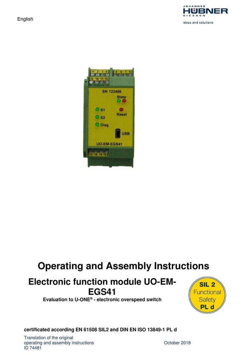
Hubner UO-EM-EGS41 Operating and assembly instructions
