6. WLAN antenna - This is he antenna for wireless LAN.
7. USB connector - The two connectors are USB hosts with support for mass storage de-
vices.
Currently, there is no auto detection for plugged in devices; the devices will need to be
manually mounted.
8. Zigbee module - this is a Zigbee static controller which can monitor/control other Zigbee
based devices/sensors.
9. Push button 1 - this push button’s state is accessible via GPIO pin 4. If depressed before
system power on (or software reboot), system enters download mode. This mode is used
by SerComm during mass production, if board is accidentally booted into this mode,
power off than power back on.
10. Push button 2 - This push button’s state is accessible via GPIO pin 6. If depressed before
system power on (or software reboot), then release during boot up sequence, the LAN,
WAN and wireless LAN settings are restored to default value. However, GPIO pin 6 is
also tied to RESET pin of the Zigbee module. Hence, if push button 2 is depressed during
normal operation, Zigbee functionality may behave unpredictably.
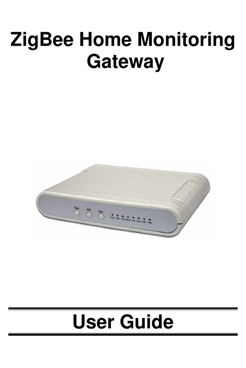
11. Programmable LED - These are seven single coloured and one bi-coloured LED control-
lable by firmware.
12. WPS push button - This button is used for WPS function.
Below is a close up of the console port. The pin definitions are:
Pin 1 - Vcc
Pin 2 - Receive
Pin 3 - Transmit
Pin 4 - Ground
7
