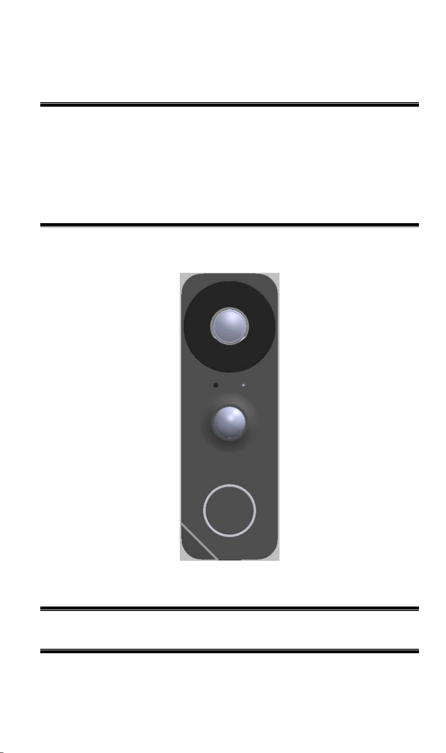
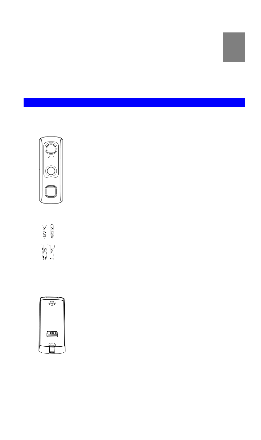
Sercomm SCD2R0-29 User manual

FCC ID: P27SCD2R0
SCD2R0-29
Wireless FHD
Doorbell Camera
Setup Guide

FCC ID: P27SCD2R0
Copyright 2019. All Rights Reserved.
Document Version: 1.1

FCC ID: P27SCD2R0
Table of Contents
Chapter 1 Introduction..........................................................................................................1
Package Contents ..............................................................................................................1
Physical Details..................................................................................................................2
Chapter 2 Setup......................................................................................................................5
System Requirements........................................................................................................5
Installation.........................................................................................................................5
Chapter 3 Hardware Installation.........................................................................................8
Overview ............................................................................................................................8
Power Kit Installation.....................................................................................................11
Always On Bracket Installation (Optional)...................................................................12
Battery Pack Installation (Optional)..............................................................................13
Appendix A Specifications.................................................................................................14
Wireless Doorbell Camera..............................................................................................14
Regulatory Approvals.....................................................................................................15

FCC ID: P27SCD2R0
1
Chapter 1
Introduction
This section provides information about the Doorbell Camera features,
components and capabilities..
Package Contents
The following items should be included: If any of these items are damaged or missing, please
contact your dealer immediately.
1. Doorbell Camera x 1
2. Screw/Anchor x 2
3. Always On Bracket x1(Optional, may not included in the package)
1

FCC ID: P27SCD2R0
2
Physical Details
The SCD2R0-29 supports both analog and digital chimes within 8-24 AC voltage range.
The operation temperature of SCD2R0-29 with regular mounting bracket and Battery pack
is –4°F to 122°F (–20°C to 50°C). As to SCD2R0-29 with Always on bracket, the operating
temperature is –4°F to 104°F. (–20°C to 40°C) on day mode and –4°F to 95°F. (–20°C to
35°C) on night mode.
Note:
1. The Doorbell internal battery will not be charged when the temperature is < 32°F (0°C)
and > 122°F (50°C) or discharge when internal temperature is < -4°F (-20°C) and >138°F
(60°C)
2. The battery of Battery Pack can only be charged 0℃to 35℃, 85% RH Max, and
discharged -20℃to 50℃, 85% RH Max
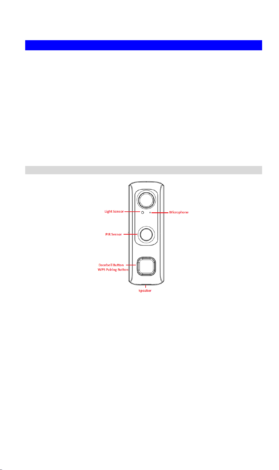
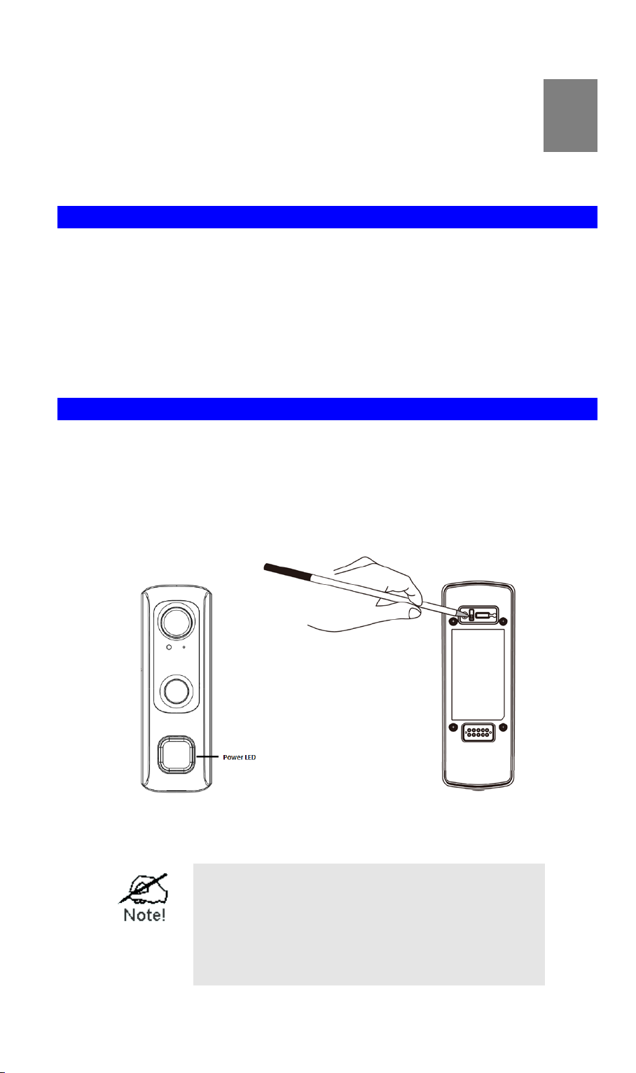
Front Panel
Light Sensor This is hardware sensor to detect LUX.
Microphone The built-in microphone is useful for bi-direction voice
conversation.
PIR Sensor This is hardware sensor to detect motion.
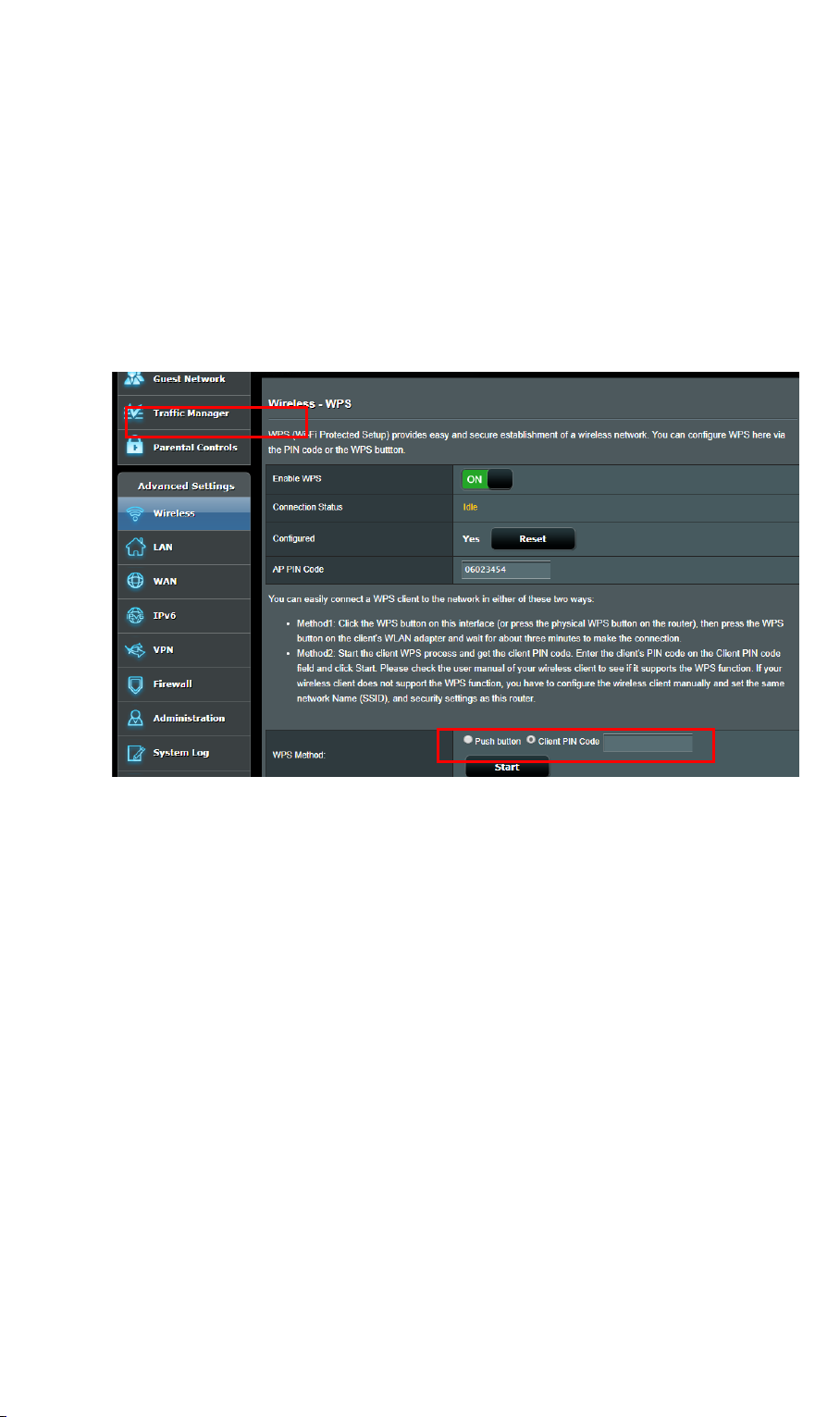
Doorbell/WPS
Pairing Button Doorbell/WPS Button has two functions:
•WPS Pin Code Mode: When doorbell button is held down for
more than 3 seconds, the doorbell camera will be in WPS Pin
Code Mode.
•WPS PBC Mode. When doorbell button is held down for less
than 3 seconds, the Wireless HD Doorbell Camera will be in
the WPS PBC mode (Auto link mode).
Note: When Wi-Fi connection is established, the WPS function
is disabled.
•Doorbell Mode: Press the button to ring the door chime.

FCC ID: P27SCD2R0
3
Rear Panel
Reset Button When pressed and held over 10 seconds, the LED will be solid
amber, which means the settings of camera will be set to their
default values.
On/Off Switch Use this switch to turn on/off the device.
Micro USB Connector This connector is used for charging the power. Connect the
supplied Micro-USB cable to this port.

FCC ID: P27SCD2R0
4
LED Activity & Behavior
Doorbell
Activity
LED
Color
LED
Behavior
Description
Factory Reset
Amber
Solid
Press the reset button for 10 seconds to start
this process.
WPS Pairing
(PIN Code
Mode)
Amber
Blinking
(200ms)
When doorbell button is held down for more
than 3 seconds, the LED will start flashing
amber indicating doorbell camera is trying to
connect to your Wi-Fi network in Pin Code
mode.
WPS Pairing
(PBC Mode)
Amber
Blinking
(500ms)
When doorbell button is held down for less
than 3 seconds, the LED will start flashing
amber indicating doorbell camera is trying to
connect to your Wi-Fi network in PBC mode.
WPS Failure
Amber
Solid
(5s)
If doorbell camera falls during WPS
enrollment, the LED will be solid on for 5
seconds.
Network
Connected
(Boot-up)
Green
Blinking
(500ms)
When the doorbell camera is trying to
connect the network, LED color will change
to blinking green.
USB charge+
Battery < 80%
Blue
Blinking
(1s)
LED spinning blue indicates the camera is
charging for power.
PIR Triggered
Blue
Solid
When PIR detects motion the LED will turn
solid blue.
Doorbell
Button Press
Blue
Solid
NA
Intercom
Green
Whirling
(2s)
Green LED will pulse between dim and
medium intensity for two seconds while
waiting for interactive session.

FCC ID: P27SCD2R0
5
Chapter 2
Setup
This Chapter provides details on how to install and configure the Doorbell
Camera.
System Requirements
•A computer with Internet access
•You can use the following web browser while using a computer:
• Internet Explorer 10 or later
• Firefox 3.5 or later
• Safari 3 or later (Mac OS X only)
• Chrome
• Microsoft Edge
Installation
1. Power-Up and Check LED
Turn on the switch on the rear side of the doorbell camera and wait for 20 seconds until
the LED turns to flashing amber.
Note: The internal battery supports about 40 minutes of operation. If you don’t see the
camera powering up, please charge the doorbell camera via Micro USB cable with USB
charger (DC5V1A or above ) for 45 minutes before installation.
2. Add the Doorbell Camera to your network.
a. Doorbell will detect the Wireless device (AP or router) which is Disable the Wireless
Security automatically.
The default Wireless settings are:
Mode: Infrastructure
SSID: ANY
Wireless Security: Disabled
Domain: USA
Channel No.: Auto
2

FCC ID: P27SCD2R0
6
b. 1) WPS PBC Mode:Press the Doorbell button for less than 3 second and on your
Wireless device (AP or router) as well to establish a wireless connection
automatically. The wireless connection is successful when the Green LED blinking.
2) WPS Pin Code Mode:Key in the PIN code of Doorbell’s back label on the
Client PIN code of AP, and then held down Doorbell button for more than 3 seconds,
the Doorbell Camera will be in the WPS Pin Code mode.
(Please make sure if your AP or router support the WPS Pin code mode)
Note: Once Doorbell ever connected to AP by WPS or GUI configuration, then the
push button is no longer for WPS function.
Please restore the Doorbell to factory default on working mode, after then try
the WPS again to connect another AP.
c. Obtain the IP Address of Doorbell on Wireless device (AP or router) device page.
And start the Internet Explorer. After then enter the IP Address of Doorbell on the
Address box of Internet Explorer (ex. http://192.168.1.223)
d. When you connect, the following screen will be displayed.
e. Click View Video.
f. The first time you connect to the camera, you will be prompted to install decoders.
Choose "I accept the terms of the license agreement" and click "OK".
Note: The options can only be configured while using IE browser. Other browsers can
just view the video rather than configuration.

FCC ID: P27SCD2R0
7
g. Video will start playing automatically. There may be a delay of a few seconds while
the video stream is buffered.
h. If the Administrator has restricted access to known users, you will then be prompted
for a username and password.
Enter the name and password assigned to you by the Doorbell administrator.
The default log in Administration:
User Name: administrator
Password: Blank
i. Access the Administration for more Doorbell settings on SCD2R0-29 GUI.
3. Switch to analog or digital chime according to your existing doorbell in the process.
(The default chime which SCD2R0-29 support is analog type; the customers are required
to develop this feature on the App)

FCC ID: P27SCD2R0
8
If your existing doorbell produces an electronic sound that is programmable
and comes in the form of a unique sound, it's a digital chime. If it has a
traditional "ding dong" sound, it's a compatible analog chime.
4. Complete the pairing process and unplug the Micro USB cable from the
Doorbell Camera.
5. Identify the location for Mounting the Doorbell Camera
The recommended installation height of the Doorbell Camera is about 130~150cm from
the ground. Please refer to Chapter 3 Hardware Installation for more details.
Chapter 3
Hardware Installation
This chapter covers the most likely problems and their solutions.
Overview
Note: Ensure the camera is configured and enrolled in AP or router before permanently
mounting.
Note: If SCD2R0-29 is using for engineering develop purpose, it is available to use Mirco USB
cable to charge the battery for replacing the transformer. And doorbell does not require
attaching with the chimer.
1. Check the voltage at the chimer to ensure voltage is between 8 ~ 24V AC.
2. Turn off the breaker circuit before disconnecting legacy doorbell button.
3. Unscrew the legacy doorbell to locate two power wires. (The recommended installation
height is between 47 -60 inches.)
3

FCC ID: P27SCD2R0
9
4. Choose either the Always On bracket or the regular mounting bracket that will cover the
hole of the legacy doorbell button.
Please check Always On Bracket Installation section for more details
5. Connect the power wires from the existing doorbell to the screw terminals of the bracket.
6. Secure the bracket with screws.
Note: Install the anchors if necessary. The provided lever can be used for measuring
angles to prevent inclination.
7. Attach the doorbell camera to the mounting bracket. Make sure the doorbell camera is
firmly fixed and working properly.
Caution: To avoid damaging the rubber seal of the pogo pins, please attach the camera to
the mounting bracket flush. Mounting bracket should lay flat against the wall. Over
torqueing can warp the bracket and cause it to lose contact with pins.

FCC ID: P27SCD2R0
10
8. Turn on the breaker circuit.
9. Check that the chime is working normally by pushing the doorbell button. If the AC wires
are not connected properly, the LED will blink amber every 5 seconds.

FCC ID: P27SCD2R0
11
Power Kit Installation
The Power Kit included with the doorbell camera is a small device, which support Doorbell
with any kinds of analog and digital chime usage by going between the doorbell transformers
and chime wiring.
Note: Before removing or attaching wires to your original bell, be sure that the power is turned
off at the breaker box. Consult a licensed electrician if needed.
1. Turn off the circuit breaker for the indoor chimer.
2. Remove the cover from the indoor chimer.
3. Loosen the "Front" and "Trans" terminal screws on the indoor chimer.
4. Connect white wire from the Power Kit to the “Front” terminal, and the black wire to the
“Trans” terminal, leaving the existing doorbell wires in place. Then, re-tighten the screws.
5. Position the Power Kit inside your indoor chimer, away from any moving parts. Use the
adhesive (foam tap) on the back of the Power Kit to fix it in place, if desired.
6. Attach the cover back to the indoor chimer, and turn the power on at the breaker.

FCC ID: P27SCD2R0
12
Always On Bracket Installation (Optional)
The Always On bracket (may not included in the package) can only be installed with
mechanical doorbell chimes (AC16V~24V). In this configuration, the doorbell camera will be
in always on mode, which brings back the 5 second pre-buffer, connects live view faster, and
removes the need for the internal battery to be charged.
1. Use the always on bracket that will cover the hole of the legacy doorbell button.
2. Connect the power wires from the existing doorbell to the screw terminals of the bracket.
3. Secure the bracket with screws.

FCC ID: P27SCD2R0
13
4. Attach the doorbell camera to the mounting bracket. Make sure the doorbell camera is
firmly fixed and working properly.
Caution: To avoid damaging the rubber seal of the pogo pins, please attach the camera
to the mounting bracket flush. Mounting bracket should lay flat against the wall. Over
torqueing can warp the bracket and cause it to lose contact with pins.
Specification
LED LED x 1 (Green)
Waterproof Enclosure IP65
Pogo Pin 2 x 4 (8 Pin)
Power AC16~24V
Doorbell Attached Always on Bracket LED Activity & Behavior
Doorbell
Activity
LED
Color
LED
Intensity
LED
Behavior
Description
Bracket
Connected
Blue
Dim
Solid
After connected to the doorbell, LED color
will turn to dim blue.

14
Appendix A
Specifications
Wireless Doorbell Camera
Model Wireless 2-Way Doorbell Camera
Dimensions
(H x W x D) 126 mm * 42.7mm * 35.2mm (4.96 x 1.68 x 1.39)
Operating Temperature Mounting Bracket and Battery Pack mode: -20°C to 50°C
Always On Bracket mode:
-20ºC to 40ºC ( Day Mode)
-20ºC to 35ºC ( Night Mode)
Storage Temperature -20°C to 45°C
Network Protocols TCP/IP, HTTP, HTTPS, DHCP, uPnP, NTP, RTP, RTCP, RTSP,
DN
Wireless 802.11 b/g/n
IR LED 1
LED 1
Microphone Built-in Microphone
Button Doorbell/WPS Button x 1
Reset button x 1
Speaker 1 built-in Microphone
Power Adapter USB charger:DC 5V,1A
Internal Battery Power : capacity 730mA
Charging Temp : 0ºC to 20ºC
A

15
Regulatory Approvals
FCC Statement
This equipment generates, uses and can radiate radio frequency energy and, if not installed and
used in accordance with the instructions, may cause harmful interference to radio
communications. However, there is no guarantee that interference will not occur in a particular
installation. If this equipment does cause harmful interference to radio or television reception,
which can be determined by turning the equipment off and on, the user is encouraged to try to
correct the interference by one of the following measures:
•Reorient or relocate the receiving antenna.
•Increase the separation between the equipment and receiver.
•Connect the equipment into an outlet on a circuit different from that to which the receiver
is connected.
•Consult the dealer or an experienced radio/TV technician for help.
To assure continued compliance, any changes or modifications not expressly approved by the
party responsible for compliance could void the user's authority to operate this equipment.
(Example - use only shielded interface cables when connecting to computer or peripheral
devices).
FCC Radiation Exposure Statement
This equipment complies with FCC RF radiation exposure limits set forth for an uncontrolled
environment. This equipment should be installed and operated with a minimum distance of 20
centimeters between the radiator and your body.
This device complies with Part 15 of the FCC Rules. Operation is subject to the following two
conditions:
(1) This device may not cause harmful interference, and
(2) This device must accept any interference received, including interference that may cause
undesired operation.
This transmitter must not be co-located or operating in conjunction with any other antenna or
transmitter.
CE Approval
CE Standards
This product complies with the 99/5/EEC directives, including the following safety and
EMC standards:
•EN55022/24
CE Marking Warning
This is a Class B product. In a domestic environment this product may cause radio
interference in which case the user may be required to take adequate measures.
This manual suits for next models
1
Table of contents
Other Sercomm Security Camera manuals

Sercomm
Sercomm RC8520 User manual

Sercomm
Sercomm OC835-ADT User manual

Sercomm
Sercomm BC855 User manual

Sercomm
Sercomm iCamera OC825 User manual

Sercomm
Sercomm RC8110 User manual

Sercomm
Sercomm DBC831 User manual

Sercomm
Sercomm RC8522 User manual

Sercomm
Sercomm XHC3 User manual

Sercomm
Sercomm RC8221 User manual

Sercomm
Sercomm RC8111 User manual
Popular Security Camera manuals by other brands

Sanyo
Sanyo VCC-HD5600 - Full HD 1080p Day/Night Pan-Tilt-Zoom... Specifications

Security Camera King
Security Camera King CVIOD-EL2MPIR50 user manual

TP-Link
TP-Link tapo C425 quick start guide

Sony
Sony XC-ST51 Technical manual

Axis
Axis P3367-VE user manual

Withings
Withings Home Installation and operating instructions