USER MANUAL
Cabinet Maintenance — All Models
Keeping the casters free of dirt build-up will go a long way in prolonging their life. Additionally, periodic tightening of door latch
and hinge screws may be required.
BASIC TROUBLESHOOTING
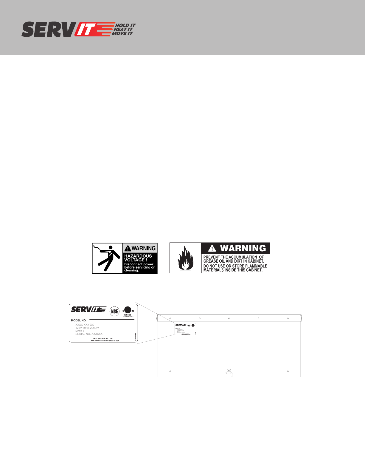
WARNING: Only factory approved service agents must attempt to service, repair or replace electrical components, wiring or
power cord.
1. Controls do not work (no heat being generated or fan does not run):
• Check that the cabinet is plugged-in.
• Check that the outlet has power.
• Check that the power switch is in the “On” position.
• Check the cabinet wiring from the power cord to the power switch and to the thermostat.
• For holding, make sure in HOLD mode. For proofing, make sure in PROOF mode.
2. Temperature too hot:
a. During initial pre-heat, cabinet may overshoot set point.
b. If displayed temperature exceeds 220°F (104°C):
• Blower wiring is faulty or disconnected. Blower needs replacing.
• The thermostat may have failed and the thermal cut-out device is controlling the temperature.
• Thermal cut-out device may have failed.
3. Temperature too low:
a. The cabinet may still be in pre-heat or recovering from the door being opened.
b. Door is not closed or sealing properly.
c. Worn out door gasket. Replace gasket.
d. Blower is not circulating air:
• Blower wiring is faulty or disconnected.
4. No heat generated
When power is on and in HOLD mode, amp draw for 120V units should be approximately 16 amps and In PROOF mode, 120V
amp draw should be approximately 6.0 amps.
• Air heater element may be faulty.
• The wiring to the air heater element may be faulty or disconnected.
• Thermostat may be faulty.
• The thermal cut out may be open or have a disconnected wire coming to it or going from it to the element.
Regularly inspect the casters. Tighten loose fasteners and replace worn or damaged
parts with new SERVIT approved parts. Replace worn or damaged casters immediately.
Additionally, periodic tightening of door latch and hinge screws may be required.
5