3
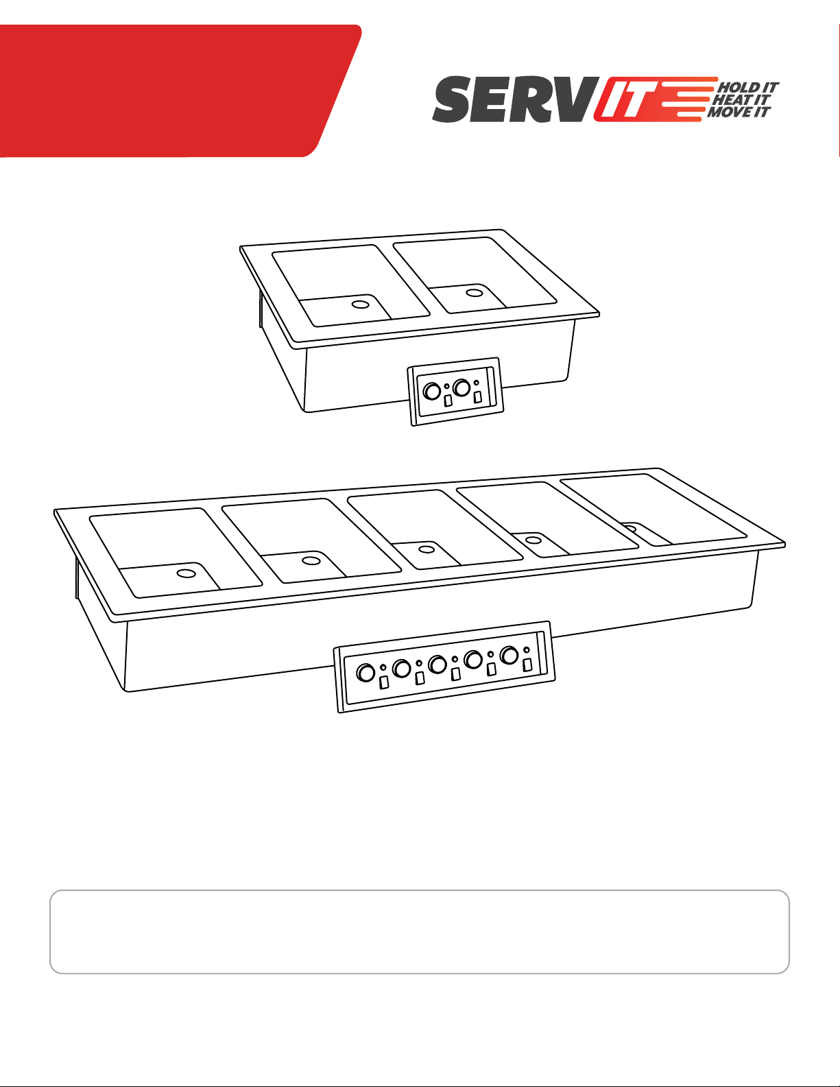
DROP-IN HEATED WELLS
USER MANUAL
INTRODUCTION
Servit Drop-In Warmers are designed to keep foods at optimum serving temperatures without affecting quality. Perfect for
commercial environments such as buffets, serving lines, and corporate cafeterias, these warmers hold anything from vegetables to
pastas, fried chicken, and more!
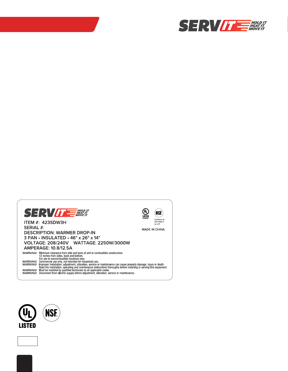
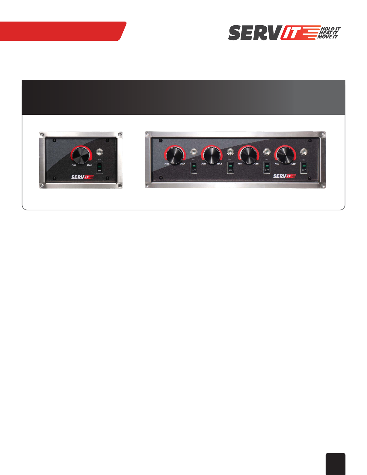
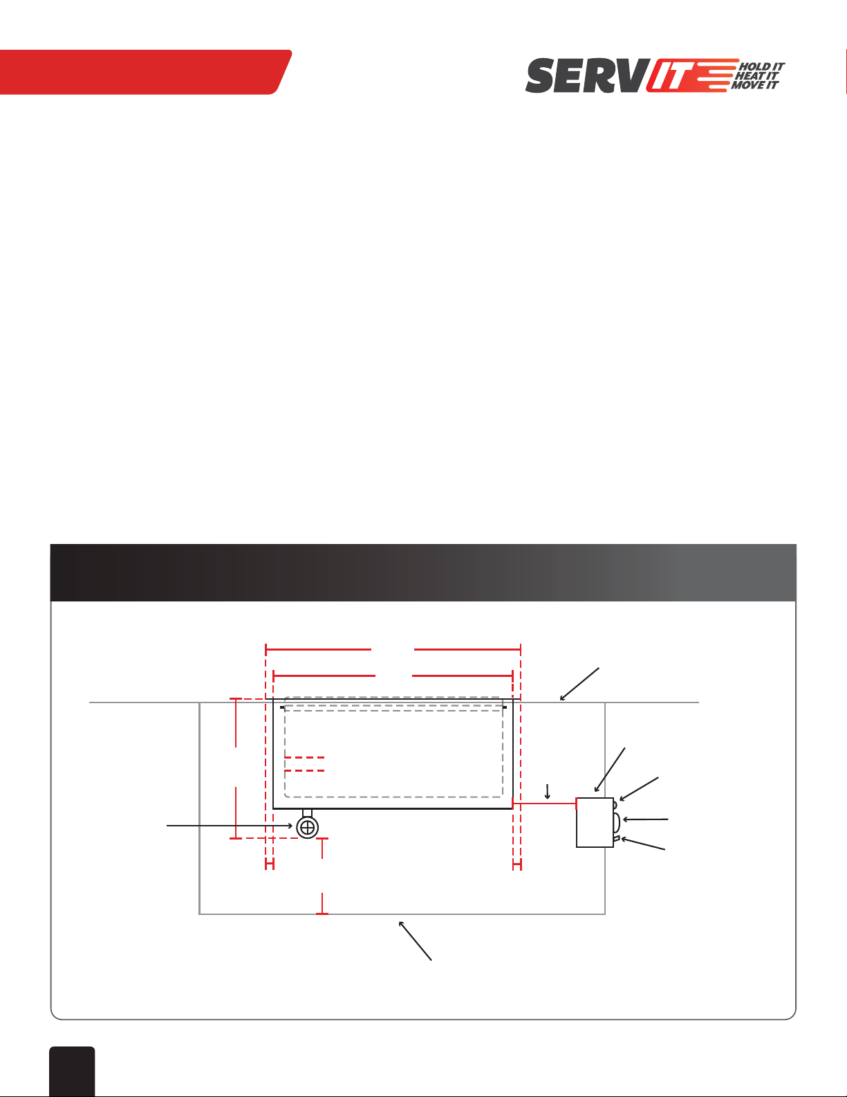
All models include standard features such as thermostatic controls and drains with screens to prevent food waste from entering
your plumbing waste line. The drains are a ¾” NPT drain, allowing for quick draining during end of day cleaning. They are built for
tough front and back of house use with rugged stainless steel construction and heavy-duty hardware. ServIt warmers come with
robust 18-gauge 304 stainless steel top and well liner and 20-gauge 430 stainless steel exterior, perfect for resistance to corrosion
while being easy to clean. These warmers were designed with the fabricator and installer in mind, providing simplified installation
over competitors.
This manual provides the installation, safety, and operating instructions for Drop-In & Top-Mount Warmers. ServIt recommends all
installation, operating, and safety instructions appearing in this manual be read prior to installation or operation of the unit.
SAFETY WARNINGS
ServIt Heated Drop-In Food Wells are designed, built, and sold for commercial use and should be operated by trained personnel
only. Clearly post all CAUTIONS, WARNINGS, and OPERATING INSTRUCTIONS near each unit to ensure proper operation and to
reduce the chance of personal injury and/or equipment damage.
WARNING: Do not store or use gasoline or other flammable vapors and liquids in the vicinity of this or any other appliance. Keep the
area free and clear of combustible materials.
WARNING: Improper installation, adjustment, alteration, service, or maintenance can cause property damage, injury, or death. Read
the Installation, Operating, and Maintenance Instructions thoroughly before installing or servicing this equipment.
CAUTION: These models are designed, built, and sold for commercial use only. If these models are positioned so the public can use
the equipment, make sure all cautions, warnings, and operating instructions are clearly posted near each unit so that
anyone using the equipment can use it correctly and not injure themselves or the equipment.
CAUTION: Make sure food product has been heated to the proper food-safe temperature before placing in unit. Failure to heat food
product properly may result in serious health risks. This unit is for holding preheated food product only. Unit is not meant
to rethermalize cold or chilled product.
CAUTION: Locate unit in an area that is convenient for use. The location should be level and strong enough to support the weight of
the unit and contents.