Sesino MSG 84 Series User manual

USE AND MAINTENANCE
MANUAL
SHELL AND TUBE HEAT EXCHANGER WITH INSPECTABLE
AND WITHDRAWABLE TUBE BUNDLE FOR WATER-OIL
MSG 84 & MSG 134 SERIES

USE AND
MAINTENANCE
MANUAL
Shell and tube heat
exchanger with
withdrawable tube
bundle for water-oil
series MSG
p. 2
1. INTRODUCING 3
2. WARNING 3
2.1 Identification label 4
3. TECHNICAL SPECIFICATIONS 5
4. INSTALLATION 7
5. PERIODIC MAINTENANCE 9
5.1 Internal cleaning 9
5.1.1 Shell side cleaning 9
5.1.2 Tube side cleaning 10
5.2 Zinc anode inspection and replacement 10
5.3 Cover removal 11
5.4 Tube bundle withdrawal 13
6. SPARE PARTS AND INTERNAL COMPONENTS 15
7. TAMPERING 20
8. STORAGE 20
9. WASTE DISPOSAL 20
INDEX
USE AND
MAINTENANCE
MANUAL
Shell and tube heat
exchanger with
withdrawable tube
bundle for water-oil
series MSG
p. 3
1. INTRODUCTION
2. WARNING
This manual must be considered an integral part of the heat exchanger and must be stored toge-
ther with it throughout the exchanger‘s useful life.
Read the manual carefully before installing the heat exchanger.
The manual contains important safety information.
a) The heat exchanger should only be intended for the use for which it was designed. Any
other use could cause damage to property and people and therefore the manufacturer
disclaims all responsibility for accidents arising from its misuse.
c) Fluid pressures and flow rates must be within design limits to avoid vibration, erosion
and in some cases breakage of parts most affected by the dynamic action of fluids.
b) The exchanger shall be used for operating conditions (pressures and temperatures) and
for fluids for which it has been calculated both thermally and mechanically and for which
chemical compatibility has been assessed (see par. 3). In case of operating conditions
other than calculation conditions, the performance of the exchanger changes and it is pos-
sible to even cause very serious damage to the device.
d) Before connecting the oil side and cooling water side feeds, verify that the hydraulic
circuit complies with the performance of the heat exchanger.

USE AND
MAINTENANCE
MANUAL
Shell and tube heat
exchanger with
withdrawable tube
bundle for water-oil
series MSG
p. 4
e) Do not touch the heat exchanger while operating. During exercise some external surfa-
ces of the same may be very hot.
The manufacturer disclaims all liability for any damage to property and people due to non-com-
pliance with these instructions or misuse or modifications made by unauthorized personnel.
Each heat exchanger is provided with an adhesive identification label. It shows the manufacturer,
the model type, the number of internal baffles, the unique serial number of the heat exchanger, the
design pressure (relative), the hydrostatic test pressure (relative) (they are both for the tube and
shell side), the thermal heat exchanged in 4 configurations at different flow rate.
Figura 1: esempio di targa dati identificativa MSG
f) Do not remove the identification label (see par. 2.1) of the heat exchanger. On it are
reported the technical data of the product and the contractual references that allow the
traceability of the same. It is considered an integral part of the exchanger and must remain
clearly visible on the same.
2.1 IDENTIFICATION LABEL
USE AND
MAINTENANCE
MANUAL
Shell and tube heat
exchanger with
withdrawable tube
bundle for water-oil
series MSG
p. 5
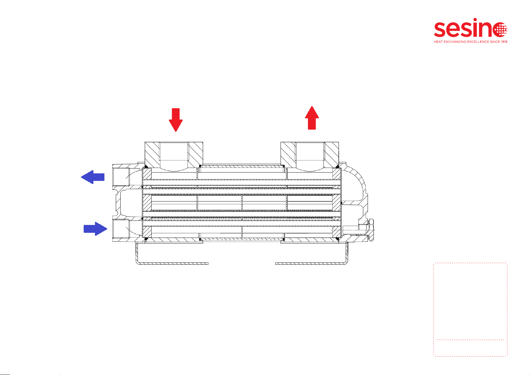
The MSG series heat exchanger is a shell and tube type of heat exchanger. It has a withdrawable
tube bundle. It is designed for heat exchange between water and oil (or similar) fluids. It has 4
passes on the tube-side. Its working principle is represented in the following figure.
The following are the main features of operation:
• Hot fluid max. input temperature: 120°C
• Cold fluid max. input temperature: 70°C
• Operating fluids: Mineral oil, Synthetic oil, Water Emulsified water, Glycol water
• Maximum operating pressure: 12 bar
Please note: contact our technical office in case of special applications.
Figure 2: MSG heat exchanger working principle
3. TECHNICAL SPECIFICATIONS
MANUALE USO E
MANUTENZIONE
Scambiatore di calore
fascio tubiero estraibile
acqua-olio serie MSG
Pag. 5/20
3. CARATTERISTICHE TECNICHE
Lo scambiatore di calore della serie MSG è un tipo di scambiatore di calore del tipo a fascio
tubiero. Ha un fascio tubiero di tipo estraibile. È progettato per lo scambio di calore tra acqua
e olio (o fluidi simili). Ha 4 passaggi sul lato tubi. Il suo principio di funzionamento è
rappresentato nella figura seguente.
Figure 1: principio di funzionamento scambiatore di calore MSG
Di seguito sono riportate le caratteristiche principali di funzionamento:
•Temperatura max. ingresso fluido caldo:
120°C
•Temperatura max. ingresso fluido freddo:
70°C
•Fluidi operativi:
Olio minerale
Olio sintetico
Acqua
Acqua emulsionata
Acqua glicole
•Pressione massima di esercizio:
12 bar
N.B.: contattare il nostro ufficio tecnico in caso di applicazioni speciali.

USE AND
MAINTENANCE
MANUAL
Shell and tube heat
exchanger with
withdrawable tube
bundle for water-oil
series MSG
p. 6
When the final application machine, in which the heat exchanger is installed, is running at full spe-
ed, it is necessary to check that the right flow rate of water circulates in the heat exchanger. This
can be done easily by controlling its thermal increase which should not be too low (too high flow
rate), nor too high (low flow rate).
It is a good rule to consider a thermal increase of 10 C when the temperature of the incoming
water is 20 C and a thermal increase of 5 C with higher water temperatures. Usually the flow rate
of water varies from about half that of the oil to the flow rate of the oil, depending on the tempe-
rature you want to obtain at the exit. To increase the heat dissipated by the exchanger, you can
increase the flow rate of cold water.
It is also advisable to prevent the water speed from being too slow inside the heat exchanger be-
cause, when its temperature exceeds 50 C, the limescale contained in it begins to settle appreci-
ably reducing the section available inside the tube sections. In order to avoid erosive phenomena,
however, the water speed must not be too high. As a reference, the optimal water speed is around
2.5 m/s (corresponding to a flow rate of 45 LPM for MSG 84 and 125 LPM for MSG 134).
If these values affect the heat exchange, contact our Technical Office for a thermodynamic verifi-
cation of the final application.
It is possible that in hydraulic circuits there may be sudden pressure peaks (water hammer) that
could approach or exceed the maximum permissible pressure from the exchanger, resulting in fluid
leaks. These pressure changes are very rapid and are therefore not detected by common pressure
gauges, which can only measure static pressure, but not dynamic pressures; In addition, the over-
pressure valves are not even able to reveal such pressure changes. If it is not possible to contain
this phenomenon, it is considered appropriate to feed the heat exchanger decoupled from the
hydraulic network source of these disturbances, by means of a dedicated circuit with an autono-
mous recirculation pump.

USE AND
MAINTENANCE
MANUAL
Shell and tube heat
exchanger with
withdrawable tube
bundle for water-oil
series MSG
p. 7
Water-oil heat exchangers are generally installed in the return circuit.
It is also possible to make a separate circuit with an autonomous pump and this is advisable in case the oil
flow rates at the discharge are very variable. This results in an improvement in thermal efficiency.
The connection of the water and oil fittings must be carried out in such a way that the air can be easily
ejected with the normal circulation of fluids.
This means that if the exchanger is installed in a horizontal position (see Figure 2, Figure 3) up, while, if
installed upright, the water fittings must be at the top and the oil must enter the fitting as low as possible.
Make sure that the exchanger is installed through its support feet (see Table 1 pos. 6) on a suitable support
structure to withstand its weight, through the 4 anchor points provided as indicated in the general design
of the heat exchanger (the weights and measurements of each model are shown in the catalog).
Warning: do not leave the exchanger suspended or fixed only through the inlet and outlet fittings of the
heat exchanger, since hydraulic vibrations can break them; always ensure that the heat exchanger is fixed
using its own installation support feet (pos. 6) at the 4 expected anchor points.
Warning: in case valves, heavy pipes or other hydraulic components are present on the circuit near the
exchanger fittings, always ensure that their weight is supported independently of the heat exchanger, sin-
ce vibrations can damage the inlet and outlet fittings; the exchanger is not suitable to support suspended
masses of the hydraulic circuit whose weight must be supported regardless of the exchanger.
Warning: do not couple to the input and output connections of the heat exchanger (which have cylindrical
(or parallel, ISO 228-1, G) female thread), other types of different thread; in particular do not insert connec-
tors with male conical gas thread (or taper thread ISO 7, EN 10226, R), since the cylindrical female alumi-
nium fittings of the exchanger can easily be damaged by screwing a conical male steel connector, with a
minimum tightening torque and may no longer guarantee the seal because of permanent deformation or
breakage of the aluminium female thread.
4. INSTALLATION
USE AND
MAINTENANCE
MANUAL
Shell and tube heat
exchanger with
withdrawable tube
bundle for water-oil
series MSG
p. 8
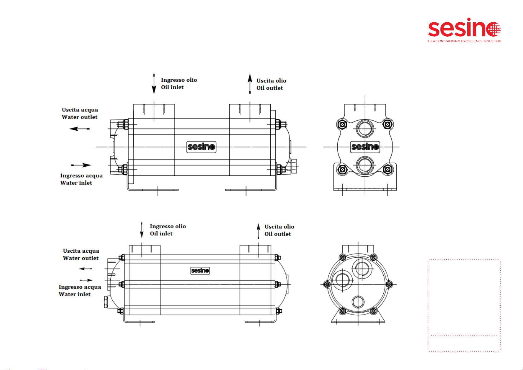
The inlet and outlet fluids should normally be connected to the heat exchanger as shown in the
following figures:
MANUALE USO E
MANUTENZIONE
Scambiatore di calore
fascio tubiero estraibile
acqua-olio serie MSG
Pag. 8/20
L’ingresso e l’uscita dei fluidi di scambio termico vanno normalmente collegati come indicato
nelle seguenti figure:
Figura 2: installazione MSG 84
Figura 3: installazione MSG 134
MANUALE USO E
MANUTENZIONE
Scambiatore di calore
fascio tubiero estraibile
acqua-olio serie MSG
Pag. 8/20
L’ingresso e l’uscita dei fluidi di scambio termico vanno normalmente collegati come indicato
nelle seguenti figure:
Figura 2: installazione MSG 84
Figura 3: installazione MSG 134
Figure 4: MSG 134 installation
Figure 3: MSG 84 installation

USE AND
MAINTENANCE
MANUAL
Shell and tube heat
exchanger with
withdrawable tube
bundle for water-oil
series MSG
p. 9
5.1. Internal cleaning
Depending on the needs and type of final application it is always good practice to check the heat exchan-
ger at regular intervals of operation to prevent the limescale from completely filling internally the pipes or
from corrosive deposits on the thermal exchange surfaces of the internal tubes, which compromise their
efficiency.
You can internally clean the exchanger in several ways. The exchanger does not necessarily have to be dis-
assembled. In fact, it is always possible to do an easier cleaning by circulating a cleaning product or solvent
suitable for the type of fouling and the type of fluid, for a time that can vary from 10 to 30 minutes, even
alternating the sense of flow.
In the case of low clogging due to limestone, it is advisable to circulate, in the opposite direction to the
normal flow, a solution of 15% hydrochloric acid in water, or other similar fluids available on the market.
Alternatively, for more effective mechanical cleaning, it is recommended to proceed as follows in the follo-
wing paragraphs.
Warning: during these operations, Costante Sesino S.p.A. recommends compliance with anti-pollution re-
gulations and to use the appropriate services for the collection and disposal of spent oils and all contami-
nated water.
Warning: You need to be very careful when using chemical cleaning fluids. Carefully follow the supplier‘s
instructions and use skin and eye protection systems. When expected to use a respirator.
5.1.1. Shell side cleaning
For more effective cleaning on the shell side, brushes or jets of water / steam under pressure should be
used, after extracting the tube bundle (pos. 1). To withdraw the tube bundle, follow the indications in par.
5.4 .
Special care must of course be taken in manipulating the tube bundle so as not to damage the tubes and
to provide adequate supports to avoid bending along the long tube bundles.
5. PERIODIC MAINTENANCE

USE AND
MAINTENANCE
MANUAL
Shell and tube heat
exchanger with
withdrawable tube
bundle for water-oil
series MSG
p. 10
5.1.2. Tube side cleaning
For the inspection of the corrosion status and cleaning of the heat exchanger on the tube side, it is
necessary to remove both covers (follow par. 5.3); it is not necessary to withdraw the tube bundle.
For cleaning internally the tubes, brushes can be used and inserted inside the tubes, the internal
diameter of which is 5.5mm.
Before remounting the covers, it is necessary to check that the zinc anode (pos. 12) is intact and
clean; otherwise, it cannot perform its corrosion protection function and it shall be replaced (see
para. 5.2). If the zinc anode is consumed in a short time, it is essential to check the efficiency of
the grounding of the machine on which the exchanger is installed, because the presence of stray
currents could cause corrosive phenomena too.
5.2. Zinc anode inspection and replacement
The sacrificial zinc anode (pos. 12) is placed within the water circuit on the tube side, with the
function of protecting the materials from corrosion, by cathode protection with galvanic coupling
of the less noble zinc metal, which acting as an anode, corrodes instead of the other metals of the
heat exchanger.
Periodically the zinc anode should be inspected, to check the state of wear. If the anode is covered
with a white layer of oxide (or even missing because it is completely corroded), it must be repla-
ced, since the oxide acts as an electrical insulation, inhibiting the protective function of the anode.
To inspect the zinc anode, you can remove the zinc anode plug from the cover (pos. 12), using a
tool. The zinc anode is locked inside the plug by interference fixation on its diameter. For its re-
placement, remove it from the plug and insert a new one of the same diameter (MSG 84: 9, MSG
134: 10.4), always by interference fixation.
Warning:Before removing the zinc anode, make sure that the water circuit is not under pressure.
USE AND
MAINTENANCE
MANUAL
Shell and tube heat
exchanger with
withdrawable tube
bundle for water-oil
series MSG
p. 11
5.3 Cover removal
Below is the procedure for removing the head cover (pos. 4) or bottom cover (pos. 5):
1. Only for head removal (pos. 4) remove incoming and outgoing water fittings.
2. Unscrew the fixing bolts to the ground on the supporting feet (pos. 6).
3. Unscrew and remove M8 nuts (pos. 14).
4. Remove the supporting feet (pos. 6).
5. Remove the cover (pos. 4, 5).
6. Remove the O-Ring (pos. 8) which shall be always replaced before the cover is reassembled.
To keep the manifold stationary and the shell intact during cleaning operations, the manifold can
be blocked by retightening the M8 nuts (pos 14) on the tie rods (pos. 7), without the covers.
Warning: before removing the cover, ensure that the water and oil circuits are not under pressure,
because the oring (pos. 8) is the internal seal on both sides of the exchanger.
Warning: do not attempt to open or disassemble the exchanger head without the unit having been
depressurized, drained and cooled until it is brought to room temperature.
Warning: do not remove the tie rods (pos. 7), nor the manifolds (pos. 3). You can lock the manifold
by retightening the nuts on the tie rods without the covers.
Warning: do not rotate on its concentric axis the tube bundle (pos. 1).

USE AND
MAINTENANCE
MANUAL
Shell and tube heat
exchanger with
withdrawable tube
bundle for water-oil
series MSG
p. 12
Warning: always replace the O-Rings (pos. 8) with new ones before remounting the cover. For
MSG 84: OR 4300 NBR (234) 75.8x 3.53; for MSG 134: OR 4487 NBR (249) 123.4x 3.53.
Warning: the gaskets on the partition plate of the cover (pos. 10, 11) should be replaced if worn
(silicone paste can also be used). Without replacement of these gaskets, there is not any leak, but
there may be a slight decrease in the thermal power exchanged by the exchanger.
Warning: zinc anodes (pos. 12) mounted on covers should always be replaced if worn (see par. 5.2).
After removing the covers, it is not necessary to disassemble the zinc anodes from the covers, for
their inspection.
To reassemble the cover proceed in the opposite direction, taking care to replace the O-Ring (pos.
8) with a new one. After bringing all the nuts to the cover surface, apply the tightening torque of
about 12Nm evenly diagonally (see example below Figure 4 and Figure 5) without over tightening.
MANUALE USO E
MANUTENZIONE
Scambiatore di calore
fascio tubiero estraibile
acqua-olio serie MSG
Pag. 12/20
Per rimontare il coperchio procedere in senso inverso, avendo premura di sostituire l’O-Ring
(pos. 8) con uno nuovo. Dopo aver portato tutti i dadi in battuta, applicare la coppia di
serraggio di circa 12Nm in modo uniforme in diagonale (vedi esempio sotto Figura 4, Figura
5), senza sforzare.
Figura 4: sequenza serraggio MSG 84.
Figura 5: sequenza serraggio MSG 134.
Attenzione: sostituire sempre gli O-Ring (pos. 8) con nuovi prima di rimontare il coperchio.
Per MSG 84: OR 4300 NBR (234) Ø75.8xØ3.53; per MSG 134: OR 4487 NBR (249)
Ø123.4xØ3.53.
Attenzione: le guarnizioni sulla paratia dei coperchi testa e fonda (pos. 10, 11) vanno
sostituite se usurate (può essere usata anche della pasta siliconica). La mancata
sostituzione di queste guarnizioni non comporta alcuna perdita, ma si può verificare un
leggero calo nella potenza termica scambiata dallo scambiatore.
Attenzione: gli anodi di zinco (pos. 12) montati sui coperchi vanno sempre sostituiti se
usurati (vedi par. 5.2). Dopo aver rimosso i coperchi, non è necessario smontare gli anodi
di zinco dai coperchi, per la loro ispezione.
Figure 5: MSG 84 tightening sequence. Figure 6: MSG 134 tightening sequence.

USE AND
MAINTENANCE
MANUAL
Shell and tube heat
exchanger with
withdrawable tube
bundle for water-oil
series MSG
p. 13
5.4. Tube bundle withdrawal
After removing both covers (following the procedure previously detailed in par. 5.3), it is possible
to withdraw the tube bundle (pos. 1), which is no longer constrained by the cover, by applying an
axial force on it. There is no need to remove oil fittings from the shell. Be careful not to move the
manifolds. Follow the steps:
1. Remove a cover.
2. Remove the other cover.
3. Secure the manifolds by screwing the nuts on the tie rods without covers, so that it remains
stationary during the extraction of the tube bundle. It is also possible to re-fixate the heat ex-
changer on the ground frame using the support feet (pos. 6) by remounting them without the
covers, in case it is not possible to hold the exchanger blocked in another way.
4. Gently withdraw the tube bundle without damaging any internal components.
Warning: before removing the tube bundle make sure that the water and oil circuit is not under
pressure.
Warning: after the withdrawal of the tube bundle, handle it very carefully, avoiding damaging it in
all its part; in particular pay attention to the circumferential outer surface of the tubesheet, which
does the pressure seal on the oring.
USE AND
MAINTENANCE
MANUAL
Shell and tube heat
exchanger with
withdrawable tube
bundle for water-oil
series MSG
p. 14
To reinsert the tube bundle inside the heat exchanger, proceed in the opposite direction.
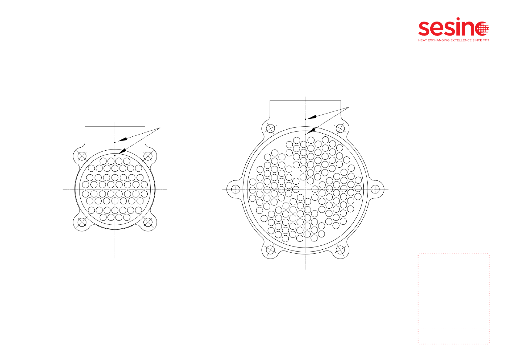
Warning: after reinserting the tube bundle, before remounting the cover, check that the indication
mark on the front side tubesheet is vertically aligned with the vertical indication mark on the front
side manifold, as in the following figures:
MANUALE USO E
MANUTENZIONE
Scambiatore di calore
fascio tubiero estraibile
acqua-olio serie MSG
Pag. 14/20
Per reinserire il fascio tubiero all’interno dello scambiatore procedere in senso inverso.
Attenzione: dopo aver reinserito il fascio tubiero, prima di rimontare il coperchio, controllare
che il segno di indicazione presente sulla piastra lato frontale, sia allineato verticalmente
con il segno di indicazione verticale presente sul collettore lato frontale, come nelle figure
seguenti:
Figura 6: indicatori di allineamento
verticale fascio tubiero / collettore MSG
84.
Figura 7: vista frontale indicatori di
allineamento verticale fascio tubiero /
collettore MSG 134.
Figure 7: MSG 84 vertical alignment indication
marks on tube bundle / manifold.
Figure 8: MSG 134 front view vertical alignment indication
marks on tube bundle / manifold.
USE AND
MAINTENANCE
MANUAL
Shell and tube heat
exchanger with
withdrawable tube
bundle for water-oil
series MSG
p. 15
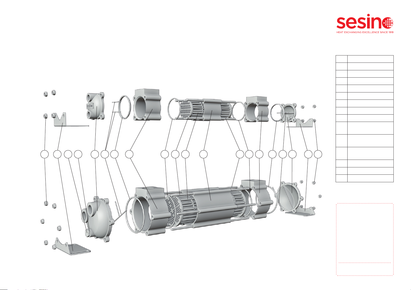
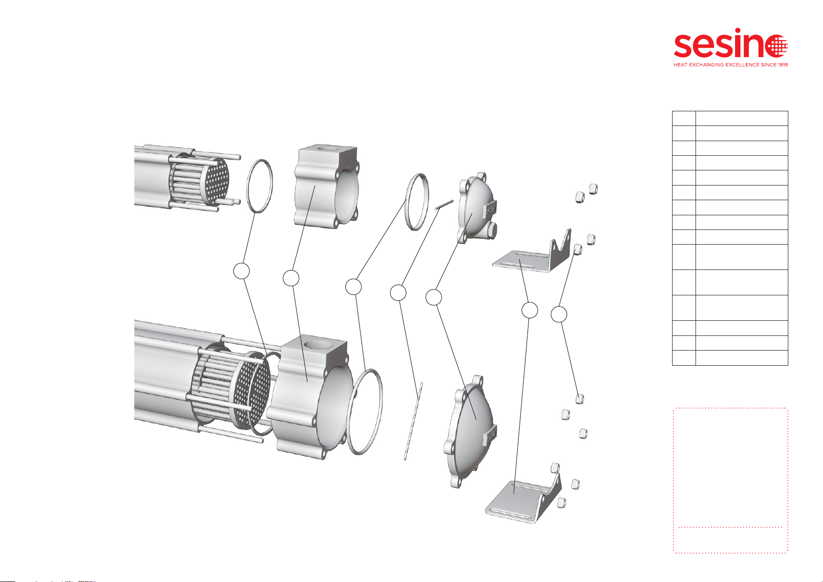
6. SPARE PARTS AND INTERNAL COMPONENTS
Rif. Descrizione
1Tube bundle
2Shell
3Manifold
4Head
5Rear
6Support foot
7Tie rod
8Oring
9Shell manifold
gasket
10 Head passpartition
gasket
11 Rear passpartition
gasket
12 Plug with zinc anode
13 Washer
14 M8 nut
3 31 26 77 88 9 91012 1314
Table 1: Internal component list
45 6 14
Figure 9: MSG 84 exploded viewFigure 10: MSG 84 exploded view
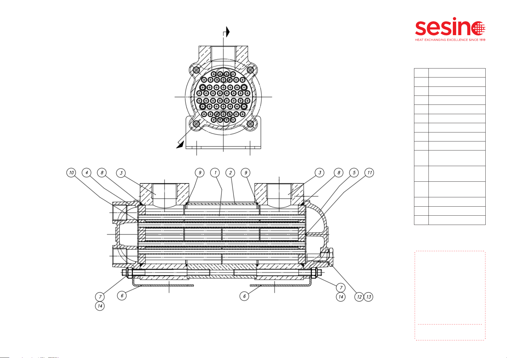
Below is the internal scheme of the heat exchanger with the list of internal components of which it is com-
posed. For any request of spare parts provide the model name on the identification label (see par. 2.1) and
the denomination (see Table 1).
11
USE AND
MAINTENANCE
MANUAL
Shell and tube heat
exchanger with
withdrawable tube
bundle for water-oil
series MSG
p. 16
MANUALE USO E
MANUTENZIONE
Scambiatore di calore
fascio tubiero estraibile
acqua-olio serie MSG
Pag. 16/20
Figura 8: Schema interno MSG 84
Figure 11: MSG 84 internal section
Rif. Descrizione
1Tube bundle
2Shell
3Manifold
4Head
5Rear
6Support foot
7Tie rod
8Oring
9Shell manifold
gasket
10 Head passpartition
gasket
11 Rear passpartition
gasket
12 Plug with zinc anode
13 Washer
14 M8 nut
Table 1: Internal component list

USE AND
MAINTENANCE
MANUAL
Shell and tube heat
exchanger with
withdrawable tube
bundle for water-oil
series MSG
p. 17
MANUALE USO E
MANUTENZIONE
Scambiatore di calore
fascio tubiero estraibile
acqua-olio serie MSG
Pag. 17/20
Figura 9: Schema interno MSG 134
Figure 12: MSG 134 internal section
Rif. Descrizione
1Tube bundle
2Shell
3Manifold
4Head
5Rear
6Support foot
7Tie rod
8Oring
9Shell manifold
gasket
10 Head passpartition
gasket
11 Rear passpartition
gasket
12 Plug with zinc anode
13 Washer
14 M8 nut
Table 1: Internal component list
USE AND
MAINTENANCE
MANUAL
Shell and tube heat
exchanger with
withdrawable tube
bundle for water-oil
series MSG
p. 18
38
9
10
12
13
4
614
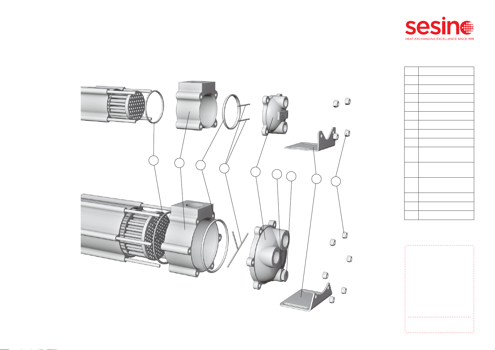
Figure 13: MSG 84 exploded view front sideFigure 14: MSG 134 exploded view front side
In the following figures the exploded view at the front side:
Rif. Descrizione
1Tube bundle
2Shell
3Manifold
4Head
5Rear
6Support foot
7Tie rod
8Oring
9Shell manifold
gasket
10 Head passpartition
gasket
11 Rear passpartition
gasket
12 Plug with zinc anode
13 Washer
14 M8 nut
Table 1: Internal component list
USE AND
MAINTENANCE
MANUAL
Shell and tube heat
exchanger with
withdrawable tube
bundle for water-oil
series MSG
p. 19
In the following figures the exploded view at the rear side:
3
8
9
11 5
614
Figure 15: MSG 84 exploded view rear sideFigure 16: MSG 134 exploded view rear side
Rif. Descrizione
1Tube bundle
2Shell
3Manifold
4Head
5Rear
6Support foot
7Tie rod
8Oring
9Shell manifold
gasket
10 Head passpartition
gasket
11 Rear passpartition
gasket
12 Plug with zinc anode
13 Washer
14 M8 nut
Table 1: Internal component list

USE AND
MAINTENANCE
MANUAL
Shell and tube heat
exchanger with
withdrawable tube
bundle for water-oil
series MSG
p. 20
Any operation to modify the heat exchanger, carried out without prior authorization of Costante Sesino
S.p.A., will automatically result in the decay of the warranty clauses.
The heat exchanger must be stored in a moisture-free environment (HR < 60%) and at a temperature (-10 C
to 40°C), such as to avoid condensation and oxidation to the internal parts of the same. The heat exchanger
can be stored indefinitely in an internal environment.
Warning: Avoid subjecting the heat exchanger or any of its internal components during storage to ambient
thermal cycles.
The heat exchangers of Costante Sesino S.p.A. are built with entirely recyclable materials. Disposal can take
place in compliance with the environment according to local legal requirements in the local area of use.
During maintenance, spent lubricating oil must be disposed of correctly.
7. TAMPERING
8. STORAGE
9. WASTE DISPOSAL
This manual suits for next models
3
Table of contents
Other Sesino Industrial Equipment manuals


