Setec ST-III Series User manual

STIIISeries
POWERSUPPLY
Owner'sManual
PleasereadtheInstallationsectionofthis
manual eforeinstallingtheproduct.

Copyright©SetecPtyLtd2013
Disclaimer
SetecPtyLtdmakesnoclaimastotheaccuracyorsuita ilityoftheinformation
containedinthismanual.SetecPtyLtdacceptsnolia ilityforanylossor
damage,whichmayoccurasaresultofimproperorunsafeuseofitsproducts.
Warrantyisonlyvalidiftheunithasnot eenmodified ythecustomerandhas
not eenmisused.
2

Contents
Introduction..............................................................................................................4
SafetyPrecautions..............................................................................................4
Accessories.........................................................................................................5
Introduction.........................................................................................................5
Operation............................................................................................................5
FunctionalDiagram........................................................................................6
STIIIBasics........................................................................................................6
InstallingTheSTIIIPowerSupply...........................................................................9
WiringUp..........................................................................................................10
Servicing................................................................................................................12
Specifications.........................................................................................................13
BatteryManagement..............................................................................................14
FrequentlyAskedQuestions..................................................................................15
AndersonPlugOperation.......................................................................................16
AftersalesService.................................................................................................17
RepairsandAftersalesService.......................................................................17
WarrantyTermsandConditions........................................................................18
3

Introduction
SafetyPrecautions
PleasereadtheSafetyPrecautionscarefully eforeinstallingthepowersupply.
Besuretoo serveallprecautionswithoutfail.
Aftercompletinginstallation,conductatrialoperationtocheckforfaults.
WARNING
Failure to follow these instructions properly may result in personal
injury or loss of life.
Ensure that there is good ventilation from the battery area.
This appliance is not intended for use by young children or infirm persons without supervision.
Young children should be supervised to ensure that they do not play with the appliance.
Batteries are electrically alive at all times and must be treated with extreme caution. They can
supply high short circuit currents, even if they appear damaged.
Take care that dropping or touching of metal objects onto the battery cell does not cause short
circuits.
Remove any personal metal adornment such as a chain, watch or ring, which could cause
short circuits and personal injury.
CAUTION
Failure to observe these instructions properly may result in property
damage or personal injury, which may be serious depending on the
circumstances.
Refer to the installation section before operating. Correct installation is the most critical factor
in ensuring the safe use of the power supply. If every consideration of these instructions has
been satisfied the power supply will be safe to operate.
Ensure that cable connections to batteries have the correct polarity and are protected against
accidental short circuit.
Ensure that the shrouding supplied with the battery is fitted to the terminals.
Before servicing a battery, disconnect the power supply from the mains supply.
Do not charge non-rechargeable batteries. Failure to do so may result in the battery catching
on fire or possible explosion.
Do not allow water or other liquids to enter the installation area.
4

Accessories
Accessoriesprovidedwiththisproductare:
1. UserManual
Introduction
TheseinstructionsdetailtheinstallationandoperationrequirementsfortheST20
III&ST35IIIpowersupplies.Thesehave eendesignedforoperationinRV’s
providingaDCpowersystem,withoptional attery ackup.
Theunitsoperatefrom240Vacandprovideanisolated13.65Vdcoutputat20A
and35Arespectivelyforpoweringtheloadandchargingof atteries.Allthe
necessaryprotectionandoperatingfeaturesfortheloadand atteriesare
provided.AnoptionalDCinputisalsoprovidedtoena lechargingof atteries
andpoweringoftheloadfromanexternal+13.8VDCpowersource.
Theunitsarefullyenclosedreadyfordirectwallmounting.Allconnectionsareat
therearofunitprovidingconvenientwiringandinstallation.Useraccesstoall
loadand atteryfusinghas eenprovidedfromthefrontoftheunit.
Operation
Safety:Refertotheinstallationsection eforeoperating.Correctinstallationis
themostcriticalfactorinensuringthesafeuseofthepowersupply.Ifevery
considerationoftheseinstructionshas eensatisfiedthepowersupplywill e
safetooperate.
IftheACsupplycordisdamageditmust ereplaced ythemanufacturer,its
serviceagentorsimilarlyqualifiedpersonsinordertoavoidhazard.
Theunitisratedtochargeasingle12V(upto6cells)leadacid atteryat100Ahr
Capacity.
5

FunctionalDiagram
STIIIBasics
AC/DCPowerSupply:Thisprovidesanisolated13.65Vdcoutputforpoweringof
theloadandfloatchargingofthe attery.Batterycurrentissensedandmonitored
ythepowersupplytoensurethatthemaximumchargingcurrentisnot
exceeded.
BatteryFeatures:Thepowersupplyprovidesfull atterymanagementasperthe
following.
Thepowersupplyisafourstage atterychargerwithBoost(VBoost=14.05V),
Float(VFloat=13.65V),Store(VStore=13.25V)andTricklechargemodesto
ensurelong atterylife.
BatteryChargingcurrentislimitedtoamaximumof10A(ST20III)and15A
(ST35III).Thisprovidesoptimumlifeforthe atteries.
Tochargeatthemaximum atterychargecurrenta ove,ensuretheloadcurrent
plus atterycurrentisequalorlessthanthemaximumoutputcurrent.The
chargingcurrentwill ereducedinsituationswherethedifference etweenthe
ratedoutputcurrentandtheloadcurrent(theavaila lechargingcurrent),isless
thanthemaximumchargingcurrent.
Alsonotethatthe atterycurrentsenseisprovidedinthe“Batt+ve” attery
output.Forthisfeaturetowork,theload“+ve”and attery“Batt+ve”shouldnot
ecrossconnected.(Appliancesshouldnot econnectedto oththe“Batt+ve”
and“+ve”terminalsofthepowersupply.Appliancesshould econnectedtothe
“+ve”and“ve”loadterminals).
6
Figure1:FunctionalBlockDiagram
ACInput
8xLoad
Outputs
CaravanBattery
AC/DC
Vadj
BatteryLowvoltage
DisconnectCircuit
LoadRemote
disconnectCircuit
RemoteLoad
on/offInput
Battery–Ve
8xLoad
Returns
CarBattery
BAT– E
BAT+ E
DCIN+ E
– E
L1–L8
LOADSWITCH
BATERYFUSE
LOADFUSES
0.8A
Trickle

Low oltageDisconnection:(LVD)ofthe atteriesisprovidedtopreventdeep
dischargeofthe attery.Automaticreconnectionoccurswhen atteryvoltage
recovers.BatteryCurrentDrainislessthan2mA.
TrickleCharge:TrickleChargetothe atteryisalwayspresent.Whenthe attery
voltageis elowtheLVD(Lowvoltagedisconnect)reconnectvoltage(<10Vand
themainspowerorauxiliarypowerisavaila le,the atterywill echargingat
0.8A.Whenthe atteryvoltageissufficient(>10.5Vforfirstpowerup,11.5Vand
11.7Vforsu sequentreconnectionwithandwithoutmainsrespectively)theLVD
willconnectthe atteryandallowfloatchargingat10A/15A(ST20III/ST35III).
TheTrickleChargefeatureisprovidedtoallow“very”flat atteriesto echarged
atarate,whichwillextendtheirlife.
RemoteBatteryIsolateSwitch:TheSTIIIseriespowersuppliesallowfor
connectiontoaremotelypositionedswitchthatprovidesamanualdisconnection
ofthe atteryfromtheloadsandthemaincharger.Whentheswitchcontactsare
closed,the atterywill eisolatedfromtheloads.
NOTE:Whenthebatteryisisolatedfromtheloadsusingthebatteryisolate
switchitwillNOTchargeatthe10/15Arateevenifthemainsisconnected
tothepowersupply.InthisconditionitwillONLYchargeattheTrickle
chargerate.
FrontPanelIndicators:TheSTIIIseriespowersupplieshave3indicators
visi leonthefrontfascia.
Mains(GREEN)–isilluminatedwhenmainspowerispresent.
Battery(ORANGE)–isilluminatedwhenthe atteryisconnectedtotheloads.
Fault(RED)–isilluminatedwhenthereisafaultwiththepowersupply.
BatteryfuseBlown1
Batteryconnectedreversepolarity2
Shutdowncondition(UVandOT)3
MainPCBmicrocontrollermalfunction4
Notes
1. Flashing1sON,1sOFF.
2. SolidON.
3. Flashing1sON,1sOFF,withnobatteryconnectedthe owersu ly
maybeinhiccu modewhichwillcausetheindicationtoflashwith
randomdutycycleandfrequency.
4. FaultLed=SolidOn,Allotherleds=OFF,irres ectiveofactualmainsor
LVDstatus.
AuxiliaryPowerInput:Thepowersupplyterminal“AuxIn+VE”providesan
alternativeoptionforpoweringoftheloadandfloatchargingofthe atterieswhen
mainsvoltagesarenotpresent.Thisinputisto epowered yasuita le+12V
system.(i.e.CAR).Thevoltageoftheauxiliarypowersourceshouldnotexceed
7

14.8volts.
Whenoperatingviatheexternalinput,currentandvoltagecontrolforthe attery
must eprovidedfromtheexternalsource.TheST20III/35IIIdoesnotprovide
atterycurrentlimitorvoltagecontrolwhenoperatinginthisconfiguration.Trickle
Chargeisstillfunctionalwhenpoweredthrough“AuxIn+VE”terminalofpower
supply.
Suita lefuseprotectionmust eprovidedforthisinput.Afuseratingnot
exceeding20AmpsforST20IIIand30AmpsforST35IIImust eused.
SolarPower:Solarpowershould econnecteddirectlyacrossthe attery
terminalswithavoltageregulatorinseries.Asolarpanelvoltageregulatorwith
maximumoutputvoltagenotexceeding14.8voltsmust eusedatalltimes.
Failuretouseavoltageregulatormayresultinpowersupplyor atterydamage.
Generator:12voltoutputsshouldnot econnectedacross atteryterminalwhilst
atteryisconnectedtopowersupplyorconnectedtothe“AuxIn+VE”terminalof
powersupply.Seriouspowersupplydamageorinternalexplosionmayoccur.If
aflat12volt atteryhasto echargedusingthegenerators12voltoutput,it
shouldfirst edisconnectedfromthepowersupply.Once atteryhas eing
chargeditcanthen ereconnectedtopowersupply.
Protection:Thepowersupplyprovidesautomaticprotectionforoverload
includingshortcircuit,overvoltage,overtemperatureandreverseconnected
attery.InsuchinstancestheFaultindicatorwillilluminateandthepowersupply
willshutdown.Itwillattempttoautomaticallyrestartevery5secondsuntilsuch
casethatthefaultisremoved.
Fusing:Eachloadcircuitandthe atteryhave eenfusedtoprovidefault
protectionanddiscrimination.Refertoservicingsectionformaximumfuseratings.
CAUTION:
Thisapplianceisnotintendedforuse yyoungchildrenorinfirmpersons
withoutsupervision.
Youngchildrenshould esupervisedtoensurethattheydonotplaywiththe
appliance.
Inordertoavoidhazardwhenthesupplycord ecomesdamaged,thecord
mustonly ereplaced ythemanufactureroritsserviceagentorsimilar
technicallyqualifiedperson.
8

InstallingTheSTIIIPowerSupply
HostEquipment:Thehostequipmentmustensurethataccesstotheunit(other
thanthefrontpanel) ytheuserisprevented.
Personnel:Installationisto ecarriedoutonly ysuita lyqualifiedpersonnel.
entilation:Provideaminimumof80mmclearancea ove, elowand ehindthe
unit.Thefinalenclosuremustalsoprovideadequateventilationtotheoutside
world(orlargerinternalcavity)topreventthe uildupofhotair.Failuretoprovide
adequateventilationwillmeantheunitmayprematurelytripthermalshutdown.A
minimumventilationof20,000mm2totheoutsideworldmust eprovided.
CAUTION
Donotinstallunitinsamecompartmentasbatteriesorflammable
materialsuchaspetrol.
Ensurethattheinstallationmeetstheventilationrequirementsabove.
MechanicalandMounting:
Depthofunitis125mm
Aftermountingunit,cliponthefrontfascia(ensurethatalllockingclipshave
engaged)andsecurewithscrewlocatedinsidethefusepaneldoor.
DCca lesmust esizedtocarrythemaximumfullloadcurrentandtonotexceed
thesystemvoltdroprequirements.Thefollowingca lesizesarerecommended.
Orientation:Theunitisto einstalledwiththefrontfasciainaverticalplane.
Failuretodothiswillcauseprematuretemperatureshutdown.
9
Cut-out for mounting
152 (h) x 272 (w)
Four by 4.5 x 9mm
Mounting holes at
129.5 (h) x 287 (w)
centres
156.5
303.5
1 2 3 4 5 6 7 8 BATT
Fuse Panel Door
Label Recess
x3 LEDS

WiringUp
Mains:Thisispreca ledandfittedwithAS/NZmainsplugreadyforconnection
tointernalGPO.Ensurethattheconnectiontothemainssupplyisinaccordance
withthenationalwiringrules,andthattheearthconnectionisinstalled.
Load,BatteryandExternalDCInputConnections:Connectorsare0.8x
6.3mmQCta s.UsematingQCconnectorsuita leforca lesize.Connectorpin
outisshown elow.
10
F4
F5
F6
F7
F8
FBATT
L1+
L2+
L3+
L4+
L5+
VBATT+
Fuse
Panel
+ve
terminals
+_
L-
L-
L-
L-
L-
VBATT-
V Ext+
-ve terminals
Plus Vext+ input
F Ext
+
_
To External
Voltage
To L-
CAUTION
V Ext+ must be supplied
from a Fused (F Ext),
external
voltage.
Load 4
Load 5
Load 6
Load 7
Load 8
F3 L1+ L-
F2 L1+ L-
F1
L1+
L-
Load 1
Load 2
Load 3
F1 L-
Load 1
Battery Isolate
On / off
Input

Cablingsizes:DCca lesmust esizedtocarrythemaximumfullloadcurrent
andnotexceedthesystemvoltdroprequirements.Thefollowingca lesizesare
recommended.
Whereca lespassthroughanypartofametalpanelorcover,ensurethata
ca leglandor ushisfittedtothehole.
BatteryConnectionProcedures:
Batteryshould econnectedasperthefollowingsteps.
1. Turnpowersupplyoffandall12voltequipmentconnectedtopower
supply.
2. Connectpositive atteryterminalto“Batt+VE”powersupplyterminal.
3. Connectnegative atteryterminalto“BattVE”powersupplyterminalor
negativechassisground.If atteryisconnectedtochassis,ensurea
connectionexistfromchassisto“Batt–VE”terminalofpowersupply.
BatteryDisconnectionProcedures:
Batteryshould edisconnectedasperthefollowingsteps.
1. Turnpowersupplyoffandall12voltequipmentconnectedtopower
supply.
2. Disconnectnegative atteryterminalconnectionto“Batt–VE”power
supplyterminalornegativechassisground.
3. Disconnectpositive atteryterminalto“Batt+VE”powersupplyterminal.
Batteries
Whenusing atterieswiththisproductalwaysconsultwiththe attery
manufacturerforadetaileddescriptionoftheinstallation,useandmaintenanceof
the attery.
Ensure atteryhas eenchargedforseveraldays eforeamajorcampingtrip
(Leavethepowersupplyonforatleast2–5dayswith atteryconnected).
Thisproductissuita leforcharging12VSealedLeadAcid(SLA) atteries
includingValveRegulatedLeadAcid(VRLA) atteries othA sor edGlassMat
(AGM)andGel atteries.Chargingcurrentislimitedto10A(ST20III)and
15A(ST35III).Oneortwo atterieswithmax.100Ahcapacityeachcan e
charged.
11

CAUTION:
Ensurethatthereisgoodventilationfromthe atteryarea.
Ensurethatca leconnectionsto atterieshavethecorrectpolarityandare
protectedagainstaccidentalshortcircuit.
Ensurethattheshroudingsuppliedwiththe atteryisfittedtotheterminals
Providevisualnotificationthat atteriesare eingusedinareaofuse.
Beforeservicinga attery,disconnectthepowersupply.
Batteriesareelectricallyaliveatalltimesandmust etreatedwithextreme
caution.Theycansupplyhighshortcircuitcurrents,eveniftheyappear
damaged.Takecarethatdroppingortouchingofmetalo jectsontothe attery
celldoesnotcauseshortcircuits.Removeanypersonalmetaladornmentsuch
asachain,watchorring,whichcouldcauseshortcircuitsandpersonalinjury.
Donotchargenonrechargea le atteries.Failuretodosomayresultinthe
atterycatchingonfireorpossi leexplosion.
Servicing
Personnel:Thisproductcontainshazardousvoltagesandenergyhazards,which
canresultindeathorinjury.Onlyproperlyqualifiedservicepersonnelmayservice
it.
Therearenointernaluserservicea leparts.Onlythefuseslocatedinthe“fuse
panel”locatedonthefrontpanelareservicea le.
Isolatemainspower,VExt+and attery eforeservicing.
ReplacementofFuses:OnlytheDCoutputLoadandBatteryfusesmay e
replaced.
Fuseratings:Loadfuses20Amax,BatteryFuse35Amax.
Fusetypes:32VAutomotiveBussmannATCseriesorLittelfuse257seriesor
equivalent
12

Specifications
Input Voltage: ST20-III & ST35-III: 230 – 240Vac nominal, ±10%, 50/60Hz.
The power supply will withstand a 5 minute, +15% surge on the
maximum nominal voltage
Input Surge: < 40A (cold start)
Hold-up Time: > 10mS at full load current and over nominal input voltage operating
range
Output Current: ST20-III: 20A Continuous (load + battery current)
ST35-III: 35A Continuous (load + battery current)
Factory Set Voltage 13.65V +/- 0.1V (Vfloat)
Load Regulation: < 2%
Output Ripple
Voltage:
< 150mV
Over Voltage
Protection:
< 17V
Over Current
Protection
ST20-III: 20A to 25A (load + battery current)
ST35-III: 35A to 38A (load + battery current)
Battery Current
Limit
10A ± 1A (ST20-III)
15A ± 1A (ST35-III)
Battery Connect/
Disconnect
Connect: 10.50 ± 0.2V (Input Mains not present) and first power up
Connect: 11.70 ± 0.2V (Input Mains not present and not first power up)
Connect: 11.50 ± 0.2V (Input Mains present)
Disconnect: 10.0 ± 0.2V
Battery Trickle
Charge
0.8A
Battery Drain < 2mA.
Efficiency: > 84%
Cooling Fan
Operation ST35-III
Only.
Cooling fan on temperature of Transformer: 95C + 3 degrees.
Cooling fan off temperature of Transformer: 75C + 3 degrees.
Ambient 0OC – 50OC
Weight: < 2kg
Standards Safety: AS/NZS 60335-1, AS/NZS 60335-2-29 & AS/NZS 61558
EMC CISPR 22 class A
Compliance: ERAC+ACMA (RCM)
13
BatteryManagement
Tomaintainthe atteryinagoodstateofhealth,anintelligentlycontrolled
chargingalgorithmisused.Thepurposeistoensurethatthecorrectvoltagesare
appliedtothe atteryterminalsattheappropriatetimesthroughoutit’susage
cycle.
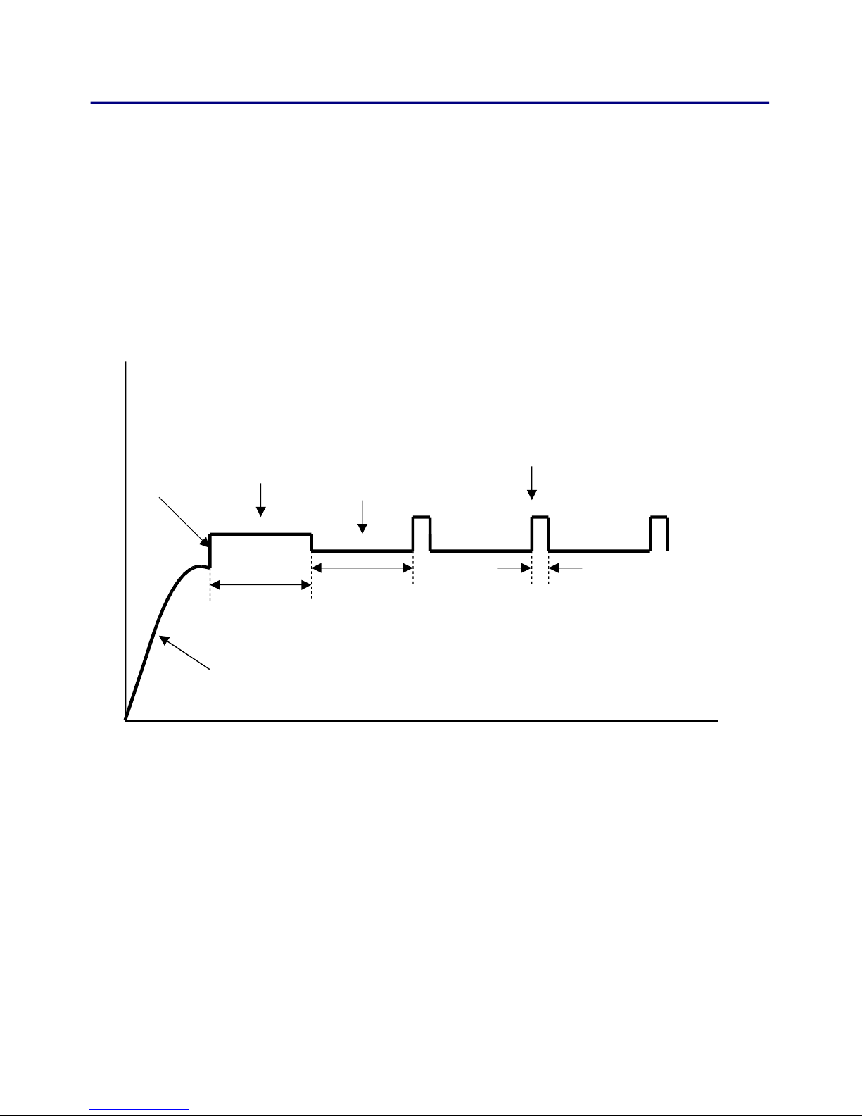
Topreventcorrosiononthe atterypositiveplateduetocontinuousfloatcharging
current(VFloat=13.65V),theunitutilisesastoragemodevoltage(VStore=
13.25V)whennoactivityonthe atteryisdetected.Thisextendsthe atterylife.
Duringstoremode,theunitexitsto oostmode(VBoost=14.05V)for15minutes
every24hrstomaintainchargeinthe attery.If atteryactivityisdetectedduring
storemodeitexitsautomaticallyintofloatmode.
14
Figure2:BatteryChargingoverTime
24Hrs
15Mins
Periodic VBoost
(14.05V)
VStore
(13.25V)
VFloat
(13.65V)
24Hrs
Trickle Charge
(0.8Amps)
LVD Close
(11.5V)
Time

FrequentlyAskedQuestions
STIIICanGelbatteriesbeusedwiththeSTIII?
Yes.HoweverPLCAarenotrecommended.Pleasecheckrecommended attery
specificationsfromyourdealer.
STIIICanyouuseadeepcyclebatteryontheSTIII?
Yesyoucan,howevertheST35IIIisa etteroptionforthechargingcapa ilities
andwillhavealongerlifespan.
STIIIIstheSTIIIaSmartcharger?
TheSTIIIisasimple"Float"charger,theoutput( attery)voltageissetto13.65V
andcurrentlimitedto10A.TheSTIIIisa"4stagesmartcharger".
STIIICanIaddagenerator?
ThetypeofgeneratorusedwillimpactonhowtheSTIIIworks.Testshaveshown
thatgeneratorsthatprovideasquarewaveoutputhavealowerpeakvoltageand
maynotprovidethevoltagerequiredtoruntheSTIII.
STIIIWhentheAuxIN+terminalisusedfromthetowcar,isthisa
"straight"throughconnectiontothebattery?
TheAUXinprovidesanothersourcetooperatetheoutputloadsandchargethe
attery.IthasadiodetoensureonlycurrentcanentertheSTproductthrough
theAUXin.
STIIIHummingnoisewhenradioison.Isometimegetahummingnoise
whenlisteningtoAMradio.Whatisitandcananythingbedone?
TheSTIIIdoesoccasionallycauseinterference(orhumming)ontheAM andin
someinstallations.TheinterferenceoccurswhenthereisnoloadontheSTIII
duetopulseskipping,e.g.the atterynotconnectedwhenpluggedinto240V
mains.OnesuggestedwaytoreducethepulseskippingistolightlyloadtheSTIII
yturningonalight.PhysicallymovingtheradioortheSTIII(moredifficult)can
sometimeshelpreduceorstopthenoise.
15

TrailerPlugOperation
TowiretheSTIIItothecarfollowthediagramsforthedifferentplugtypes.For
moreinformationpleasecontactyourdealer.
16

AftersalesService
WARNING:Donotdisassemble,modify,orrepairtheunit.
Doingsomayresultinelectricshocksorfire.
RepairsandAftersalesService
ConsultyourSetecdealer.
17

WarrantyTermsandConditions
The enefitsprovidedtoyouunderthiswarrantyareinadditiontoanyotherrights
orremediesyoumayhave,asaconsumer,underanyotherlawwhichappliesto
SetecPtyLtdproducts.SetecPtyLtdgoodscomewithguarantiesthatcannot e
excludedundertheAustralianConsumerLaw.Youareentitledtoareplacement
orrefundformajorfailureandforcompensationforanyreasona lyforeseea le
lossordamage.Youareentitledtohavethegoodsrepairedorreplacedifthe
goodsfailto eofaccepta lequalityandthefailuredoesnotamounttoamajor
failure.
UnderthiswarrantySetecPtyLtdagreestorepairorreplace,atourcost,the
productpurchased yyouinAustraliaiftheproductdoesnotperformin
accordancewiththemanufacturer'sspecificationsduringtheperiodofthis
warranty.
TheSTIIIwarrantyisvalidforaperiodofoneyearfromtheoriginaldateof
purchase.Pleaseretainyourproofofpurchase,asthiswillneedto eprovided
shouldyouwishtoclaimunderthiswarranty.
To ea letoclaimunderthiswarrantyyoumust
(a)Ensuretheproductisinstalled yasuita lyqualifiedpersonandisinstalledin
accordancewiththisOwner'sManualandanyapplica leAustralianStandard.
( )Theproductmust eoperatedinaccordancewiththeinstructionsdetailedin
thismanual.
(c)Theproductmust emaintainedinaccordancewiththeinstructionsdetailedin
thismanual.
Whatisexcludedfromthiswarranty?Coverforanydamage,malfunctionor
failureresultingfromincorrectinstallation,accidentaldamage,misuse,a use,
tampering,unauthorisedrepairs,unauthorisedmodification yanyperson,
corrosiveenvironment,orinfestation yinsectsorverminareexcludedunderthis
warrantyandSetecPtyLtdacceptnolia ilityforthesame.
Howtomakeaclaimunderthiswarranty.
(a)ContactSetecPtyLtdon0392138400,oryourSetecdealer,too tainreturn
authorisation.
( )Packagetheproductadequatelytopreventanyfurtherdamage,andsendthe
producttolocationprovidedwhenyoureceivedyourreturnauthorisation.
(c)Pleaseincludewiththeproduct,proofofpurchase,adetaileddescriptionof
thefault,andyourcontactdetails.
SetecPtyLtdmayseekreim ursementofanycostsincurred ythemifaproduct
isfoundto eingoodworkingorder.
18

000000Rev5A
DESIGNEDAND
MANUFACTUREDIN
AUSTRALIA
Table of contents
Other Setec Power Supply manuals


