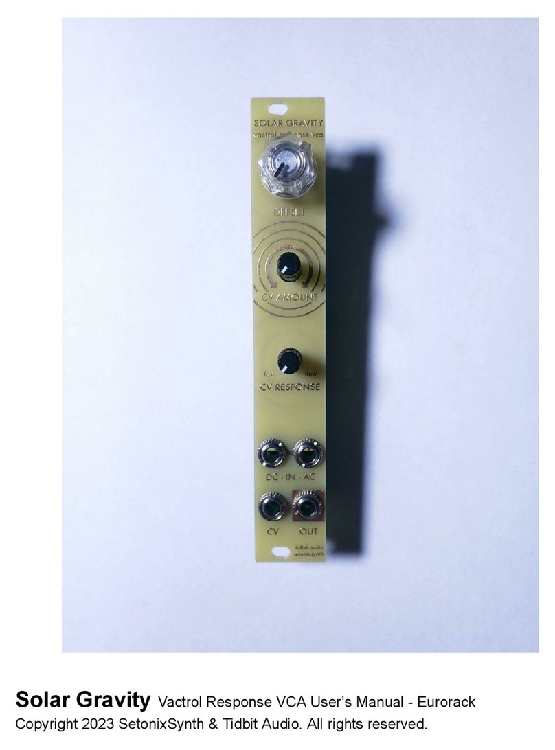
7. Once all other hardware is secured, solder the two plastic potentiometers using the following method:
-Solder one leg of one pot
-Check to see if the pot is mounted in such a way that it does not touch the panel when turned
-If it isn’t, use a finger to adjust the pot’s position while heating the one soldered pad
-Once the pot is not touching the panel, solder the second leg, double check and solder the pins
-Repeat for other potentiometer
Step 7 & 8: Fully soldered Solar Gravity.
8. Double check your work. Make sure that all hardware is properly soldered to the PCB, and that nothing
on the board has been damaged while soldering. If everything looks good…
8. Plug in your Solar Voltages. Patch audio into first the DC input then the AC input and listen to the
module’s Output. Even uncalibrated, turning the Offset knob should change the volume of the signal
going through, and the output should sound like the input with no distortion though the volume will
probably be different. You can also patch CV such as an LFO into the CV input and adjust the CV Amount
and CV Repsonse potentiometers to test that they are functioning.
9. Calibrate your Solar Voltages. (For best results, use an oscilloscope!)
a. With nothing patched to the CV input, turn the Offset potentiometer all the way CCW. The frontal
LEDs should abruptly turn off only slightly before the knob reaches full CCW. If they do not, adjust
the LED OFFSET potentiometer until the LED turns off right at full CCW, then turn the trimmer
another half turn or so.
b. Patch a VCO at audio rate to either the DC or AC input of the module. If you have an
oscilloscope, use it to monitor the waveform coming from the Output. Turn the Offset
potentiometer fully CW and adjust the OUT-GAIN potentiometer so that the Output is the same
level as the Input.
